14 | Transformers
On one level the transformer is a very straightforward device, and yet transformers can also represent a complex topic requiring much know how and a significant amount of analysis in order to specify and deploy them effectively. Fortunately this degree of detail is not required for the kind and level of application considered here. In simplest terms a transformer consists of nothing more than two coils of wire (referred to as windings) mounted close together but not electrically connected. A signal in one winding induces a corresponding signal into the second. To aid this signal transfer the coils of wire are wound around a core made from iron, ferrite, or similar ferromagnetic material. While many other details are needed to fully characterise a typical transformer, this is as much of a description as is required here. Figure 14.1 illustrates the basic structure of a transformer.
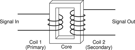
Figure 14.1 The basic structure of a transformer, consisting of two windings wrapped around a common core.
The most familiar description of the function of a transformer is that it changes the voltage level of a signal either up or down, but this is not the only thing that transformers do, and often it is more of a side effect of their intended function in a circuit, and not their primary role. In addition to voltage and current transformation transformers can also provide electrical isolation, signal balancing, polarity inversion, and impedance adjustment. All these aspects of a transformer’s operation are examined in the sections which follow.
Transformers come in a wide variety of shapes and sizes. Figure 14.2 illustrates two of the commonest forms of transformer which are encountered in audio electronics. Transformers are also seen in numerous variations of these formats but the ones shown here are typical. Size, shape, weight, and electrical connections can all vary widely depending on the particular device involved and the application for which it is intended.

Figure 14.2 Examples of the two basic transformer form factors.
Given that two coils is about all that a transformer consists of, it should come as no great surprise that the key characteristic which allows its performance to be analysed is the relationship between these two windings. Specifically what is of interest is the number of turns of wire in each winding. As such, the most fundamental metric defining the action of a transformer is its turns ratio, which is defined as the number of turns of wire on the secondary winding divided by the number of turns on the primary. This relationship is expressed mathematically as Eq. 14.1 in the Transformation Equations section (p. 244), where transformer behaviour is presented in a more formal context.
How Transformers Work
Chapter 2 introduced the idea of electromagnetic induction in the section on electricity and magnetism. There the process is described in terms of a conductor moving through a magnetic field in order to generate electricity. Transformers operate on the same basic principle, except that here the conductor remains stationary while the field itself moves (by growing and diminishing as the signal in the primary winding varies).
When current flows in a conductor, an electric field forms around that conductor. If the current changes so does the field. An alternating current (like a sine wave or an audio signal) is constantly changing and hence generates an ever varying field. If a second conductor is placed close to the one carrying the signal, the electric field being generated by the first surrounds the second, and can thus induce a current to flow in this second conductor. This describes the fundamental action which underlies the operation of a transformer. A signal in one wire induces a signal into another close by.
To achieve better signal transfer the two coils are wrapped around a core which helps to transfer the energy from the first coil into the second. The core can take a number of forms but generally transformers will come in one of two basic formats which might broadly be designated E-I and toroidal (see Figure 14.3), based on the physical shape and structure of the core. The core material will often be laminated, that is to say instead of being a solid piece of material it is built up of layers each one insulated from its neighbours. This helps improve the efficiency of operation of the transformer. Alternatively the core may be moulded from a ferrite material (basically a form of metallic dust in an insulating paste). This serves the same function as the laminations, again optimising the efficiency of the device by minimising the amount of energy lost in transit.

Figure 14.3 Transformer cores: (a) illustrates a laminated E-I core removed from its transformer windings and separated into its collection of E and I shaped parts. (b) shows two toroidal cores moulded from ferrite material.
The two coils or windings of a transformer are designated the primary and the secondary. The incoming signal is sent through the primary coil, and the resulting signal emerges from the secondary. In general, transformers can be used in either direction but will usually be optimised for operation in a particular orientation. In other words either of the two windings might be used as the primary, with the other acting as the secondary. The action of a transformer (in terms of stepping a voltage either up or down) is reversed if the primary and secondary are swapped. One of the most challenging aspects of transformer design and manufacture addresses how these windings are configured. While for some applications it is enough to simply wind one coil and then the other on top of it, often a more elaborate approach is needed in order to achieve the performance required. Bi-filar winding for example involves spinning the two coils simultaneously so that the turns of each are interwoven. When wound in parts, the primary and secondary may be shielded from each other to avoid unwanted interactions. These and other details explain the wide range of types and varying qualities of transformers which may be encountered.
The practicalities of designing and building a high quality transformer are much more complex than the details which are examined here. Without such attention to detail a transformer will quickly start to introduce distortion and bandwidth limitations and variations, and to pick up noise and interference. In pro-audio circuit design the selection of the best transformer for a particular job can involve a lengthy and detailed analysis. High end transformers can be very expensive. Lo-fi audio transformers suitable for experimentation and use in DIY projects can on the other hand be bought quite cheaply from the major online electronics component distributors.
Transformation Equations
Turns Ratio
One of the commonest ways to characterise a transformer is as either step up or step down. In a step up transformer the voltage level of the signal emerging from the secondary winding is larger than the original signal level which is presented at the primary. By contrast, in a step down device the output level is lower than the input level.
As previously mentioned, the characteristic of a transformer which defines how it will manage this task of either stepping up or stepping down the incoming signal voltage level is called the turns ratio. A transformer’s turns ratio (k) is calculated as the number of turns of wire on the secondary winding divided by the number of turns on the primary, as shown in Eq. 14.1 where Nsec is the number of turns on the secondary and Npri is the number of turns on the primary. Notice that if there are fewer turns on the secondary than on the primary then k is a number less than one. This identifies the transformer as a step down transformer. Conversely if Nsec is larger than Npri then k is greater than one and it is a step up transformer. An equal number of turns on the primary and secondary means k = 1 and the transformer is what is sometimes referred to as an isolation transformer, which passes a signal unchanged in level.
It is worth noting that there is a commonly encountered alternative format in which the turns ratio can also be written. In mathematics a ratio is often expressed as two numbers separated by a colon, so another way of presenting a transformer’s turns ratio would be Npri : Nsec. However, consider a transformer with 1,000 turns on its primary winding and 200 on its secondary. By Eq. 14.1 k = Nsec/Npri = 200/1000 = 0.2. This could
also be written using the ratio notation as 1000:200, but in fact it will almost always be simplified down to use smaller numbers in the appropriate ratio, in this case 5:1. Note that in the ratio notation Npri comes first but in the calculation of Eq. 14.1 it is Nsec which comes first.
Power Transfer
The idea that an electronic component without a power source can make a small signal into a bigger signal (say turning 9V into 1000V) may at first seem a bit too much like getting something for nothing. This is of course not the case. It is important to remember that what transformers really do is trade voltage against current, they can step up or step down the incoming voltage, or leave it unaltered, but if the voltage goes up the current must go down by the same factor, and vice versa. Ultimately the amount of power coming out of the secondary equals the amount of power going into the primary (minus some small losses incurred in the process), as expressed by the rather trivial expression in Eq. 14.2. The efficiency of a transformer indicates how great these losses will be. A good transformer used in a correctly designed circuit will typically exhibit a very high efficiency, usually well above 90%. This means that only a small fraction of the power coming into a transformer will be lost as heat. Most will be passed on to whatever circuit is connected to the secondary.
Voltage Transformation
While power remains approximately constant, the other attributes of an incoming signal will usually be altered when it emerges. The turns ratio is key to understanding how a given device will affect any signal. This quantity can be used to see what effect a transformer will have on the signal voltage and current transferred from the primary to the secondary. It also tells how impedances will be mirrored through the transformer. Input and output impedances are important quantities in audio systems. It is often necessary to ensure that the appropriate impedances appear at various points in a system in order for it to operate efficiently, with minimum distortion and maximum signal transfer. Eqs. 14.3–14.5 specify how the transformer turns ratio defines the action of any given transformer. Eq. 14.3 states that the voltage which will appear on the secondary will be k times the voltage which is placed on the primary.
Current Transformation
As stated above increasing voltage means decreasing current and vice versa. As such it is entirely predictable that the form of Eq. 14.4 for current transformation entails division rather than multiplication by k. And so it is that the current on the secondary winding is the current on the primary divided by the turns ratio.
Impedance Transformation
The interpretation of Eq. 14.5 can at first be a little difficult to grasp. Put into words this equation might be expressed as, the apparent impedance when looking into the secondary is k squared times the actual impedance attached to the primary. This is a very important concept in audio electronics because input and output impedances play a key role in successful audio electronic circuit design.
Schematic Symbols
The three most commonly encountered versions of the circuit symbol used to indicate a transformer in a schematic diagram are given in Figure 14.4. There is no difference between the meaning of these three symbol styles and they are entirely interchangeable. The close relationship between inductors and transformers can be seen in the fact that inductor circuit diagram symbols also come in the same three common variants, as illustrated in the symbol table in Appendix C.

Figure 14.4 Three common variants on the transformer circuit diagram symbol.
Many variations on these basic forms may be seen; Figure 14.5 illustrates a number of possible variants, each one indicating some additional information about the device being represented. The meaning and significance of all these different symbols are explained below. Transformers can have different numbers of input and output connections. Both input and output can consist of one or more coils or windings, and each winding, as well as its end points may have one or more taps (midpoint connections) at various positions along its length. Transformers can also be made with a few different types of core structure and material, and may or may not also include a screen or shield connection which can be used to minimise noise pickup by the device. They might also be enclosed in a metal can to further shield them from their surroundings. Almost all these options and alternatives can be indicated directly on the circuit symbol and as such there are lots of variations on the basic symbols shown here which may be encountered.
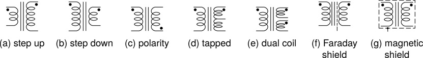
Figure 14.5 Transformer symbols may include additional information.
The symbols in Figure 14.5 have the following interpretations:
Step up – with more turns indicated on the secondary winding than on the primary, the turns ratio (k) is greater than one, and thus the output voltage level is greater than the input. This is referred to as a step up transformer.
Step down – this time the primary has more turns, indicating a k less than one, and a reduction in voltage on the output relative to the input. This is referred to as a step down transformer.
Polarity – the dot inserted beside one of the connection points on every winding indicates which connection represents the start of the winding. A signal passing through a transformer can always be extracted with its polarity either unaltered or reversed. Attention to the position of the dot ensures the desired polarity is maintained.
Tapped – one or more taps may be present on either or both windings. These provide alternative connection points to accommodate different input or output signal levels. A tap at the midpoint of a winding is called a centre tap and is often labelled CT. Taps can however be placed anywhere along the length of a winding.
Dual coil – either the primary or secondary side (or both) may consist of more than just a single winding. Multiple coils may be wired in different ways to provide different turns ratios, as well as increased signal handling capabilities. Wiring two coils in series yields a winding with an increased number of turns, while parallel wiring can increase the maximum signal level which can be handled.
Faraday shield – a connection point to a line between the windings indicates the presence of a Faraday shield or electrostatic shield. Grounding this point can minimise the effect of inter-winding capacitance, which can be important in some applications.
Magnetic shield – this takes the form of what is usually called a mu-metal can. This is a special metal can which a transformer is placed inside in order to prevent external magnetic fields from inducing hum or other interference into the signals passing through a transformer.
Transformer Types and Applications
The basic principles underlying the operation of a transformer are extremely straightforward (a signal in one coil induces a signal in another, with relative properties governed by the turns ratio k). However real world transformers involve a range of compromises and competing priorities which leads to a wide array of different transformers designed for different applications. A detailed treatment of how to design or select the best device for a particular application involves considerable technical analysis and is beyond the scope of this book. A good introduction to the topic can be found in Whitlock (2008).
When designing high end audio equipment the transformers deployed can represent a significant proportion of the overall system cost. At the other end of the spectrum however, small inexpensive devices, often generically referred to as audio matching transformers or coupling transformers can be acquired at very modest expense. These devices will not deliver pristine audiophile sound, but they are ideal for experimentation and learning. The example transformer circuits throughout this chapter and elsewhere (with the exception of the PSU circuit) can be built utilising just such transformers, and more details of suitable devices and where to get them are provided below.
Table 14.1 includes details on a small range of transformers from various manufacturers. The devices from Xicon probably represent the best options for general experimentation. They are relatively inexpensive, and the soft metal legs allow them to be inserted easily into a breadboard, making them ideal for building and testing various circuits with the minimum of effort. The Monacor and the first Jensen are transformers specifically designed to be used in DI boxes. While the offerings from Xicon do not fit the bill too closely, something like the 42TL013 or 42TL019 would be perfectly adequate to build a circuit for educational purposes. The topic of transformers and DI boxes is examined later. Looking further ahead to Chapter 16, the 42TL016 would be a prime candidate for the ring modulator circuit described there.
Manufacturer |
Part number |
Impedance |
Turns |
Price guide |
||
pri. |
sec. |
|||||
Jensen |
JT-11-DMCF |
680 |
80 |
1:1 |
1 |
High |
Jensen |
JT-DB-E |
141k |
150 |
11.52:1 |
0.087 |
⇓ |
Monacor |
DIB-110 |
47k |
600 |
10:1 |
0.1 |
|
OEP |
A262A2E |
150 |
600 |
1+1:2+2a |
1, 2, 4b |
|
Xicon |
42TL013 |
1k |
8 |
12.6:1 |
0.08 |
|
Xicon |
42TL016 |
600 |
600 |
1:1 |
1 |
|
Xicon |
42TL019 |
10k |
600 |
5.128:1 |
0.195 |
Low |
a. Indicates dual windings on both primary and secondary sides.
b. Different turns ratios are possible depending on how the dual windings are wired.
The three Xicon devices all come in the same format, with centre taps on both primary and secondary. The OEP has dual windings on both sides, hence the odd specification of the turns ratio. By wiring these windings in various combinations of series and parallel, k values of 1, 2, and 4 can be achieved. The OEP also sports an electrostatic shield. The Monacor is centre tapped on its secondary, as illustrated in the schematic in Figure 14.7. In the case of the Jensen devices, the JT-11-DMCF provides the bare essentials with just a primary and a secondary winding, while the JT-DB-E is a more elaborate affair with a total of seven connections. Four provide access to the primary and secondary as usual, while the final three connect to dual Faraday shields (one for each winding) and a magnetic shielding can. These examples are by no means exhaustive of the types and applications encountered. They are a snapshot of a range of potentially useful devices.
More broadly in audio electronics transformers are encountered in two main contexts. Power transformers take mains voltage and transform it to the various voltage levels needed in any given system. As many different output voltages as are needed can be tapped off the secondary side of the transformer. Power transformer are designed for the amount of power they can transfer (unsurprisingly), and good designs also aim to minimise and contain the potentially large magnetic fields which they can generate. Such fields can represent a major source of interference if care is not taken to contain their effects. On the other hand power transformers (unlike audio or other signal transformers) care little about the faithful reproduction of the signal shape as it is passed through the device. Linearity is not such a concern here.
The second class of transformer encountered in the area of audio electronics along with power transformers are of course audio transformers themselves, which are the primary focus here. These can be further subdivided into a number of different categories depending on their characteristics and intended function. Such categories include output transformers, input transformers, matching transformers, and coupling transformers. Audio transformers are used in the interfacing of audio circuits, and as such, unlike power transformers, they aim to pass signals as undistorted and as noise free as possible.
In DIY audio circuits a transformer will occasionally be found employed as an inductor, where the second winding is usually left unconnected. On the whole transformer windings make for rather poor inductors, but experimentation can yield some interesting results nonetheless.
In considering the particular tasks which a transformer might perform in a circuit, there are a number of key elements to be addressed. The functions which a transformer may serve include voltage and current transformation, polarity Inversion, electrical (aka galvanic) isolation, signal balancing, and impedance adjustment.
Voltage and current transformation are the functions already addressed most explicitly in the chapter so far. The transformer in a power supply for example takes mains voltage and converts it to a different (typically much lower) level as the first step in generating a DC power output signal. The full AC to DC power supply process, entailing transformation, rectification, and smoothing is considered in Chapter 16 on didoes (with the final optional regulation step addressed in Chapter 18). Similarly, a transformer may be used to drive an audio transducer. As mentioned previously, transformers can trade voltage and current. A circuit suited to driving a moving coil loudspeaker is unlikely to be able to successfully drive a piezo sounder (the piezo needs more voltage than the speaker, but not nearly as much current). Inserting an appropriate transformer can take a signal suitable for a speaker and convert it into something better able to drive the piezo.
Polarity inversion comes for free with a transformer. Simply reversing the connections to either the primary or secondary winding of the transformer will provide an inverted signal to the following circuitry. However, transformers are big and they are expensive, so it is unlikely that one would be included in a circuit solely for this purpose. If one is to be utilised for other purposes, it does provide a simple means to providing this functionality in addition.
Electrical (galvanic) isolation refers to a situation where there is no direct electrical connection between two points in a circuit. As the two sides of a transformer are not directly connected, transformers provide just such an isolation between their primary and secondary sides. This can be desirable on two grounds, firstly as a safety feature limiting the potential for electric shock, and secondly it can provide a means for eliminating noise from a system by interrupting unwanted ground loops.
Signal balancing describes a method for transferring signals which has the potential to avoid picking up noise during transmission. Transformers provide a very straightforward method for converting an unbalanced signal into a balanced one. This is a good thing to do before sending a signal over any distance, especially in a noisy environment.
Impedance adjustment is another function which, like voltage and current transformation, has been addressed already in the main discussion above. The effect is described in Eq. 14.5, and represents a major aspect of the way in which transformers are used to improve the interfacing of signals across circuit with different output and input characteristics.
Transformers and DI Boxes
Many if not most DI boxes (both passive and active) incorporate a transformer. Many passive DI boxes contain little else. Transformers provide for most of the important tasks which the typical DI box is designed to accomplish. In particular signal balancing, impedance adjustment, and galvanic isolation are key aspects of what a DI box is designed to be used for. Figure 14.6 shows a very simple passive DI circuit which accomplishes all three tasks, with a TS jack input, an XLR output, a ground lift switch, and at its heart a 10:1 step down transformer. Passive DIs typically employ a transformer with a turns ratio in the vicinity of 10:1 to 14:1.
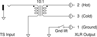
Figure 14.6 Circuit for a very simple passive DI box using a transformer with a 10:1 turns ratio (k = 1/10 = 0.1).
Typically a relatively short unbalanced TS lead from a guitar, synthesiser, laptop computer, or other unbalanced sound source is plugged into the input of a DI box, and a potentially much longer balanced XLR cable connects to the DI’s output and takes the signal on to its destination. As alluded to above, a number of benefits can accrue from using such an arrangement rather than simply making the connection with a long TS to XLR cable.
Using just a cable means the full length of the connection is unbalanced. The main benefit of a balanced connection is its ability to reject noise which is picked up along the length of the cable. The balanced output of the DI can form one end of a balanced connection and thus reap the benefits in reduced noise and interference.
The importance of appropriate output and input impedances at either end of an interface has been highlighted previously. In most cases an impedance bridging arrangement is desirable. This is when the input impedance is significantly higher than the corresponding output impedance. Usually a factor of about ten is cited as appropriate. (Impedance matching, where the output and input impedances are equal, is also common in some situations, especially for digital or other high frequency connections. For the kind of analog, audio frequency connections considered here, bridging is preferred.)
When a relatively high output impedance source (like an electric guitar) is to be connected to a standard audio input, it is usually beneficial to insert a DI box to achieve a more appropriate ratio of output to input impedances. The 10:1 transformer in the example above corresponds to a turns ratio of k = 1/10. From Eq. 14.5 it can be seen that the resulting transformation factor is k2 = 1/100. This means that the high output impedance of the electric guitar, when viewed from the output of the DI box will be divided by a factor of 100, bring it down to a level much more suitable for interfacing with a typical microphone or line level input.
The third benefit attributed to the transformer was galvanic isolation. Sometimes this is desirable, and sometimes it is not. The ground lift switch allows or defeats this isolation depending on its position. When the switch is closed, the ground connections on the primary and secondary sides are joined and isolation is defeated. This most likely to be the desired situation for something like an electric guitar. Linking the grounds holds the ground potentials on either side together, and thus maximises signal headroom.
However if the equipment on both sides of the DI box has a connection to mains earth ground (e.g. a synthesiser connecting to a sound desk, both mains powered), then the connection through the closed ground lift switch completes a ground loop, and ground loop noise is likely to ensue as a result. Opening the switch breaks the loop and prevents the noise currents from flowing.
Figure 14.7 provides the schematic diagram for a fully fledged passive DI box including parallel output, 0dB/−20dB/−40dB switchable pad, and ground lift switch. It is a worthwhile exercise to confirm that the resistors shown in the pad circuit do indeed provide the specified levels of attenuation. The pad setting is selected using a dp3t switch (see Chapter 15). In position one (as shown in the schematic) the two halves of the switch combine to bypass the resistors completely. This is the 0dB, unpadded setting.

Figure 14.7 Full circuit diagram for the DIB-100 DI box from img Stageline. This DI box uses the Monacor DIB-110 10:1 transformer – they are in fact the same company.
In position two R1 = 47k and R2 = 5k6 come into play, forming a voltage divider between the input and the connection feeding the transformer. The voltage divider rule can be used to see what fraction of the signal makes it into the transformer, and then the decibel equation can be used to turn that fraction into an attenuation in decibels.
Voltage divider rule |
|
Rearrange |
|
Decibel equation |
|
Substitute |
|
Insert values |
|
= −19.5dB |
Calculate |
With an aim point of −20dB for the first pad, this looks perfect. Anything less than a decibel out is considered to be negligible. Exactly the same calculation can be used for the second pad position. In this final position the switch selects R1 and R3, so the 5k6 is replaced with 470. This leads to a pad level of −40.1dB as shown below, again well within the required range.
| Insert values | |
| = −40.1dB | Calculate |
Transformers as Output Drivers
A typical small signal transistor does not have the current handling capability to drive a loudspeaker directly. Feeding its output through a suitable transformer can significantly improve this situation. It won’t go very loud, and it won’t be very clean, but it can prove an interesting effect. The extravagantly titled ‘Ultra Class A Superdrive Power Amp’ from Escobedo’s ‘Circuit Snippets’ collection provides a very simple circuit in this mode. If the suggested Radio Shack transformer can not be found, it could reasonably be replaced with a Xicon 42TL013 or something similar. Notice that the secondary impedance of this transformer is listed in Table 14.1 as being 8Ω. This is something of a giveaway that this transformer is most likely specifically intended for interfacing directly to an eight ohm loudspeaker.
In the example above, the device is used in its intended orientation, as a step down transformer, trading voltage for current, to better drive the low impedance load of the loudspeaker. Another common kind of audio transducer besides the loudspeaker is the piezo driver. However, a piezo element presents a very high impedance and, as such, an amplifier designed to drive a standard loudspeaker is unlikely to be able to get much life out of a piezo. What is needed is more voltage, and since the high impedance piezo also needs very little current, the transforming properties of a transformer should be able to convert an output suited to driving a loudspeaker into one more able to handle a piezo.
Figure 14.8 illustrates this situation – Figure 14.8a shows a 386 audio power amplifier connected directly to a loudspeaker as it is intended to be used. In this configuration the circuit will operate as expected and sound will emerge from the loudspeaker in the normal fashion. In Figure 14.8b however the loudspeaker has been replaced with a piezo driver. There is nothing wrong with the circuit per se, but the piezo will produce a very weak signal if any at all. There simply isn’t enough voltage available to get the piezo to move very much.
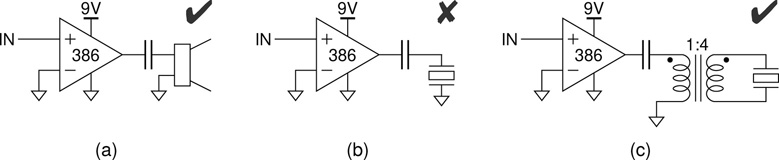
Figure 14.8 Using a step up transformer in order to trade current for voltage so as to better drive a piezo sounder from an amplifier output designed to drive a much lower impedance load. (a) The 386 as it was intended to be used. (b) Trying and failing to drive a high impedance load. (c) Using a transformer to better match source to load.
A step up transformer placed between the amplifier and the piezo driver will increase the voltage available, and get the piezo moving sufficiently to generate some sound. The transformers described so far are mostly designed as step down devices, but by reversing their connections between primary and secondary they can be used in the opposite direction in order to step a signal up. Therefore, the configuration shown in Figure 14.8c can be implemented using, for example, a 42TL013 or 42TL019 transformer with primary and secondary connections swapped.
References
G. Sowter. Soft magnetic materials for audio transformers: History, production, and applications. Journal of the Audio Engineering Society, 35(10):760–777, 1987.
B. Whitlock. AN-002: Answers to Common Questions About Audio Transformers. Jensen Transformers, 1995.
B. Whitlock. Audio transformer basics. In G. Ballou, editor, Handbook for Sound Engineers, ch. 11, pp. 273–307. Focal Press, 4th edition, 2008.