15 | Switches
The humble switch seems a trivially simple topic at first glance but there is much more to this versatile component than might be immediately apparent. In its most basic form it is indeed a very straightforward device; the function of a light switch or a doorbell buzzer is no more than to make and break a single electrical connection. This is achieved using what would be called a single pole single throw or spst switch. Poles and throws are two key concepts for switches, and a switch might have (in theory) any number of each – more on this later.
Figure 15.1 illustrates the three basic roles which a switch can play in the operation of an electrical circuit, as given in the one line description at the top of the chapter. Before getting into the details of these and other operational aspects of switches, an overview of common switch styles is presented. The term ‘style’ is used here to refer to the mechanical design as opposed to the electrical characteristics of a switch.

Figure 15.1 The three basic functions which a switch can perform are illustrated here. Consider signals flowing from left to right in the three examples above. In routing, the incoming signal can be routed to either one of two different destinations. In connecting, the incoming signal can be switched in or out of the circuit. In selecting, just one of the two incoming signals is selected to continue on.
Unlike most electronic components, the switch is also a prime candidate for homemade variants, from tilt switches to finger contacts and much more beside. Collins (2009) includes some interesting suggestions for experiments in this area.
Switch Styles
Switches come in many shapes and sizes, such that the same electrical functionality may be achieved using a wide variety of physically different devices. The brief catalogue which is presented in Table 15.1 is by no means exhaustive. It does however cover most of the major categories which are commonly encountered in audio technology and DIY audio electronics building, and one or two other less common types besides. Most of the switch styles illustrated here will encompass several variations and subtypes. These vary dramatically in physical size. Some include locking devices to prevent accidental operation. Others may have indicator lights to show their current state. They might have legends, adjustable actions, or other special features. All these options and more might need to be considered when selecting what switch to use in a given application.
Example |
Notes |
|
Toggle |
|
Toggle switches are probably the most common switch type used in DIY audio electronics projects. |
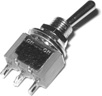
Rocker |
|
Rocker switches are very commonly used for ON-OFF type applications. They often include a status light within the rocker. |
Slide |
|
The mechanism in slide switches is often cheaper and hence less robust than other switch styles. |
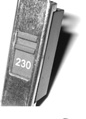
Push |
|
Push switches can be very compact. They are commonly found in keypads and keyboards. They can be momentary or latching types. |
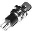
Pull |
|
Pull switches are usually latching but can also be momentary in operation. Almost always single or dual throw. |
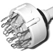
Rotary |
|
Rotary switches are particularly good when a large number of switch positions are needed. The illustration shows an ‘sp12t’ type – a single pole, and twelve throws. |
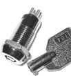
Key |
|
The power on high end gear might be controlled using a key switch. Special programmer or configuration modes may also be accessed this way. |
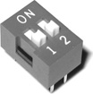
DIP |
|
DIP switches are used to set seldom changed options. DIP stands for dual inline package, and refers to the layout of legs in two rows. |
Reed |
|
Reed switches are actuated by a magnet. Good for detecting when two objects come close to each other, or when they move apart. |


Switches are one of the main hardware interface components encountered, along with such things as pots and faders, connectors, indicator lights, and meters. As such not only their electrical characteristics but also their mechanical action and physical design are important. For instance the push switch style might be the most appropriate for playing notes on an instrument, while a toggle switch might be better suited to selecting modes of operation (perhaps engaging filters or selecting waveforms in a synth). Similarly, less often accessed functions (perhaps the pad select on a DI box) might be most conveniently accomplished using a slide switch, and critical controls like the main power on a large console might benefit from a key switch to avoid accidental power down.
Determining the electrical characteristics required in a particular application is only the first step in selecting the right switch for the job. Many factors can come into play in the selection of the most appropriate switch style for a particular application including cost, availability, ease of use, aesthetic look and feel, robustness, footprint and profile, in addition to electrical characteristics such as voltage and current ratings. When experimenting or when building one off circuits the deciding factor is often availability – what suitable switch can be most readily found amongst the components currently to hand. So long as it provides the required number of poles and throws, the exact switch style is often less critical.
Poles and Throws
As alluded to above, the number of poles and the number of throws are two key descriptors specifying the functionality of any given switch. An individual switch might control any number of separate things simultaneously. Perhaps it is desired to be able to turn the signal on and off to a pair of loudspeakers with a single switch. This will involve breaking two independent connections at the same time, and so the switch used will need two poles; effectively two totally separate switches are actuated by a single control (be it a toggle, push button, slider, or something else).
This leads on to the related property described in the number of throws. Throws indicate the number of different places one connection can be switched between. Returning to the example above, if instead of merely muting the loudspeakers in question, the goal is perhaps to switch between three different sets of speakers to allow easy comparison of a sound source on a number of different systems. For three sets of speakers a three throw switch will be needed – in this case a dual pole three throw (dp3t) switch, as a stereo signal is being switched between three different pairs of loudspeakers.
When naming the type of any given switch, for one pole or throw the term used is ‘single’, for two the term is ‘double’ or ‘dual’, and after that numbers are used. So for instance a very common combination would be the 3pdt (three pole dual throw) switch, allowing three separate things to be switched between two different paths each. The foot switch on a guitar effects pedal (e.g. Figure 15.2) is very often of this type; one pole switches the input signal path between bypassed and affected, the second pole switches the output signal similarly, and the third pole activates a status LED to let the user know the current state of the pedal.

Figure 15.2 A dpdt and a 3pdt foot switch. A standard foot switch for something like a guitar effects pedal will usually be implemented using a heavy duty latching push switch, most often of the three pole dual throw (3pdt) variety.
The number of poles in a switch does not commonly exceed about three, but switches with higher numbers of throws are quite common. For instance some audiophile hi-fi volume controls use a dual pole switch with a large number of throws (perhaps 24 or more) instead of the more conventional volume pot. This means that the volume changes in discrete steps rather than in a continuous fashion, which may seem like a backwards step. However it makes it possible to keep the left-right matching much tighter than is typically achievable with a pot, avoiding shifts in the stereo image as the volume is altered.
Naturally a switch pole can be used in either a one-to-many or a many-to-one configuration (routing vs. selecting). In other words either a single incoming signal can be routed to a number of different destinations or a number of different incoming signals can be selected between, sending only one of them on to the next part of the circuit. A multi-pole switch can have different poles working in either fashion. In the guitar effects pedal example above, the first pole is being used one-to-many (routing the incoming signal either into or around the pedal’s circuitry) while the second pole in the same switch is being used many-to-one (selecting the pedal output either from the main or the bypassed signal path).
Though it may be obvious, it is perhaps worthwhile mentioning that when using a single throw switch it can be wired up either way around without affecting the functionality, as all it is doing is making and breaking a single connection; no alternate routing in or out needs to be considered.
One final purely practical aspect to the selection and use of switches is that it is always possible to use a switch with more than the required number of either poles or throws. The unused poles/throws are simply left unconnected. By and large this would be considered wasteful as switches with higher pole or throw counts will usually be more expensive, but sometimes it is more convenient to make do with what components are readily to hand. In particular dual throw switches are often used in place of their single throw counterparts with one of the contacts left unconnected. One unused throw may be conveniently left unconnected as an ‘off’ position, but leaving more than one throw unused is likely to result in a confusing experience for the user, as multiple switch positions do the same thing.
Momentary vs. Latching
A light switch and a doorbell would both most commonly use an spst switch (in both cases the required action is simply to make or break a single connection). There is however an important difference between the actions of these two devices. When a light is switched on it should stay on until switched off again, while with a doorbell it should ring when pressed and stop when released. The former requires a latching action (sometimes called ‘successive operation’ for a push style switch), while with the latter the action is referred to as ‘momentary’ or ‘biased’. A momentary switch only stays switched as long as it is held (like a door bell). A latching switch remains in its current position until it is switched to a new position by the user (like a light switch). The keys on a keyboard are going to be momentary switches while the routing buttons on a console will be latching. In circuit diagrams the labelling ‘MOM’ is sometimes found beside a switch in order to indicate that the specified component is intended to be a switch with a momentary action.
Radio Buttons
The term radio buttons refers to a set of separate but interconnected latching push switches. The idea is that only one of the buttons can be latched into its pushed down setting at any given time. When one of the buttons is pressed, whichever other button was previously latched down automatically pops up. The name comes from this type of buttons most common original use. On old radio sets the user could often select the band using a set of radio buttons. Car radios used to provide a selection of pre-tuned stations in the same way. Similar functionality could be achieved using a rotary switch for instance, although unlike the radio button solution, it would not be possible to move between two non-adjacent settings without passing through the intervening positions.
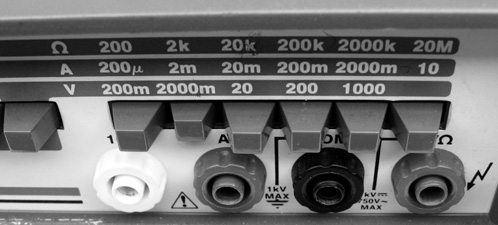
Figure 15.3 Radio buttons used to select between measurement ranges on a benchtop multimeter. Here the second of six is currently selected.
Normally Open (NO) vs. Normally Closed (NC)
A single throw momentary style switch (think door bell buzzer or keyboard key) can act either as an open switch which is closed when pressed, or a closed switch which is opened when pressed. Some fairly self explanatory terms are used to describe switches of these two types. A switch which is closed when pressed and is otherwise open will be referred to as ‘Push-to-Make’ or ‘Normally Open’ (often abbreviated NO). Conversely a switch which is open when pressed and is otherwise closed will be referred to as ‘Push-to-Break’ or ‘Normally Closed’ (often abbreviated NC).
The former action is by far the more common (the doorbell and keyboard examples cited above are both of this type) but the latter exists also and can sometimes be more appropriate for a given application. In particular the dead man’s switch style will usually be a momentary, normally open switch type, the idea being that the switch must be kept actively engaged to maintain a connection. Locomotives, power boats, and some sports vehicles employ dead man’s switches so that the engine will stop automatically if the driver is away from the controls for whatever reason. This might be in the form of a foot switch which must be kept depressed, a cutoff tether clipped onto the drivers clothing, or an under seat switch needing a persons weight to keep it actuated.
Two standard circuit diagram symbols exist for push-to-make and push-to-break style switches, as illustrated in the ‘spst NO’ and ‘spst NC’ entries in Table 15.2. Imagine pushing down on the vertical bar to see what the switch does.
| Circuit diagram symbols for various types of switch | ||||
| spst | spdt | spdt on-off-on | spst NO | spst NC |
| dpst | dpdt | dpdt (alt.) | sp5t | spst relay |
 |
 |
 |
 |
 |
Break-Before-Make vs. Make-Before-Break
Switches involving two or more throws can be manufactured in two slightly different variants called break-before-make (aka BBM or nonshorting) and make-before-break (aka MBB or shorting). As with the terms of the previous section, the names here are fairly self explanatory. In the first instance (break-before-make) when the switch is moved from one position to another the initial connection is disconnected before any connection is made to the next throw contact. By contrast, with a make-before-break switch the new connection is made before the original one is severed. By far the more common of the two is break-before-make, and unless otherwise specified this is the type which should be used. Sometimes it is important to use one type and sometimes the other, and sometimes it does not actually matter too much which is used.
In some circumstances a break-before-make changeover used in an audio circuit may result in a loud click or thump in the audio signal passing through the circuit, which can in some circumstances be much diminished by the use of a make-before-break style switch. On the other hand it will often be the case that make-before-break operation can connect together two things which should never be connected together. Even an extremely brief undesirable connection of this kind can result in serious and permanent circuit damage. As such it is important to insure that the type of switch used is suited to the job at hand. Most often this will be a break-before-make type.
Positions vs. Throws – On/Off Switch Position Designators
Sometimes a switch descriptor will carry additional labelling, with one of the following (or other similar) designators being appended to the name (see for instance the third switch symbol in Table 15.2):
on-(on)
on-off-on
on-off-(on)
(on)-off-(on)
on-on-on
There are a few extra characteristics being shown in these unusual looking codes, indicated by the brackets and the ‘on’ and ‘off’ labels. Each ‘on’ or ‘off’ represents a switch position. Brackets indicate a momentary rather than a latching action and the ‘off’ positions indicate places where there is no electrical connection available. These ‘off’ positions are not counted as ‘throws’ when describing the switch. This explains one way in which (as shall become clear) a switch with three positions might nonetheless be described as only a dual throw switch. With these guidelines in mind the five designators above can be interpreted as follows:
1. A switch labelled on-(on) is straightforward. It is a dual throw switch with one of its two throws being of the momentary persuasion. It normally sits in one position and will only stay in the other position for as long as it is held there. Once released its spring loaded action returns it to its resting position. This might be used to implement some kind of a doorbell circuit, but a doorbell is much more likely to be an spst off-(on) style, as nothing needs to be connected when the buzzer is not pressed.
2. An on-off-on switch is a three position, dual throw switch where the middle position makes no electrical connection (and so is not counted as a throw). All three positions are latching (the moving contact stays there when put there). See Table 15.2 for a circuit diagram representation of this kind of configuration. Off-on-on would also be perfectly possible but this is not a common or standard part.
3. The on-off-(on) style is a simple variation of the previous example where the switch latches when moved off centre in one direction but springs back when moved off centre in the other direction.
4. The (on)-off-(on) variant is another dual throw type following the same pattern as the previous two, but this time both contact positions are momentary, springing back to the central off position when the switch lever is released. This type is sometimes found implementing a kind of a ‘dead man’s switch’ in a motion control system, with forward and reverse available in the two off centre positions, both of which are exited as soon as the switch lever is released.
5. On-on-on could of course be used to describe a totally standard three throw switch, with three latching throws. However using this additional labelling would be redundant. The tags examined here are used to highlight non-standard switch types. It might however seem a suspicious designation to be found describing a dual throw switch. How can a dual throw switch have three ‘on’ positions? In fact dpdt on-on-on and 4pdt on-on-on are both quite common variants. In the dpdt case each movement of the switch only changes the connection of one of the two poles (see Figure 15.4): in position one both poles are at throw one, in position two one pole is at throw one and one throw is at pole two, and in position three both poles are at throw two. The 4pdt variant is effectively just two dpdt on-on-on switches side by side in one package, actuated by a single movement.
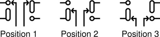
Figure 15.4 The switching action of a dpdt on-on-on switch. In position one both moving contacts connect with the top throw. In position two the left contact only has moved to connect with the bottom throw. In position three both moving contacts have shifted to connect with the bottom throw.
Strangely, quite often when the dpdt on-on-on switch type is encountered it is wired to provide the switching action of an sp3t switch. Actual sp3t switches are relatively uncommon. Figure 15.5 illustrates how a dpdt on-on-on switch is wired so as to act as an sp3t switch. A connection is made from the second throw of the first pole to the moving contact of the second pole. The result is that the moving contact of the first pole is connected successively to: pole one throw one, pole two throw one, and finally pole two throw two. This gives the effect of a simple sp3t switch. Dpdt on-on-on switches are also commonly found in electric guitars, wired for pickup selection. This application is described at the end of the chapter.
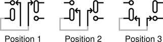
Figure 15.5 A jumper wired as shown linking throw two of pole one to the moving contact of pole two turns a dpdt on-on-on switch into an sp3t switch.
Circuit Symbols
Most of the variations in style and operation described above are not indicated directly on the standard circuit diagram symbols used to show switches. Where particular nonstandard options are preferred or required the circuit diagram or accompanying documentation will include notes to make any particular requirements explicit. Table 15.2 illustrates the most commonly encountered circuit diagram symbols used to indicate switches in a circuit.
As with all circuit diagram symbols, it is common to also encounter variations and non-standard symbols representing switches. The intended meaning of such symbols is usually quite easy to decern but occasionally a little research may be required to confirm a particular interpretation.
A few of the switch variants included in Table 15.2 merit comment, or may need a bit of explanation. The third entry in the table shows an example of a switch with three positions but only two throws. As explained previously, in this on-off-on variant no connection is available when the switch is in its middle position. The ‘NC’ at this position stands for ‘No Connection’, not to be confused withe ‘NC’ for ‘Normally Closed’. The context should always make clear which of these two interpretations of this particular abbreviation is intended.
Following the logic of the designators described in the previous section it can be seen that the fourth and fifth switch types in the table (spst NO and spst NC) could equally well be labelled spst off-(on) and spst on-(off) respectively. The normally open (NO) and normally closed (NC) labelling convention is the standard in this case.
The two dpdt symbols in the table are just two possible alternatives for showing the same dual pole dual throw switch in a circuit. If it is convenient to draw the two switch sections close to one another then the first style might suit, with a dashed line linking the two (or more) switch sections. However if the various sections of a multi-pole switch end up in disparate parts of the circuit diagram it will probably be more convenient to label each one separately, as shown in the second dpdt symbol style illustrated, where SW1a and SW1b indicate two poles of the same physical switch, designated SW1.
Electro-Mechanical and Electronic Switches
Extending the scope of the topic beyond simple mechanical switches, four more involved approaches to switching electrical signals may be considered: electrically actuated mechanical switches (relays), mechanically actuated electronic switches (touch switches), switching transducers (sensor switches), and purely electronic switches. These four categories are examined briefly in the sections which follow.
Relays
A relay is like a normal switch packaged up with a little electromagnet. When a voltage energises the electromagnet it pulls on the switch actuator and moves it from one position to the other. Relays will be either single throw or dual throw styles. The relay circuit symbol in Table 15.2 illustrates an spst off-(on) style. Figure 15.6 shows a 3pdt mains voltage relay capable of switching three independent signals, each of up to 10A, between two separate contacts. Relays may also incorporate various other switch types, such as spdt on-(on) or spst on-(off) variants.
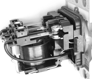
Figure 15.6 A 3pdt mains voltage relay. The large coil visible below forms the electromagnet, while the switching terminals can be seen above.
In each of the three designators presented above, the label for the second position is enclosed in brackets, marking it as being momentary. This is because when the signal energising the relay’s electromagnet is removed the switch will snap back to its original position. Typically relays are actuated using a relatively small signal level energising the electromagnet (via the connections to the rectangle with a line through it in the relay circuit symbol). The signal which is being switched (connected to the switch terminals as shown in the circuit symbol) can be much larger. In the relay illustrated in Figure 15.6 up to ten amps may flow through the switch contacts. This is a very large current and one useful application of a relay is to keep such large currents well away from the control circuitry which switches them. Similar relays are commonly used in car wiring to send a large current from the battery to the starter motor when the key is turned in the ignition. It would be unwise to allow such a large current to flow anywhere near the ignition key (and hence the person turning it). A relay can be used to perform the switching remotely.
Touch Switches
These switches have no moving parts. They can be particularly useful in outdoors applications and in harsh environments, as they are generally robust and can be sealed effectively against water and other contaminants. Resistive touch switches are often used in outdoors locations on elevator buttons, ticket dispensers, and vending machines. Capacitive touch switch technology is the basis of many touch screens on mobile phones, tablets, and computers. Piezo touch switches can be actuated while wearing gloves as they do not require skin contact in order to work. This is in contrast to resistive, and to some extent capacitive styles, which generally do require contact or very close proximity to actuate. Other variations on these basic approaches also exist involving various methods for detecting touch or proximity. The present section is not intended to be in any way a detailed review of this class of switch. The intention is simply to flag the existence and primary features of such switches. These devices tend to be more expensive than traditional mechanical switches and will rarely be encountered in audio electronics applications, although homemade variants can be useful and interesting.
Resistive Touch Switches need two electrodes which need to be brought into physical contact with something electrically conductive (for example a finger) to operate. They work by completing a circuit, providing a path for a small signal current to flow thus allowing an electronic switch to operate. Resistive Touch Switches are much simpler in design and construction than capacitance switches. Placing a finger across the two contact points results in a closed state. Removing the finger turns the switch to its open state. This kind of simple contact switching can be useful in developing unconventional user interface designs. Touching a simple pair of contact points might set an oscillator running or modify a filter for example.
Capacitive Touch Switches need only one electrode to function. The electrode can be placed behind a non-conductive panel like perspex or glass providing great flexibility in the construction and installation of this kind of switch. The switch works using body capacitance – it is able to detect changes in capacitance. When a person touches it, this alters the capacitance and triggers the switch. These devices can also be used as short-range proximity sensors since physical contact is not required in order for the effect to be used. DIY versions are possible and can be interesting to experiment with.
Piezo Touch Switches are based on the mechanical bending of a piezo element (see Chapter 20). This approach enables touch interfaces with any kind of material so long as some degree on movement or vibration can be transmitted through the surface to the piezo sensor behind. Piezo touch switches can be constructed so that a fairly light touch is enough to actuate them even when they are mounted behind stiff materials like stainless steel. Piezo touch switches can also be actuated through contact by any material, unlike the resistive and capacitive styles already described which require direct skin contact or limited other alternatives. Again, piezo transducers are fertile ground for interesting DIY experimentation.
Sensor Switches
Many of the devices in this category are not so much switches in their own right, rather they can be used to detect various kinds of events and provide the actuating signal to an electronic switching circuit. Sensors for all kinds of situations and events are possible.
Light sensors often use simple photoresistors (see Chapter 12) but can also be based on photodiodes, phototransistors, and other light sensitive devices. photoresistors are cheap and extremely easy to use, and as such are found in a lot of simple DIY audio projects. They can be used to control the cutoff frequency of filters or the pitch of audio oscillators amongst many other possibilities. Figure 15.7 shows an optical sensor switch. When an object is placed in the slot, it breaks the light beam passing from one side to the other, and the switch actuates. These devices are commonly found in ticket dispensers and similar machines. Spinning a punched disc of card through the slot could generate an interesting pattern of switching events.
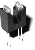
Figure 15.7 A slotted optical switch; when an object is placed in the slot between the LED and the phototransistor, the switch actuates.
Sound sensors are deployed in a wide variety of applications from baby monitors to disco light controllers to clap switches and beyond. Sound sensor boards are available as expansion modules for the arduino and similar microcontrollers. The actual sensor in these is often an electret condenser microphone element, as described in Chapter 20.
Pressure sensors might be considered in two subtypes: mechanical pressure sensors and fluid pressure sensors. The former would include the piezo touch switches described earlier, while the latter would detect the pressure in air, water, or other fluids. Along with piezo elements, pressure sensitive resistive strips can make very versatile tactile interfaces in audio electronics projects. Fluid pressure sensors are of less interest in this area, and are more often found in industrial settings.
Thermostats and temperature sensors are good for monitoring the heat dissipation of circuits and systems but present few obvious opportunities for integration into the kinds of circuits most often of interest here. The thermo-switch shown in Figure 15.8 uses a bimetallic strip to actuate a mechanical switch at a set temperature (this one switches at 80°C).
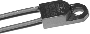
Figure 15.8 A bimetallic temperature sensing switch.
Proximity switches are used to detect when two objects are coming close together. The commonest and simplest type is probably the magnetic reed switch, as illustrated in Figure 15.9. When the magnet is moved close to the glass tube, the fine metal arm within is bent away from its contact point, opening the switch.

Figure 15.9 A reed switch with the bar magnet used to actuate it shown above.
Many other varieties of sensor switching are also possible. The simple mercury tilt switch used to be quite common; a blob of mercury in a glass bulb with two electrodes. When the bulb is tilted so that the mercury touches the electrodes, an electrical contact is made. A homemade tilt switch is an easy thing to make with a metal ball bearing and some nails. More elaborate tilt sensor modules can be used to monitor the motion of machinery, providing information on how much and in what direction it has been tilted. Again, the potential applications in DIY audio projects are probably more limited.
Electronic Switching
There are a number of ways of switching a signal electronically. Computers and other digital devices are at their core primarily extremely large and complex arrays of switches. Probably the commonest and most straightforward way to achieve electronic switching is with the use of transistors. The routing and muting of audio signals in a sound desk is often achieved using simple circuits based on field effect transistors (see Self, 2015, p. 590), as is the bypass switching in many guitar effects pedals. The broad topic of switching electrical signals using transistors is considered more fully in Chapter 17 which introduces and explains the various types of transistor and their typical applications.
Another common approach to electronic switching is using analog switch ICs such as the CD4016BE and CD4066BE. These devices are part of the 4000 series of CMOS ICs discussed in Chapter 18. The CD4051BE and CD4053BE analog multiplexers are other members of the same family, which can also be very useful in simple switching applications. A number of popular arpeggiator and sequencer type noise making circuits uses the 4051 in particular, to great effect. Driven by a simple square wave LFO, it can rapidly switch between a sequence of circuit settings, producing repeating runs of tones.
Instructive Examples
This section details a number of particularly common switching circuits encountered in audio electronics.
Effect Bypass Switching
As mentioned above, various electronic switching methods are often used to implement bypass switching in electric guitar effects pedals. However, many still favour a simple mechanical switching approach. Figure 15.10 shows four possible ways to implement bypass switching using simple mechanical switches. In all cases the basic idea is that a signal source (Src) is connected to a destination (Dst), with the signal either directly connected, or passing through an intermediate circuit (here labelled FX) depending on the switch position. Each scheme represents an improvement on the ones before it.

Figure 15.10 Bypass switching options.
A simple spdt switch routing the source either to the bypass wire or into the FX circuitry might be considered. Unfortunately this leaves the output of FX connected to the destination at all times. Such circuitry can be noisy, especially when its input is left floating, so this is clearly not a great idea.
If an spdt switch is all that is available, then moving it to the destination side provides a better solution. It means that the FX circuit is still being driven by the source – not ideal – but at least its output has been isolated when the switch is in the bypass position.
A much better and much more commonly encountered solution is to use a dpdt switch, so that FX can be isolated both at its input and its output. This a good solution, however the floating FX circuitry can still produce some noise which might find its way into the signal passing close by. In particular, leaving the input of FX floating can result in oscillations and other undesirable mechanisms taking hold.
The forth configuration again uses a dpdt switch, but wires it in a more elaborate fashion. Now when FX is bypassed, its input is also grounded, minimising the chances of undesirable activity in the circuit while it is not in use.
In fact, the foot switch used to implement bypassing on many guitar effects pedals is often actually a 3pdt type, like the one shown in Figure 15.2. The third pole is usually used in order to switch a status LED to show when the effect is in circuit. The full wiring for such a switch is shown in Figure 15.11. This simple LED circuit is discussed in Chapter 16.
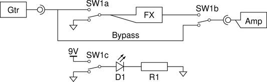
Figure 15.11 Bypass switching with indicator LED.
Guitar Pickup Selection
One of the switch types described above was the dpdt on-on-on switch. One common use for a switch like this might be in the pickup selection circuitry for a two pickup electric guitar. Three pickup configurations usually involve a selection switch with more throws, but with just two pickups the usual options are just: one, the other, or both. The wiring shown in Figure 15.12 achieves this set of options. In the top position only the neck pickup is selected, in the middle position the two pickups are paralleled together, and in the bottom position (illustrated) only the bridge pickup gets through. NC in the diagram stands for ‘no connection’.

Figure 15.12 Typical electric guitar pickup selection switch wiring for a two pickup, three way selector configuration.
Headphone Jack Switching
Switching functionality can sometimes be encountered built into other components. The commonest example of this is the switching jack. TS and TRS jacks can come in switching and non-switching varieties. These switching jacks are encountered regularly in some very common audio circuits, from headphone jacks that cut off the loudspeakers, to combined mono-stereo inputs, to patch bay semi-normalled connection points. The idea is simple enough; for each contact inside the jack, there are two terminals connected together. When a jack plug is inserted it breaks these connection as it connects itself to one of the two terminals.
The arrangement is illustrated in Figure 15.13. Before the headphones are plugged in, two pairs of contacts send the audio through to the left and right loudspeakers. Plugging in the headphones pushes the terminals apart and breaks the connections to the loudspeakers. The signal instead comes out through the jack plug, and goes to the headphone drivers.
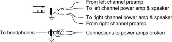
Figure 15.13 Using a switching jack to disconnect the loudspeakers when a headphone jack plug is inserted.
The same switching mechanism can be used to achieve a number of useful signal routing functions in audio equipment. Sometimes one signal is being rerouted to a different destination, as in the example here. In other cases it is a question of a new signal being switched into the signal path, replacing a previous input connection.
Power Supply Switching
Figure 15.14 illustrates a commonly utilised configuration which achieves two useful functions through the combined wiring of the input and power supply connector jacks. Firstly, on/off switching is implemented without the need for a separate switch, and second, automatic selection between battery and mains powering is achieved.
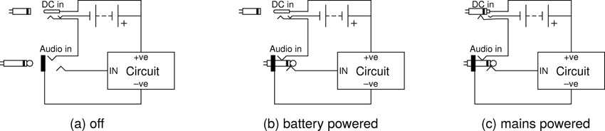
Figure 15.14 Power supply ON/OFF and source switching scheme commonly used in electric guitar effects pedals.
In situation (a) the circuit is turned off (even if the power jack were inserted). This is because the negative connection to the power supply is wired to the ring terminal of a TRS ‘Audio in’ jack. The circuit is intended to be used with a TS jack plug (i.e. a guitar lead), so the use of a TRS jack may seem odd. Recall however that in a typical circuit, the jack sleeve connection goes to ground, and this is where the power supply negative should get connected in order to complete the loop and power up the circuit.
When a standard TS jack plug is inserted into the TRS input jack the long barrel to the jack plug sleeve shorts together the TRS jack’s ring and sleeve, and thus powers up the circuit. Situation (b) shows this arrangement, with the circuit running under battery power. If a power supply is plugged into the DC input jack, this should take precedence over the battery, so a switching power jack is used for the DC input. In situation (c) a power jack plug has been inserted, actuating the switch and disconnecting the battery, allowing the circuit to get its power from the external power supply instead.
References
N. Collins. Handmade Electronic Music. Routledge, 2nd edition, 2009.
D. Self. Small Signal Audio Design. Focal Press, 2nd edition, 2015.