16 | Diodes
In Chapter 3 diodes were introduced at a theoretical level, described in the context of the semiconductor materials from which they are fabricated. Here that introduction is expanded into a more practical examination of what diodes do and how to use them. The diode is the simplest of all semiconductor devices, made (usually) by sticking two pieces of semiconductor material together, one p-type and one n-type, in order to form a p-n junction.
A diode’s two terminals are referred to as the anode and the cathode, as shown in Figure 16.1. The fundamental action which characterises the behaviour of a diode is that it allows current to flow in one direction but not the other. In the situation where a diode’s anode is at a positive voltage relative to its cathode, the diode is said to be forward biased, and current can flow. When the anode is negative relative to the cathode, the diode is referred to as being reverse biased, and no current flows.
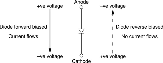
Figure 16.1 Electric current always flows from positive to negative. Diodes allow current to flow only when the anode is positive relative to the cathode. When the cathode becomes more positive, no current flows.
An ideal diode would behave as a short circuit (very low resistance) in the forward biased direction and as an open circuit (very high resistance) in the reverse biased direction. The behaviour of real diodes is a little more complex but this simplified description is often sufficient to provide an understanding of what a diode will do in a particular situation. It is however the deviations from this ideal behaviour which is of most interest in such applications as distortion effects, where diodes often find application in audio circuits. These deviations from the ideal are addressed in the following section on the electrical characteristics of diodes.
In some contexts diodes are also referred to as rectifiers. The two terms are more or less interchangeable but rectifier is most often reserved to refer to a device which can handle a comparatively large current, while diode refers to a device designed to work with lower level signals. Such diodes will sometimes be specifically referred to as small signal diodes in order to emphasise the distinction. As a rule of thumb, if it has a glass body it’s probably a small signal diode, if it has a black plastic type body, then it’s more likely to be referred to as a rectifier. In many circumstances a broad range of diodes of both types will work equally happily in a given circuit. Figure 16.2 shows some typical examples of the kinds of diodes which are commonly encountered in audio electronics. Notice that in all cases (except for LEDs) there is a stripe on one end of the body. This indicates the cathode connection of the diode.
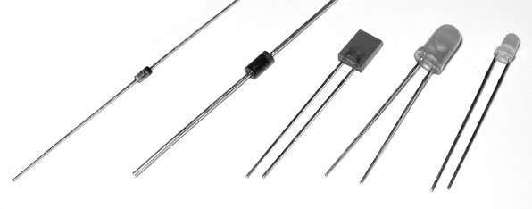
Figure 16.2 Some typical diodes: a 1N4148 small signal diode, a 1N4001 rectifier diode, and three LEDs – rectangular, 5mm round, and 3mm round.
Electrical Characteristics
As mentioned above, the simple ‘one way valve’ description of a diode, while often adequate, does not fully characterise the real world behaviour of these devices. This ideal model is indicated on the graph in Figure 16.3. In the reverse biassed condition the ideal graph runs horizontally along the negative X axis, indicating that zero current will flow no matter what the reverse bias voltage is. In the forward biassed condition the graph runs straight up the positive Y axis, indicating a zero voltage drop and unconstrained current flow.
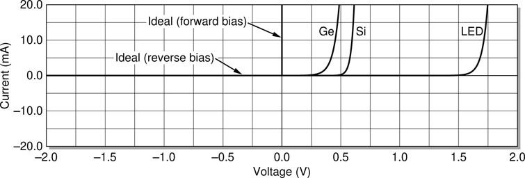
Figure 16.3 Diode i-v characteristics, showing the idealised behaviour alongside plots for germanium, standard silicon, and LED devices.
The most important deviation from this ideal model is that a real diode does not start allowing current to flow as soon as the anode voltage exceeds that of the cathode. As explained in Chapter 3, a depletion layer exists at the p-n junction which forms a barrier to current flow. It requires a certain amount of voltage in order to overcome this depletion layer. Only then can current start to flow. Even at voltages just above this switch on level current initially encounters significant resistance, and the diodes need a little more voltage in order for the graph of the current level to start climbing steeply. The three plots in Figure 16.3 illustrate this behaviour for three different types of diode.
As seen on the graph, the forward bias voltage for conduction varies between different kinds of diode. Germanium based devices start to turn on at a very low forward bias voltage, typically round about 0.3V, but they also advance more gradually as the voltage increases. Thus the Ge plot has a slightly gentler slope than the Si plot next to it (notice that the lines are slowly converging as they rise). Standard small signal Si diodes turn on more abruptly at round about 0.6V. LEDs typically need more than a volt to turn on, and the voltage varies quite a bit with different LEDs, most notably with LEDs of different colours.
Real world diode behaviour is much closer to the ideal in the reverse bias direction. All diodes do however have some small reverse leakage current. If the graph scale were expanded in the reverse bias region, the lines could be seen dropping just a little bit below the axis, indicating some slight reverse bias current flowing. Table 16.1 puts some numbers on these quantities for various commonly encountered diodes. The columns are as follows:
Table 16.1 Typical specifications for some standard diodes of various types
Part number |
Typea |
VR max |
IR max |
VF maxb |
IF max |
Ptot max |
CD max |
Package |
1N4148 |
Si |
100V |
25nA |
1.00V |
0.2A |
0.50W |
4pF |
DO-35 |
1N914 |
Si |
100V |
25nA |
1.00V |
0.3A |
0.50W |
4pF |
DO-35 |
1N4001 |
Si |
50V |
30µA |
1.00V |
1.0A |
3.00W |
15pF |
DO-41 |
1N4007 |
Si |
1000V |
30µA |
1.00V |
1.0A |
3.00W |
8pF |
DO-41 |
1N5408 |
Si |
1000V |
5µA |
1.00V |
3.0A |
6.25W |
30pF |
DO-16 |
6A6 |
Si |
600V |
10µA |
0.90V |
6.0A |
5.40W |
150pF |
R-6 |
1N5817 |
Sch |
20V |
1mA |
0.45V |
1.0A |
1.25W |
125pF |
DO-41 |
1N34A |
Ge |
60V |
30µA |
1.00V |
50mA |
80mW |
<1pF |
DO-7 |
1N270 |
Ge |
100V |
100µA |
1.00V |
40mA |
80mW |
<1pF |
DO-7 |
OA90 |
Ge |
30V |
20µA |
1.00V |
50mA |
80mW |
– |
DO-7 |
Red |
LED |
5V |
50µA |
1.80V |
7mA |
14mW |
11pF |
Ø5mm |
Blue |
LED |
5V |
10µA |
4.50V |
30mA |
105mW |
100pF |
Ø3mm |
a. Si = silicon, Sch = Schottky, Ge = germanium, LED = light emitting diode.
b. The VF max values quoted may not be as expected. VF is highly dependant on the current at which it is measured. The values given here are taken from data sheets which quote test conditions ranging from 5mA (for the 1N34A) up to 6A (for the 6A6).
Part number – the serial number used to order the part, or when searching for data sheets or general information on a particular device.
Type – the class or type of diode in question. See the table footnote for details.
Maximum reverse blocking voltage (VR max) – diodes can only take so much reverse voltage before they breakdown (and usually burn out). Note in particular that LEDs can not withstand much reverse bias voltage before breaking down (just 5V in the two examples shown here).
Maximum reverse leakage current (IR max) – as mentioned above, diode reverse blocking is not perfect. Some minimal leakage current always gets through. Mostly it is negligibly small. The 1N5817 is a notable exception at 1mA; in general Schottky diodes exhibit poor reverse leakage characteristics.
Maximum forward voltage (VF max) – the standard spec. is for when the diode is considered to be ‘fully on’, i.e. conducting a significant current. This explains the unexpectedly high values quoted for the three Ge devices. Germanium diodes are usually described as turning on at a lower voltage than their silicon cousins, but recall that they also exhibit a gentler slope on their i-v graph, and so the two types converge moving further along the graph.
Maximum forward current (IF max) – the maximum forward current the diode can handle without damage. The six silicon types are arranged in ascending IF max. The first two would generally be referred to as small signal diodes, while the latter four would be classified as rectifiers.
Maximum total power dissipation (Ptot max) – closely tracks with IF max. LEDs and germanium devices in particular can not usually dissipate very much power.
Maximum diode junction capacitance (CD max) – low junction capacitance can be important in some applications. This is one place where germanium diodes outperform their silicon counterparts. At the other end of the scale, Schottky diode tend to have fairly poor capacitance metrics.
Package – the size and shape of diodes can vary significantly. Common package outlines are illustrated in Figure 16.4.
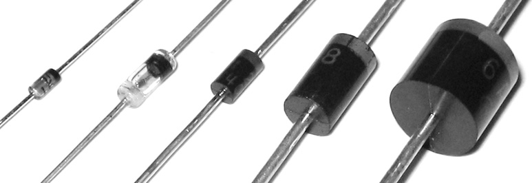
Figure 16.4 Standard diode package outlines: DO-35, DO-7, DO-41, DO-16, R-6.
Diode Types
In addition to standard diodes (small signal or rectifier) there are a number of other common types (along with quite a few more esoteric variants which are not covered here). The three variants most likely to be encountered in audio electronics are light emitting diodes (LEDs), Zener diodes, and Schottky diodes. Also of interest in the context of audio electronics are the germanium variant of standard small signal diodes. These four categories are discussed below.
Light Emitting Diodes
LEDs are very familiar as the glowing indicator lights encountered on the front panels of almost every piece of audio technology. As with all diodes, it is important to differentiate between the anode and the cathode when connecting an LED into a circuit. In the case of LEDs there are two common signifiers to look out for, indicating the cathode or negative pin of the device, a shortened leg and a flat region on the side of the LEDs body. LEDs are just diodes that emit light, and can occasionally found used in a circuit where a normal diode might be expected, rather than exclusively as a front panel indicator light. So long as the lower than usual VR max is taken into account when using an LED in a circuit, there is no reason not to try one and see how it sounds.
Zener Diodes
Of the very many special purpose diode types which exist, the most common is probably the Zener diode. Zeners are wired into a circuit in the reverse orientation to normal, and are used to provide very well defined reference voltages. While many diodes can be easily damaged or destroyed by reverse biasing them all the way to their breakdown voltage, Zener diodes are designed to operate at this point on their characteristic curve, and this is how they provide their stable voltage reference. Figure 16.5 shows the i-v characteristic curve for a three point one volt Zener diode. Its forward characteristic is more or less identical to a standard silicon diode, but in reverse bias it conducts at a specified voltage much lower than a normal diode’s VR max.
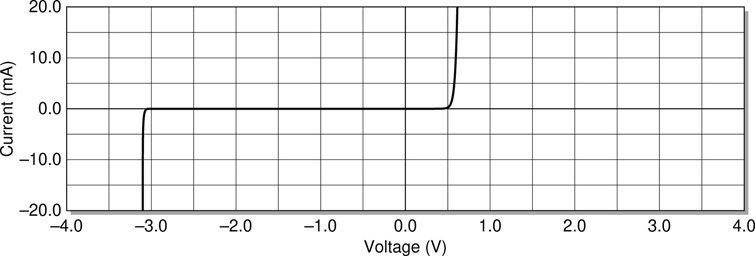
Figure 16.5 Typical i-v characteristic for a 3V1 Zener diode. Zener diodes are designed to have very specific reverse breakdown voltages. This one breaks down at −3.1V.
Zener diodes can be seen in two of the circuits included in the circuit catalogue in Appendix D. In both cases they are performing their usual job of providing a fixed reference voltage. In the phantom powered electret microphone circuit the Zener utilised is a 12V device, while a 5V1 Zener can be seen deployed in the noise gate circuit. Notice in both cases that the diode is inserted into the circuit counter to the normal diode orientation. The anode connects to the low voltage side, with the cathode wired at a point of higher potential, in order to reverse bias them and bring them into conduction at their designed breakdown voltage.
At first glance the device in the electret mic circuit may appear to be inserted the wrong way round, but notice that its top (the anode) is connected to ground, while its bottom connects through to the +48V coming into the circuit from the phantom power supply. Sometimes the layout conventions outlined in Chapter 7 on circuit diagrams are not strictly adhered to. In this instance it simply leads to a much neater schematic diagram to arrange things with the ground point in the middle of the diagram.
Schottky Diodes
Another commonly encountered type of diode is the Schottky diode. These have a low switching voltage and operate very quickly, making them ideally suited to high frequency circuits. These high switching speeds are generally of no great benefit in audio circuits which operate in a very limited bandwidth when compared to the likes of radio communications circuitry. Their low switching voltage is however sometimes used to advantage in audio circuits. The main disadvantages of Schottky diodes are their relatively large reverse leakage current and junction capacitance. They also tend to have a lower value for VR max, and so can not withstand as large reverse voltages as most standard diodes can. The specifications for the 1N5817 Schottky diode included in Table 16.1 illustrate these points well.
Schottky diodes do not actually consist of a standard p-n junction as standard diodes do, but rather are formed by the junction of a semiconductor with a metal. This is what gives them their low forward voltage drop and fast switching action. A silicon diode has a typical forward voltage of 600–700mV, while the Schottky’s forward voltage is usually in the range 150–450mV. This lower forward voltage requirement allows higher switching speeds and better system efficiency. A Schottky diode can be seen employed in the low power audio amplifier circuit in Appendix D. Here advantage is being taken of its low switching voltage. It is being utilised as a reverse voltage protection measure (the 386 IC in this circuit is easily damaged by reverse polarity power connection). The low forward voltage drop means that as little voltage as possible is lost to the rest of the circuit in normal operation. There are certainly better reverse polarity protection measures which could be employed, but this has the advantage of being trivially simple to implement.
Germanium Diodes
These days diodes are almost exclusively made from silicon (Si) semiconductor material, but germanium (Ge) based diodes used to be much more common. While germanium semiconductors have fallen out of general usage in most electronics applications due to their poor performance in most respects when compared to their silicon equivalents, some audio circuits call specifically for germanium diodes for their particular sonic characteristics. In particular, many distortion circuits specify (or at least suggest) Ge diodes. The gentler slope of their i-v characteristic curve means that they can produce a softer distortion effect than their silicon counterparts. Silicon diodes switch from fully off to fully on over a very small voltage range and as such the clipping they introduce can be very harsh. Germanium diodes provide a slightly gentler alternative.
Their very low initial conduction voltage relative to silicon devices also makes them better suited when dealing with very low level signals. A small signal might be all but used up by the time it has managed to switch on a silicon diode, but the same signal will be able to drive a reasonable amount of current through a germanium device. Sometimes a Schottky diode would also work well in such applications, however the much larger junction capacitance of a Schottky can often rule them out, making germanium devices the best option.
Schematic Symbols
The circuit diagram symbol used to signify a standard diode is an arrow with a line at its end, as shown in Figure 16.6a. The arrow indicates the direction in which current is allowed to flow, while the line represents the fact that current is prevented from flowing back in the other direction. A number of variations on this basic symbol also exist, used for showing various special types of diode. Those corresponding to the diode types described earlier are included here, others exist, used to represent some of the additional, less common types which might occasionally be encountered.
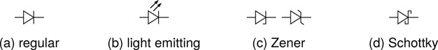
Figure 16.6 Diode circuit symbols for the diode types most commonly encountered.
The symbol in Figure 16.6b indicates an LED (the two arrows represent light coming out of the device), while Figure 16.6c shows two different variants which are both used to represent Zener diodes. Figure 16.6d shows the symbol usually used to signify a Schottky diode. In all cases the connection on the left hand side of the symbol is the anode, and connection on the right hand side is the cathode. Remember however that Zener diodes will usually be connected into a circuit with their anode at the lower voltage side rather than the usual way around for the other diode types.
Circuits
Diode Current Limiting Resistor
When wiring up an LED as a standard indicator light as shown in Figure 16.7, a current limiting resistor is always needed. The value of the resistor depends on three things, the voltage drop and working current of the LED, and the DC voltage level which will power the circuit. Once these are known, the optimum resistor value can be calculated. This value is then usually rounded down to the nearest E12 standard resistor value.

Figure 16.7 How to choose a suitable current limiting resistor for an LED.
Typical values for a standard red LED might be something like 2.1V and 20mA for normal operation. Details will be found in the manufacturer’s data sheet for the specific device to be used. If a 9V power supply is to be used then the calculation proceeds as follows.
Step 1: Voltage across resistor: VR1 = Vtotal − Vdiode = 9 − 2.1 = 6.9V
Step 2: Value of resistor:
Step 3: Next largest E12 value: R1 = 390Ω
Reverse Polarity Protection
Some components can be damaged if power is inadvertently connected to a circuit the wrong way round. Various approaches can be taken to mitigate or prevent any potential problems. One of the simplest solutions is to connect a diode in series with the power supply. If the connections are reversed, the diode will be reverse biased and no current will flow, thus saving components from potential damage. The down side to this simple solution is that the voltage dropped across the forward biased diode in normal operation is lost to the circuit it is protecting.
In order to minimise the impact, the circuit shown in Figure 16.8 indicates a Schottky diode as opposed to a standard silicon diode. As has been explained, the Schottky diode has a lower forward voltage drop than the more common silicon diode, round about 0.3V, versus about 0.7V. This may not seem like much, but when a circuit is powered from a small power supply of maybe 5V or even 3.3V, as some are, it can make all the difference. For even lower insertion losses the MOSFET solution presented in Chapter 17 can be used.
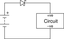
Figure 16.8 Rudimentary reverse polarity protection using a Schottky diode.
Diode Ring Modulator
One of the most widely recognised diode circuits (by name if nothing else) is the classic diode ring modulator circuit (Figure 16.9). The circuit takes its name from the ring of diodes at the heart of the circuit. The ring modulator combines two input signals, effectively multiplying them together. This can produce a rich mixture of harmonic and anharmonic frequency components in the output signal, which can result in interesting metallic and bell like sounds. The right combination of inputs are needed in order to obtain really good results, and the signals levels need to be well balanced for best effect.

AC to DC Power Supply Circuit
This circuit has some visual similarities to the ring modulator of the previous section, but it is completely different. The most important thing to notice is that, although there are again four diodes in a loop, here they do not form a ring, but rather a bridge. Notice that in the ring modulator ring the four diodes chase each other’s tails around the circle. Here, on the other hand, the four diodes all flow left to right. This means that the loop here operates in a very different way. The configuration is called a bridge rectifier, and as Figure 16.10 illustrates, it takes the bottom half of an AC signal and folds it back up on itself. This process is called full wave rectification, and is described in Chapter 5: Signal Characteristics.
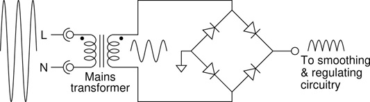
Figure 16.10 A diode bridge rectifier in a standard power supply application.
The circuit shown in Figure 16.10 is the business end of a typical linear power supply circuit. The transformer takes in mains voltage and converts it down to a more user friendly level. The bridge rectifier then full wave rectifies it. This is usually followed by a large smoothing capacitor and possibly a regulator circuit, to turn it into a nice steady DC voltage ideal for powering DC circuits.
An variation on this circuit, using a transformer with a centre tap output, allows the four diode bridge in Figure 16.10 to be replaced with just two diodes to achieve the same full wave rectified result. Penfold (1994) closes with a simple mains power supply project which uses this approach. It adds a large 1000µF smoothing capacitor, followed by an LM317 based regulator circuit similar to Figure 18.9, to produce a well regulated DC power supply suitable for powering most of the circuits in this book.
References
J. Falin. Reverse Current/Battery Protection Circuits. Texas Instruments, 2003.
Maxim. AN 636: Reverse Current Circuitry Protection. Maxim Integrated Products, 2001.
R. Penfold. Practical Electronic Musical Effects Units. Bernard Babani, 1994.
A. Sedra and K. Smith. Microelectronic Circuits. Oxford University Press, 7th edition, 2014.