
9 Digital Signal Processing Subsystem Design (Example)
9.1 General Statements
In this chapter we consider and discuss the main stages of system design of the digital target return signal processing subsystem employed by a complex surveillance radar system using a phased array. However, this is not considered a practical case. Preliminarily, we will discuss some general considerations associated with the designing and construction of a digital target return signal processing subsystem, particularly in the context of an automated complex “radar-digital signal processing and control subsystem” (complex radar system or CRS).
The basic idea of any CRS digital signal processing and control subsystem is defined, first of all, by the type and purpose of the CRS. Before starting the designing process, at the initial stage of analysis of the problems to be solved by a higher-order system, the specifications of the corresponding CRS support must be first defined. The first step will be to consider and select which type of CRS to construct, including type of radar to be used; thus it is critical to define the problems typically associated with digital signal processing and control subsystems and embark on a design process that is prepared to solve the many problems that might arise during the design and construction of the subsystem. At the same time, there is a need to adhere to the following principal positions. The CRS, as a source of information, is very complicated and expensive. It is designed and constructed in a way to ensure compliance of the highly technical specifications that form part of the design procedure. Evidently, the CRS digital signal processing and control subsystem must be able to stabilize the radar performance under hard conditions that involve high-precision operations and applications.
From the viewpoint of automated CRS digital signal processing and control processes, we can distinguish between the automatic and automated radar systems. The automatic radar systems are required, for example, to monitor the air condition in regions that are difficult to access. However, the complete automatization of digital signal processing and control subsystems is worthwhile in the case of CRSs operating in global systems on control, earth-based guidance and tracking, landing, and so on. In doing so, all available methods and tools to cancel the interference and noise must be used. The digital signal processing and control subsystem must be able to keep stable the probability of false alarm to prevent overloading on the central microprocessor system. If it is found that complete automation of a CRS is not worthwhile or impossible on account of specific technical or tactical considerations, then keeping such requirements in mind, different types of systems are designed customizing the system to meet specific requirements, especially where some of the processes are manually carried out by an operator, for example, even signal processing and other specific controls. For example, the operator is responsible for blanking the intensive interference and noise zones, primary target lock-in with the purpose of target tracking, switching on the security equipment and tools of interference and noise protection, semiautomatic target tracking, and so on.
The level of development and production status of the digital computing system element base are critical for effective designing and construction of the digital signal processing and control systems. By this, we only mean computer-driven applications deployed to solve specific problems encountered in the signal processing and control, not computer techniques in general. Thus, there is increased interest in a new element base, namely, graphene.
While designing a specific digital signal processing and control system, theoretical and technical investigations on signal processing methods and algorithms, the technical team, including engineers and subject experts, communications skills, and so on play a very important role.
9.2 Design of Digital Signal Processing and Control Subsystem Structure
9.2.1 INITIAL STATEMENTS
In accordance with the basic idea, let the designed CRS be assigned for air target detection and tracking with a highly effective reflective surface Stg > 1 m2. Scanning area is omnidirectional. The maximum radar range is Rmax < 150km (T = 1 ms). Information is presented to users via the smoothed polar coordinates and , the target course , and the velocity scalar of vector Vtg. The accuracy of smoothed coordinates and parameters are σp = 500m, σβ = 0.5°, σQ = 2°, and σV = 50m/s.
The CRS must distinguish the targets from the background of passive interferences with the coefficient of distinguishability that is sufficient for target detection and target tracking while the target and passive interference are resolved. Moreover, the system must be able to detect a stationary target, or a moving target with the so-called blind velocities, for which fD = kT−1 (k = 1, 2, …). The problem with detecting the target at the border of scanning range with the probability of detection PD = 0.95 is set within the time limits of 15 s. The probability of target-tracking failure within the limits of scanning range is Pfailure < 0.05. The maximum number of targets tracking simultaneously is Ntg = 20. All CRS operations, namely the target detection, the lock-in for target tracking, and the target tracking by trajectory, must be automated completely. The reliability control measures allowing the CRS to operate without a regular labor force must be provided.
The first stage of any radar system design involves the selection of radar structure and energy parameters constituent of a CRS. The radar antenna type, shape and width of radar antenna directional diagram, method and period of scanning coverage, transmitter power, duration and scanning signal modulation technique, period of scanning pulsing, resources and methods needed for protection of the system from active interferences, and other radar parameters must be defined and justifed at this stage. Thus, as a result of the first-stage activities, we have the following:
The cylindrical antenna is selected as the transmit-receive antenna, which makes discrete scanning possible as facilitated by the radar antenna’s directional diagram beam in omnidirectional scanning mode. The radar antenna directional diagram beam is fan-shaped in the vertical plane and covers all scanning range by tilt angle. The radar antenna directional diagram beam width in the horizontal plane is θβ = 3°. Scanning resolution is equal to 2.5°. The number of fixed positions of the radar antenna directional diagram under the omnidirectional scanning is equal to 144. The omnidirectional scanning period is Tscan = 4.5 s.
The linear-frequency-modulated pulse with duration τscan = 64 μs and spectrum bandwidth Δfscan = 0.5 MHz is considered as the scanning signal. The scanning signal base is τscanΔfscan = 32. Duration of the compressed signal at the GD output is .
The power of scanning signal is selected in such a way that each direction is scanned by the pulse bursts consisting of 30 pulses divided on groups, each of 10 pulses at three convertible in series frequencies f01, f02, f03 diverging on the constant interval Δf0 to satisfy the required signal-to-noise ratio (SNR). The coherent accumulation of reflected signals for each group of 10 pulses and the noncoherent accumulation of corresponding total signals in each resolution element by radar range, azimuth, and Doppler frequency between groups must be provided.
Note that specific magnitudes of some radar parameters are presented here only because they are directly used in the designing and construction of a CRS digital signal processing and control subsystem.
At the second stage, the design process involves the following key steps: specifics related to the CRS structure are firmed up, the parameters of digital signal processing subsystem are justifed, and the ways of specific realizations are defined. Foremost, the main problems and tasks of digital signal processing and control subsystem should be discussed and the procedures to solve these problems should be defined.
9.2.2 MAIN PROBLEMS OF DIGITAL SIGNAL PROCESSING AND CONTROL SUBSYSTEM
The task of running a CRS operation in automatic mode is carried out based on the data gathered at the initial stage of designing. Successful running of this operation is foremost achieved by high-quality cancellation of the passive interference formed due to reflections from the underlying surface, local objects, and hydrometeors. It is universally accepted that in the automatic mode the coefficient of cancellation ηcan of the passive interference caused by reflections from the underlying surface and local object should not be less than 50 dB and, by reflections from the hydrometeors, it should be approximately 30 dB.
To cancel the passive interference, the moving target indicator systems based on the rejector filters with interperiod subtraction of the order ν are widely used. However, in the case of high-density nonstationary passive interferences, the moving target indicator systems based on the rejector filters with the interperiod subtraction of the low order, ν = 2/3, cannot ensure the required SNR at the output. Using the moving target indicator systems based on the rejector filters with the interperiod subtraction of the high order ν increases blind velocity zone that adversely affects the detection performance, especially for targets moving in directions tangential to the radar antenna directional diagram main lobe. The coherent signal processing technique of target return pulse bursts is effective for improving the detection performance of moving targets and decreasing the rate of stimulation of blind velocities. This signal processing method can be carried out using the fast Fourier transform (FFT) processors or filters. Thus, it is worthwhile to use the rejector filters with the interperiod subtraction of the order ν and the filters of coherent accumulation in the form of FFT processors or filters in series to ensure the required quality of passive interference cancellation and, thus, better performance in detecting moving targets.
The number of pulses in the scanning pulse burst at each of the three carrier frequencies f01, f02, f03 is defined based on the condition to use the rejector filters with the interperiod subtraction of the order ν = 2 and 8-point FFT for coherent accumulation of target return signals within the limits of the pulse burst in the digital signal processing subsystem. In this case, the noncoherent accumulation of target return signals of three pulse bursts for each resolution element by radar range and for each Doppler channel must be provided. Variations in the carrier frequency of scanning pulses from burst to burst lead to a corresponding shift in the Doppler frequency of moving target return signals. The main effect of this shift is that the task of identifying the return signals from the same target becomes difficult, particularly because these return signals can appear in different Doppler channels. Thus, to eliminate this shift in the Doppler frequency of return signals from the same target at different channels of frequency, we need to select the period of scanning signals at each pulse burst in such a way that the following condition
could be satisfied. Actually, at Vtg = const for each frequency f0i, the Doppler frequency is defined as
On the other hand, the maxima position of the impulse response from the N-channel FFT processor or filter depends on the scanning pulse frequency
To ensure the coincidence of the Doppler frequency with the tuning frequency of the lth channel, the following inequality needs to be satisfied:
At l = constant, the first part in (9.4) is the constant value and the condition f0i T = const follows.
As noted in Chapter 3, to decrease the side-lobe level of amplitude-frequency characteristic of the Doppler channels, the signal weighting at the output of the FFT processor or filter is applied using the windows with the symmetric negative-going to end characteristics. In practice, the Hemming window is often used for signal weighting [1], wherein the computation of weighted signal readings at the in-phase and quadrature channels at the FFT processor or filter output is carried out as shown in the following algorithm:
where
is the weighted signal at the output of lth Doppler channel
fl−1,fl, fl+1 are the nonweighted signals at the outputs of l − 1th, lth, and l + 1th Doppler channels, respectively
In this case, the signal weighting based on the algorithm given by (9.5) is carried out at the Doppler channels with l = 2−6. Further, there is a need to note that the FFT processor or filter accomplishes the coherent accumulation of target return signals if the targets move with zero radial velocity, which makes the target detection an easy task.
Maintaining stability of the probability of false alarm is also an important task. The use of adaptive threshold control under signal detection is a practice commonly followed in solving this problem. The functioning principle of adaptive detector at the FFT processor or filter Doppler channel output is as follows. Estimation of the interference and noise variance inside the moving window of the width −0.5 to 0.5 m is defined at the outputs of all Doppler channels, excluding the zero Doppler channel, by the following formula:
where i is the number of radar range resolution element with respect to signal element, for which the average power level of interference and noise is estimated (the signal element is the central one);
is the squared amplitude envelope of the signal at the cell ij, and j = 0.5m,…, MR − 0.5m, where MR is the number of discrete resolution elements by radar range. As we can see from (9.7), under averaging we do not take into consideration the signal cell and the neighboring cells at right and left. This action is directed to suppress the effect of signal peak and the first signal side lobes on the estimation of interference and noise variance.
The interference and noise map is formed for zero Doppler channel [2–4]. The interference and noise map is a characteristic of the average by the set of power observations of the signals reflected by the underlying surface and local objects for each resolution element by radar range and azimuth. This map is stored by the specific memory. The current magnitude of the interference and noise power at zero Doppler channel is defined by signals forming at the output of the Doppler channel for zero velocity. Periodical, with interval equal to the scanning period, update of the interference and noise map is carried out by rearranging the previously averaged and current power of interference and noise for each resolution element by radar range and azimuth, for example, using the formula for exponential smoothing.
Detection of targets with zero or very low radial velocity is made employing the interference and noise map. Target return signals for these targets will appear and accumulate at zero Doppler channel. The detection threshold for each resolution element by radar range R and azimuth β is formed taking into consideration the average power of signals reflected by the underlying surface and local objects. If the signal reflected by the slowly moving target or target moving with the blind velocity exceeds this threshold, this signal will be detected.
Thus, adaptation of the interference and noise power can maintain the stability of false alarm probability while detecting target return signals, but, in this case, the average number of false detections is not controlled and can be estimated only during the simulation and digital signal processing and control subsystem sample debugging.
The next topic to be discussed involves the following: automatic target lock-in, target trajectory tracking, and target trajectory reset. Given the technical specifications, the number of target tracking trajectories, Ntg = 20, and the probability of target trajectory tracking without reset, Ptt ≥ 0.95, can be considered as a moderate mode. However, if the radar system has to function on the automatic mode under conditions of high-level interference, it entails prevention of over-loading at the digital signal processing subsystem specifically in the context of nondetection of moving targets or detection of false targets. To thwart such effects, the following measures are recommended:
Effective algorithm to detect the target trajectories providing the methods and procedures to decrease the probability of false target track beginning
Selection of target pips in target tracking gates, taking into consideration the high density of false target pips
Filtering the target trajectory parameters providing tracking of both nonmaneuvering and maneuvering targets
Implementation of specific algorithms of target classification providing a selection of the most important targets for target tracking
Ensuring speed of operation and better utilization of resources such as memory capacity of central computer system
When the radar system operates under automatic mode, it is important to ensure effective control of the radar system as a whole and functional synchronization of all elements, with the central micro-processor system. Algorithmic designing and realization of digital signal processing and control subsystem are specific tasks under construction of central computer system.
We have just considered only the main types of subsystems of the CRS central computer system. Naturally, other subsystems or constituents of the central computer system also play an important role in functioning, for example, the digital signal processing and control subsystem, the subsystem to communicate with users, and so on. However, given the limited scope and space in this chapter, it is not possible to discuss in detail the features and operations of all subsystems inherent to the radar system.
9.2.3 CENTRAL COMPUTER SYSTEM STRUCTURE FOR SIGNAL PROCESSING AND CONTROL
The principle of signal processing is divided into several stages: coherent digital signal preprocessing, noncoherent digital signal preprocessing, and digital signal reprocessing used as a basis for designing the structure of digital signal processing and control system of the radar complex. In addition, individual elements of the central computer system can be considered as subsystems to be used for the signal processing in cases, for example, of the “native-foreigner” mode subsystem and CRS control. Taking into account these considerations, an example of the structure of global digital signal processing and control system is provided in Figure 9.1. We see that the following subsystems solving the direct problems of digital signal processing and control (the rectangles with bold lines) and carrying out the transmission, receiving, and preliminary signal processing are the constituents of the global digital signal processing and control system. Data flow is represented by continuous lines and the interaction between subsystems is shown by dashed lines. Each subsystem included into the structure of the global digital signal processing and control system solves the following problems:
The digital coherent target return signal preprocessing subsystem:
Matched filtering and compression of the linear-frequency-modulated pulses
Double interperiod subtraction of the target return signals by rejector filters
Eight-point FFT of target return pulse bursts
Weighting of target return signal amplitudes at the FFT processor or filter output
Definition of target return signal amplitudes at each resolution element by radar range
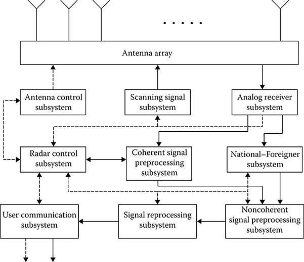
FIGURE 9.1 Global structure of the digital signal processing and control subsystem employed by the radar complex.
The digital noncoherent target return signal preprocessing subsystem:
Noncoherent accumulation of target return signals of the three processed pulse bursts in the corresponding cells
Corrections of the map of passive interferences formed by reflections from the under lying surface and local objects
Adaptive detection of target return signals
Estimation of target range
Estimation of target azimuth
The digital signal reprocessing subsystem:
Detection of target tracks
Tracking the detected target trajectories
Estimation of coordinates and parameters of moving target trajectories
Estimation of target importance
Providing information to the user
Digital subsystem of CRS control provides detailed and prompt information:
Control of the CRS switching on
Variation in scanning pulse frequency
Control of the radar antenna directional diagram beam
Control of the detection thresholds and so on
The control signals are generated both in real-time and in asynchronous mode to control the system operation, the request “native-foreigner” mode subsystem, and so on. Furthermore, the foregoing list of subsystems will be discussed and considered in more detail.
9.3 Structure of Coherent Signal Preprocessing Microprocessor Subsystem
The digital coherent signal preprocessing subsystem ensures an interface between the analog receiver linear tract and the central computer system of radar complex. The following important operations are carried out by the digital coherent signal preprocessing subsystem:
Analog-to-digital conversion
Signal detection based on the generalized approach to signal processing in noise of linear-frequency-modulated target return signals
Suppression of passive interferences
Coherent accumulation of target return signals
Data provision to assist with solving the problems of stabilization of the probability of false alarm
The digital coherent signal preprocessing subsystem is realized by an individual microprocessor sub-subsystem or a distributed set of specific microprocessor sub-subsystems.
A key part of the design process involves the design and construction of the digital coherent signal preprocessing subsystem and justification of structure of the corresponding microprocessor sub-subsystem or set of microprocessor sub-subsystems. Further, we assume that the following alternatives are key to designing and constructing the digital coherent signal preprocessing microprocessor subsystem:
Design and construction of specific microprocessor sub-subsystem based on very-large-scale integration (VLSI) circuits
Microcomputer based on a set of microprocessor sub-subsystems
Specific processor based on analog charge-coupled device components
The use of microcomputer based on a set of microprocessor sub-subsystems is not worthwhile because these cannot satisfy the functional requirements when the speed of operation takes priority, for example, during conditions requiring matched filtering and compression of linear-frequency-modulated target return signals. Microprocessor sub-subsystems with analog-to-digital conversion based on charge-coupled devices, in principle, may satisfy the main requirements on speed of operation and low power consumption, but, at the current level of research, the main elements of the digital coherent signal preprocessing subsystem, for example, the GD linear tract filters, have not been studied thoroughly. Thus, an effective alternative is the digital coherent signal preprocessing subsystem designed based on VLSI microprocessor sub-subsystem.
It is worthwhile to employ hardware in the specific digital coherent signal preprocessing subsystem designed based on VLSI microprocessor sub-subsystem to solve the following problems:
Signal detection based on the generalized approach to signal processing in noise
Suppression of passive interferences
Computation of target return signal amplitudes
Estimation of interference and noise power
To solve the problems of Doppler filtering it is worthwhile to implement the FFT processor or filter using the effective and simple realization methods and procedures of complex multiplication. All elements of the specific digital coherent signal preprocessing subsystem designed based on VLSI microprocessor sub-subsystem must possess high reliability and low power consumption. High reliability can be ensured by equipment reservation or information redundancy. Low power consumption can be achieved by very careful circuit designing and implementation of VLSI with small power dissipation.
Now, consider an interaction between the elements of the specific digital coherent signal preprocessing subsystem designed based on VLSI microprocessor sub-subsystem (see Figure 9.2) and discuss the principles of realization of the main objectives of digital coherent target return signal preprocessing subsystems and the main technical specifications of hardware.
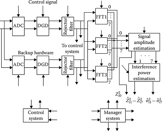
FIGURE 9.2 Structure of the specific microprocessor subsystem for coherent signal processing.
The first element of the global structure of digital coherent target return signal preprocessing subsystem is the analog-to-digital converter (ADC) of target return signals at the phase detector output. Because the duration of the compressed linear-frequency scanning signal is , the limiting frequency of sampling in time must be fs = 500 kHz both for in-phase and quadrature channels. However, to improve the digital GD (DGD) characteristics it is worthwhile to increase this frequency, at least twice, that is, fs = 1 MHz (see Chapter 2). The number of amplitude quantization bits is selected based on linear transformation of the target return signals exceeding the receiver noise on 50-60 dB. For this purpose, we need to use 10-bit ADC and/or ADC with capacity of more than 10 bits. Thus, ADC must issue the signal codes at the outputs of in-phase and quadrature channels with resolution τs = 1μs and capacity Ncapacity = 10 bits.
Next element of the total structure of digital coherent target return signal preprocessing subsystem is the DGD for linear-frequency-modulated target return signals that can be realized in time domain employing the nonrecursive filter or in frequency domain using the FFT processor or filter. In doing so, while using the sequential scheme of DGD in time domain to compute a single magnitude of the output signal, we need to use 4fsτscan = 4 × 1 × 64 = 256 multiplications and 252 additions. Consequently, the required speed of operation of DGD is equal to 256 × 106 multiplications per second, which is very difficult to realize. Under realization of DGD in frequency domain we obtain some benefits in speed of operations (see Chapter 2), but these benefits are not so essential that we could use them without any doubts.
To improve the DGD speed of operation we can use properties of parallelism of matched filtering algorithms. For this reason, to realize DGD with high speed of operation we can use the parallel mixers based on ROM, parallel adders with simultaneous addition of several numbers, and parallel registers. For example, for parallel nonrecursive digital filter, coincidence-type adders, and parallel registers the minimal time of convolution both in the in-phase channel and in the quadrature channel is 75 ns. For a four-channel DGD (see Figure 2.7) the minimal time to obtain a single magnitude of the output signal is 100ns.
The nonrecursive smoothing filter with short impulse response is placed after DGD. The main tasks of this filter are, first, to suppress the signal side lobes at the DGD output and, second, to decrease the sampling rate to the frequency corresponding to the sampling theorem requirements. Decrease in the sampling rate in m times (m is the integer) is carried out by the element providing a sample of each mth element from the sequence of input sampled target return signals {x(kTs)}. As a result, we obtain the output signal {x(kmTs)} with the sampling period . Naturally, the sampling period must satisfy the following condition:
both at the in-phase channel and at the quadrature channel.
The cancellation of correlated interference is realized after the signal detection based on the generalized approach to signal processing in noise. For this purpose, the samples of in-phase and quadrature channels in each resolution element by radar range (the number of resolution elements by radar range is MR = 500) are stored during 10 periods by the buffer memory with capacity of QBM = 2 × 500 × 10 = 104 of 10-bit words. After that, 10-pulse bursts corresponding to each resolution element by radar range are processed by the rejector filters with the interperiod subtraction of the order ν = 2 individually both in the in-phase channel and in the quadrature channel. Owing to the simplicity of the rejector filters with the interperiod subtraction of the order ν = 2 algorithm, its realization in real time is not difficult. Thus far, we have considered and discussed operations during the first stage of digital coherent signal processing. To ensure the required reliability, all hardware elements of the first stage must be doubled. The output signals of the main and reserved hardware set are compared by a specific module. Comparison results are used both by the searching system and by the default system.
Signals at the outputs of the rejector filters with the interperiod subtraction of the order ν = 2 in the form of 8-pulse bursts come in individually by the in-phase and quadrature channels at the input of filter carrying out a coherent accumulation of the target return signals within the limits of 8-pulse bursts. In the considered case, the target return signal coherent accumulation is realized in the frequency domain using the FFT processors or filters. Using the FFT processor or filter is the most appropriate choice considering the simplicity of usage and tuning convenience while processing pulse bursts with variable width. Information at the FFT processor or filter output is accumulated during eight scanning periods, that is, 8 × 10⁻³ s, Tscan = 10−3 s. The number of resolution elements by radar range is MR = 500. Consequently, 8-point FFT must be finished within the limits of 16|Lts. With current level of technology, it is possible to use different schemes of FFT realization that guarantee faster operations without any problems. Moreover, to increase the efficiency of coherent signal processing and the reliability of its corresponding hardware module, three FFT processors or filter in series with the time are required, as shown in Figure 9.3. This functional capability of FFT processors or filters reduces requirements for faster operation of FFT processors or filters and for the high reliability of the corresponding hardware module.
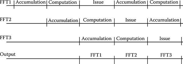
FIGURE 9.3 Timing diagram for three FFT processors.
Each FFT processor or filter possesses a buffer memory to store the input data. The buffer memory capacity must store the 8-pulse burst signals at each of the 500 resolution elements by radar range and take into consideration the in-phase and quadrature channels, that is, QBM = 2 × 8 × 500 = 8 × 10³ 10-bit words. At the FFT processor or filter output, the signal weighting at the Doppler channels 2–6 is carried out to reduce the effect of signal side lobes and expand zero part width of amplitude-frequency characteristics of Doppler filters. Weighting is carried out based on the algorithm given by (9.5). By this operation, the coherent signal processing is concluded, and the envelope amplitude of target return signals needs to be selected, for example, to unify signals at the outputs of in-phase and quadrature channels.
Estimation of envelope amplitudes at each resolution element by radar range for all Doppler channels is to be carried out in accordance with signal processing algorithms discussed in Chapter 3. Estimations of squared envelope amplitudes obtained in the zero Doppler channel are used to make corrections in the interference and noise power map. Estimations of squared envelope amplitudes obtained in other Doppler channels come in at the input module of definition and estimation of interference and noise power. For this purpose, the signal processing algorithm used to estimate the sampled interference and noise variance within the limits of the window, including eight resolution elements by radar range (approximately 2.5km) from both sides of the central (signal) element given by (9.6), is realized. Estimations of sampled interference and noise variance are defined at the outputs of each Doppler channel, except for zero Doppler channel. The corresponding magnitudes of squared amplitudes and variances are transmitted to the noncoherent signal preprocessing subsystem.
9.4 Structure of Noncoherent Signal Preprocessing Microprocessor Subsystem
9.4.1 NONCOHERENT SIGNAL PREPROCESSING PROBLEMS
Based on the global structure of the digital signal processing and control system employed by radar complex (see Figure 9.1) the noncoherent signal preprocessing subsystem solves the following problems:
Noncoherent accumulation of signals after coherent signal processing of each from three 8-pulse bursts by the FFT processor or filter. Accumulation can be presented by adding the squared envelope amplitudes at each ijth cell (i = 1, 2,…, MR—are the numbers of discrete elements by radar range; j = 0, 1, …, 7—are the numbers of Doppler channels). Total number of such cells is MR = 500 × 8 = 4000. Addition of two numbers by specific central computer system requires 3-5 reduced arithmetical operations. To exclude the information losses, the noncoherent accumulation of signal containing the next pulse burst must be done within the limits of coherent signal preprocessing of subsequent pulse bursts, that is, in our case, within the limits of 8th scanning period (8 ms).
Noncoherent accumulation of interference and noise power estimations for all Doppler channels, except for zero Doppler channel, and for all resolution elements by radar range. Noncoherent accumulation of the interference and noise estimations is carried out analogously as the noncoherent accumulation of signals and requires approximately the same level of central computer system performance.
Corrections of the interference and noise map. This map is stored by the specific noncoherent signal preprocessing microprocessor system memory and holds the average estimations of the squared signal amplitudes received by zero Doppler channel for each resolution element by radar range and for each azimuth direction. Periodical update of these estimations, including the period of air surveillance, is carried out using the signals obtained at the Doppler channel for zero velocity output by the following formula:
where
is the previous estimation of squared signal amplitude at ith resolution element by radar range at lth azimuth direction
is the squared signal amplitude on the next (n th) update step derived based on the data of three Doppler zero velocity filters at ith resolution element by radar range at lth azimuth direction
ζ is the smoothing coefficient, as a rule ζ = 0.2–0.3
In the case of a single realization of the signal processing algorithm given by (9.9), two multiplications on the constant and one addition are required. Taking into consideration all nonarithmetical operations, the total number of reduced arithmetical operations will be for about 10. If the radar antenna directional diagram beam is delayed at each azimuth direction on 24 ms (3 × 8 ms) and the only string of the interference and noise power map is updated (500 cells), we can assume that the operation on updating the interference and noise power map is not critical for designing the specifications of the noncoherent signal preprocessing microprocessor system.
Forming the adaptive detection thresholds. To form the detection thresholds we can use the interference and noise power estimations at Doppler channels 1-7 and the average signal power estimations at each Doppler zero channel (the interference and noise power map) estimations. Formation of thresholds to detect the signals received by all Doppler channels except for Doppler zero channel is carried out based on the current magnitudes of variance estimations for each resolution element by radar range and Doppler frequency. Threshold is formed by multiplication of on the coefficient α1 defined based on the requirements of the probability of false alarm. Forming the thresholds for signals received by the Doppler zero channel is carried out by multiplication of corresponding magnitude of the interference and noise power map on the coefficient α2 defined based on the requirements of the probability of false alarm for the target with zero velocity—this probability of false alarm can differ from the admissible probability of false alarm for moving target.
Signal detection is provided by a comparison between the signals and their corresponding thresholds computed for each cell “radar range-Doppler frequency.” To reduce the number of references to the interference and noise power map, the received signal of Doppler zero frequency channel is first compared with the constant threshold defined based on the permissible magnitude of the probability of exceeding the receiver noise power by this signal. If exceeding takes place, then the threshold is computed using the interference and noise power map and the signal is compared with the threshold. As a result of this comparison with the thresholds, we can observe one or several signals exceeding the detection threshold at some resolution elements by radar range. For a single realization of threshold formation and generalized signal detection algorithms one multiplication on the constant value and one comparison of two magnitudes are required. In doing so, the number of computer operations does not exceed 7-8. Within the limits of a single period of duration of 24 ms, 4000 realizations of the generalized signal processing algorithms must be done.
Estimation of the target azimuth by a set of signals exceeding the detection threshold at three neighboring positions of the radar antenna directional diagram by azimuth. For this purpose, at first, we need to select signal groups exceeding the detection threshold and related to the same radar range. If there is a single signal that exceeds the detection threshold into the group, then the target azimuth is defined by azimuth direction of this signal. If there are two or three signals that exceed the detection threshold into the group, then, at first, we need to choose the greatest signal, that is, the signal with maximum amplitude. The azimuth direction of this signal is β[i]. Azimuth adjustment can be provided taking into consideration a single additional side signal using the following formula:
where Zi is the amplitude of maximum signal;
φ(ϑ) is the function characterizing the shape of radar antenna directional diagram.
For a single realization of the generalized signal processing algorithm given by (9.10) through (9.12) about 30 reduced microprocessor operations are required. For this purpose, the duration required is 24 ms. The number of realizations per cycle is the random variable characterizing the possible number of targets at three azimuth directions close to each other. The problems considered and discussed so far related to the noncoherent signal preprocessing and are solved using the corresponding partial signal processing algorithms. The total partial generalized signal processing algorithm is the global noncoherent target return signal preprocessing algorithm.
9.4.2 NONCOHERENT SIGNAL PREPROCESSING MICROPROCESSOR SUBSYSTEM REQUIREMENTS
In contrast to the coherent signal preprocessing algorithm, all main operations of the noncoherent signal preprocessing are programmable and cyclical by periodicity. Each problem of the noncoherent signal preprocessing possesses its own cycle, and, consequently, specification of speed of the microprocessor subsystem operation differs from other microprocessor subsystems used by the CRS. The microprocessor of highest throughput is required to fulfill the noncoherent target return signal accumulation. The period of this operation is equal to the period of the coherent target return signal preprocessing, that is, Tcycle = 8 ms. The addition of previous sums with new magnitudes of target return signal amplitudes must be carried out at 500 × 8 = 4000 cells of “radar range-Doppler frequency” complex within the limits of 8 ms. The number of elementary operations of single summation is equal to 3, for example. Then, within the limits of 8 ms there must be 4000 × 3 = 12 × 103 operations per cycle produced, which means the effective speed of operation of the noncoherent target return signal preprocessing microprocessor subsystems must be
This requirement can be made less stringent if we consider that the real number of resolution elements by radar range will be less than 500, since the maximum radar range is less than the prede-termined radar range, which is based on the scanning pulse frequency. Nevertheless, the required speed of operations exceeds 106 operations per second. Computations of the required effective speed of operation for all tasks accomplished by the noncoherent target return signal preprocessing microprocessor subsystem are presented in Table 9.1.
TABLE 9.1
Effective Operation of Speed to Carry Out All Operations by the Noncoherent Target Return Signal Preprocessing Subsystem
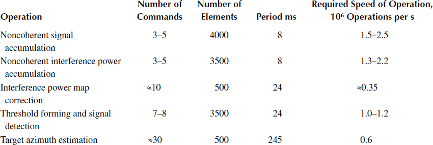
As follows from Table 9.1, the required effective speed of operation of the noncoherent target return signal preprocessing microprocessor subsystem under realization of the partial generalized signal processing algorithms is not more than 2.5 × 10⁶ operations per second. If we assume that all operations of the considered signal processing algorithm are executed by a single microprocessor, then the required speed of operations must be defined as
where is the total number of commands performed per as shown in Table 9.1, for the minimum number of commands required for a single realization of the considered generalized signal processing algorithm:
For calculating we considered that the noncoherent accumulation of the target return signals and interference and noise are realized twice, only within the limits of the cycle . Using (9.13) we obtain
Thus, as we can see, the requirement for speed of operation of the noncoherent target return signal preprocessing microprocessor subsystem is certainly high. However, the noncoherent target return signal preprocessing operations can be paralleled on two microprocessor subsystems. For example, the first microprocessor subsystem must perform the noncoherent accumulation of target return signals, corrections in the interference and noise power map, and the target azimuth estimation. The second microprocessor subsystem must carry out the noncoherent accumulation of interference and noise power, threshold forming, and signal detection. In this case, the required speed of operation for each microprocessor subsystem is not more than 2 × 10³ operations per s.
Now, let us estimate the requirements to the microprocessor subsystem memory capacity. Elementary considerations give us the following values of required memory capacity or the number of cells:
To store signal amplitudes—4000
To store intermediate results of noncoherent accumulation—4000
To store the estimations of interference and noise power—4000
To store the intermediate results of noncoherent accumulation of interference and noise power estimations—4000
To store the output signals of three azimuth directions—1500
To store the interference and noise power map—500 × 144 = 72,000
The total memory capacity is QΣ = 89,500.
9.5 Signal Reprocessing Microprocessor Subsystem Specifications
The information about the detected target pip coordinates comes in at the input of digital signal reprocessing subsystem (see Figure 9.4). The main tasks of digital signal reprocessing subsystem are to achieve the target trajectory detection, target tracking and target trajectory tracking, filtering of target trajectory parameters, and other digital signal processing algorithms derived during the target processing stages and to provide definite information to the user. In the said example, we assume that all tasks of the digital signal reprocessing subsystem are carried out by a single microprocessor subsystem. We also assume that the typical digital signal processing algorithms, which we discussed previously, modified for the case of two-coordinate surveillance radar are realized in the course of digital signal reprocessing. For this reason, we do not present in this section a detailed description of operations and global digital signal reprocessing algorithm. Some specific features of these digital signal processing algorithms are defined by specific application of the considered two-coordinate surveillance radar and are reduced to the following ones.
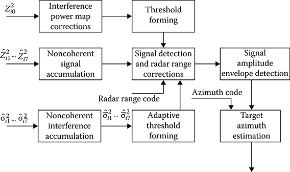
FIGURE 9.4 Complex algorithm of the noncoherent target return signal reprocessing.
To reduce the required number of operations for solving the problem of new target pip binding to target tracked trajectories, there is a need to perform a target trajectory picking within the limits of ±15° from a direction corresponding to the azimuth of new target pip. This rough narrow-beam pulse sampling by azimuth allows us to select only such target trajectories for comparison that can be continued using a new target pip taking into consideration their displacements in radial direction with maximum velocity and the acceptable number (three) of missing target pips on the target trajectory. Coordinate extrapolation at the instant of getting a new target pip, gating, and a verification of new target pip present within the limits of gate are carried out sequentially for the target trajectories thus selected. Gate dimension depends on the number of confirmation omissions that the target trajectory was tested in the previous scanning periods.
The target trajectory binding is carried out using the criterion “2 from 3”. The target trajectory binding can be also considered as a decision about the target trajectory detection. Thus, in the considered case, the operations of confirmation about the target trajectory bindings using one or several target pips are excluded.
Each detected target is estimated by the principle “important-not important,” and a decision “to apply-not apply” a signal processing to the detected target is made.
The information generated must be precise for it allows us to implement an individual smoothing of the Cartesian coordinates X and Y without taking into consideration the correlation between them. In this case, laborious operations on the vector and matrices are excluded while computing, which essentially reduces the number of operations under realization of the digital signal reprocessing algorithms.
Determination of the target velocity scalar of vector and the target course at nth step of filtering the Cartesian coordinates X and Y is made by the following formulas:
where and are the estimations of target velocity by the Cartesian coordinates X and Y. Logical flowchart of the digital signal reprocessing algorithm is shown in Figure 9.5. Based on this flowchart, the sequence and interaction of operations under realization of the digital signal reprocessing algorithm can be defined.
Now, consider the main requirements for the speed of operation and the memory capacity of digital signal reprocessing microprocessor subsystem. In the case of a single realization of the digital signal reprocessing algorithm partly responsible for processing a single new target pip, a reduced number of approximately 2 × 10³ operations are required. Considering that for each scanning period about 20 new true and 5 false target pips come in at the digital signal reprocessing microprocessor subsystem input, we obtain operations per scanning period. The scanning period is Tscan = 4.5 s. The required effective speed of operation is operations per second. Thus, we can conclude that the speed expected of the digital signal reprocessing microprocessor subsystem is not high.
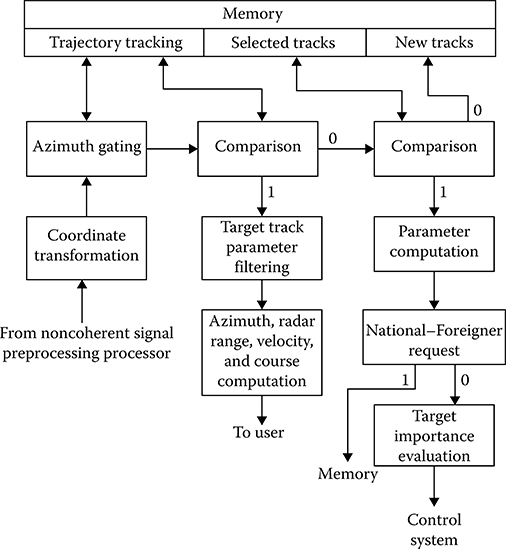
FIGURE 9.5 Digital signal reprocessing algorithm flowchart.
To determine the required memory capacity of digital signal reprocessing microprocessor subsystem, we assume that 10 false target pips are stored by the memory device in addition to the 20 true target pips. Our estimation shows that data about a single target trajectory requires approximately fifteen 32-bit words. Consequently, to store data about 30 tracked trajectories approximately four hundred and ffty 32-bit cells are required. Moreover, to store data on the detected target trajectories and the new target trajectories taking into consideration a reserved memory capacity, it is reasonable to have approximately 100 more 32-bit cells. The memory capacity requires about 400-500 cells. Thus, to solve the digital signal reprocessing problems we need about 103 memory cells.
The foregoing analysis shows the digital signal reprocessing problems do not require high computational resources compared to the previous stages of target return signal processing. This allows to assign for the digital signal reprocessing microprocessor subsystem the problems to control over all elements and parameters of the CRS and the problems of the current hardware and computational process control, additionally. Considering that the control optimization problems are not solved in dynamic mode in the automatic “radar complex-global digital signal processing complex” system and the control system is constructed as the system with a predetermined fixed sequence of control commands, we do not consider such system in the present chapter. It is assumed that the scheduled problems are considered and analyzed at the next stage of designing and construction of the CRS.
9.6 Structure of Digital Signal Processing Subsystem
Functional requirements, cost, reliability, conveniences in fault lookup, maintainability—all these factors are taken into consideration in the course of designing the global digital signal processing structure of the CRS. The functional requirements to individual elements of this structure, which have been discussed in the previous sections, are evidences of differences in the intensity of information flows processed by the central computer system of the radar complex. The digital coherent target return preprocessing subsystem working in real time has the greatest service load. For this reason, given the latest technological breakthroughs in signal detection and signal processing theory and in computer applications, there is a need to design and construct a specific nonprogrammable microprocessor subsystem for the digital coherent target return preprocessing subsystem working in real time, which consists of specific adders, mixers, convolution networks, memory devices based on VLSI, and charge injection devices. Without any doubts, we can state that the possibility of designing and constructing such specific microprocessor subsystems is the foundation stone to developing solutions for the problems encountered in automatic digital target return signal processing under real conditions of CRS functioning.
At the output of digital coherent target return preprocessing microprocessor subsystem the information density is essentially reduced, and at the stage of noncoherent digital signal preprocessing, we can use the programmable microprocessor subsystems. Analysis of requirements to specific subsystems of global computer system of radar complex and existing general avenues applicable to the microprocessor subsystems in digital target return signal processing systems favor using a module structure of target return signal processing systems, the main body of which consists of several identical microprocessor networks. Such microprocessor networks enhance ease of use, reliability, and effectiveness of the digital signal processing system as a whole. However, such microprocessor networks require that the problems of some stages of target return signal processing be parallel. In particular, we have considered such requirement while discussing the noncoherent target return signal preprocessing subsystem. Moreover, there is a need to focus on organizing the control process in such multimicroprocessor network system.
In our case, the control process must be hard; that is, it must be carried out in accordance with a program assigned before and must be subject to the given time sequence. This can be organized by way of instructions to carry out the signal processing and control problems using the specific stack memory with subsequent task choice in accordance with the time diagram of global digital signal processing system. After fulfillment of the immediate task, each micro-processor subsystem can select from the programmable control device memory the next task, indicating the following:
The operation that must be done
Initial data that must be used
Memory cells that should store the obtained results
Way for further computational process
Thus, carrying out the foregoing steps will enable the microprocessor networks to operate independently of each other. Increasing the number of microprocessor networks will enhance the reliability and speed of data processing without any changes in administration principles.
In accordance with general principles discussed thus far and needing consideration during the design and construction of the central computer system for global signal processing and control employed by radar complex, one variant of a structural flowchart is shown in Figure 9.6. These are the following subsystem boxes:
Coherent signal preprocessing microprocessor subsystem with the buffer memory to store the information data issued for the noncoherent signal preprocessing subsystem
Programmable control subsystem to control the CRS issuing the time sequence of control command and operations, such as
Radar antenna scanning control
Changing the transmitter carrier frequency
Computation of detection thresholds
Definition of operation mode—scanning mode or request “native–foreigner” mode
Radar synchronizer forming the signals controlling the global digital signal processing system and radar complex
Memory device to store the power map of interference formed by the underlying surface and local objects; this memory device is represented by individual box owing to large capacity and specific problems solved
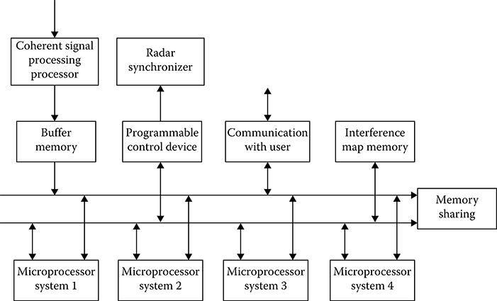
FIGURE 9.6 Structure of the central computer system for global signal processing and control.
Module of communication with the user, with interface functions “input-output,” preparation of information for display, and sending information by the communication channel
Four central microprocessor networks (three microprocessor networks are working and one microprocessor network is reserve) assigned to solve all problems and tasks of global signal processing and control system, except for the problems and tasks assigned for the coherent target return signal preprocessing subsystem
Memory device for cooperative use assigned for the execution of central computer system functions during data processing and control distributed in space and time
The structure of the central computer system for global signal processing and control employed by the radar complex gives us an original approximation under solution of the assigned problem. Furthermore, we need to consider all partial signal processing and control algorithms in detail, incorporate these algorithms into the complex signal processing and control algorithm, and design the functional time diagram of the system. This stage of designing must be started after selecting specific types of microprocessor networks and the decision whether it is practicable to continue with a specific process of CRS design and construction
9.7 Summary and Discussion
The first stage of system design of any radar system is the selection of structure and energy parameters of radar being a constituent of the CRS. The radar antenna type, shape, and width of radar antenna directional diagram, method and period of scanning coverage, transmitter power, duration and scanning signal modulation technique, period of scanning pulsing, resources and methods of protection from active interferences, and other radar parameters must be defined and justifed at this stage. At the second stage of CRS design the structure is designed, the parameters of digital signal processing subsystem are justifed, and the ways of specific realizations are defined. At the initial stages, the main problems and tasks of digital signal processing and control subsystem should be discussed and the procedures to solve these problems should be defined.
It is worthwhile to employ the rejector filters with the interperiod subtraction of the order ν and the filters of coherent accumulation in the form of FFT processors or filters in series to ensure the required quality of passive interference cancellation and to improve the detection performance of moving targets. Stabilization of the probability of false alarm is also a very important problem. The methods of adaptive threshold control under signal detection are widely used to solve this problem. The implementation of adaptation to the interference and noise power can stabilize the probability of false alarm under detection of target return signals, but, in this case, the average number of false detections is not controlled and can be estimated only during simulation and digital signal processing and control subsystem sample debugging.
Functions such as automatic target lock-in, target trajectory tracking, and target trajectory reset play a vital role and require thorough understanding. A demand to operate in automatic mode under conditions of the high-level interference requires sufficiently effective measures that prevent overloading of the digital signal reprocessing subsystem while processing both the targets that are not captured by the CRS and the false targets. These effective measures are as follows: effective algorithm to detect the target trajectories providing the methods and procedures to decrease the probability of false target track beginning; selection of target pips in target tracking gates taking into consideration the high density of false target pips; filtering the target trajectory parameters providing tracking of both the nonmaneuvering targets and maneuvering targets; implementation of specific algorithms of target classification providing a selection of the most important targets for target tracking; ensuring appropriate speed of operation and memory capacity of central computer system. Under the automatic mode of operation, the most important problem associated with the central microprocessor system is effective control of the CRS as a whole and functional synchronization of operations of all elements. Algorithmic designing and realization of digital signal processing and control subsystem are other problems to be considered while designing the central computer system.
The principle of division of signal processing procedure into various stages, that is, coherent digital signal preprocessing, noncoherent digital signal preprocessing, and digital signal reprocessing, forms the basis of designing the structure of global digital signal processing and control system of radar complex, which consists of the digital coherent target return signal preprocessing subsystem, digital noncoherent target return signal preprocessing subsystem, digital signal reprocessing subsystem, and digital control subsystem.
The digital coherent signal preprocessing subsystem ensures an interface between the analog receiver linear tract and the central computer system of radar complex. The following important operations are carried out by the digital coherent signal preprocessing subsystem: analog-to-digital conversion; generalized signal processing algorithm of linear-frequency-modulated target return signals; suppression of passive interferences; coherent accumulation of target return signals; and generation of data to solve the problems related to stabilization of the probability of false alarm. The digital coherent signal preprocessing subsystem is realized by individual microprocessor sub-subsystem or distributed set of specific microprocessor subsystems. Choosing the right approach to design and construct the digital coherent signal preprocessing subsystem and justification of structure of the corresponding microprocessor sub-subsystem or set of microprocessor sub-subsystems is the first and foremost requirement of the system design process.
It is worthwhile to employ hardware in the specific digital coherent signal preprocessing sub-system designed based on VLSI microprocessor sub-subsystem to solve the following problems: generalized signal processing algorithm, suppression of passive interferences, computation of target return signal amplitudes, and estimation of interference and noise power. To solve the problems of Doppler filtering, it is worthwhile to implement the FFT processor or filter using effective and simple methods and procedures such as complex multiplication. All elements of the specific digital coherent signal preprocessing subsystem designed based on VLSI microprocessor sub-subsystem must possess high reliability and require low power consumption. High reliability can be achieved by equipment reservation or information redundancy. Low power consumption can be achieved by very careful circuit designing and implementation of VLSI with small power dissipation.
The first element of the global structure of digital coherent target return signal preprocessing sub-system is the ADC of the target return signals at the phase detector output. Next element of the total structure of the digital coherent target return signal preprocessing subsystem is the DGD for linear-frequency-modulated target return signals that can be realized in the time domain employing the nonre-cursive filter or in the frequency domain using the FFT processor or filter. To improve the DGD speed of operation, we can use properties of parallelism applied to the matched filtering algorithms. For this reason, to realize the DGD with high speed of operation we can use the parallel mixers based on ROM, parallel adders with simultaneous addition of several numbers, and parallel registers. The nonrecursive smoothing filter with short impulse response is placed after DGD. The main tasks of this filter include the following:first, suppressing the signal side lobes at the DGD output and, second, decreasing the sampling rate to frequency corresponding to requirements of the sampling theorem. A decrease in the sampling rate in m times (m is the integer) is carried out by the element providing a sample of each mth element from sequence of input sampled target return signals.{x (kTs)}. The cancellation of correlated interference is realized after the matched filtering. The operations discussed are part of the first stage of the digital coherent signal processing. To ensure the required reliability all hardware elements of the first stage must be doubled. The output signals of the main and reserved hardware set are compared by specific modules. Comparison results are used by both the searching system and the default system.
In accordance with the global structure of digital signal processing and control system used by the radar complex (see Figure 9.1), the noncoherent signal preprocessing subsystem solves the following problems: (a) noncoherent accumulation of signals after the coherent signal processing of each from three 8-pulse bursts by the FFT processor or filter; (b) noncoherent accumulation of interference and noise power estimations for all Doppler channels, except for the zero Doppler channel, and for all resolution elements by radar range; (c) corrections of the interference and noise power map, forming the adaptive detection thresholds; (d) signal detection to be provided by comparison between the signals and the corresponding thresholds computed for each cell’s “radar range–Doppler frequency”; (e) estimation of the target azimuth by a set of signals exceeding the detection threshold at three neighboring positions of the radar antenna directional diagram by azimuth.
The requirements to speed of operation of the noncoherent target return signal preprocessing microprocessor subsystem are sufficiently high. However, the noncoherent target return signal preprocessing operations can be conducted in parallel using two microprocessor subsystems simultaneously. For example, the first microprocessor subsystem must perform the noncoherent accumulation of target return signals, corrections in the interference and noise power map, and the target azimuth estimation. The second microprocessor subsystem must carry out the noncoherent accumulation of interference and noise power, threshold forming, and signal detection. In this case, the required speed of operation of each microprocessor subsystem is not more than 2 × 10³ operations per second.
The main tasks of the digital signal reprocessing subsystem include the following: to realize the target trajectory detection, the target tracking and target trajectory tracking, the filtering of target trajectory parameters, and other digital signal processing algorithms accomplished during the target processing stages, and to provide precise information to the user. The analysis performed thus shows that the digital signal reprocessing problems do not require the high computational resources in comparison with the previous stages of target return signal processing. This fact allows us to assign for the digital signal reprocessing microprocessor subsystem the problems of control over all elements and parameters of the CRS and the current hardware and computational process control problems. Taking into consideration that the control optimization problems are not solved in dynamic mode in the automatic. “radar complex–global digital signal processing complex” system and the control system is constructed as the system with a fixed, predetermined sequence of control commands.
Functional requirements, cost, reliability, conveniences in fault lookup, maintainability are the important factors that are taken into consideration in the course of designing the global digital signal processing structure of the CRS. The functional requirements to individual elements of this structure discussed and considered previously are evidences of differences in the density of information flow processed by the central computer system of radar complex. The digital coherent target return preprocessing subsystem working in real time has the greatest service load. For this reason, and given the technological breakthroughs in the signal detection and signal processing theory and computer applications, there is a need to design and construct a specific nonprogrammable micro-processor subsystem for the digital coherent target return preprocessing subsystem working in real time, which consists of the specific adders, mixers, convolution networks, memory devices based on. VLSI and charge-injection devices. Without any doubts, we can state that the possibility of designing and constructing such specific microprocessor subsystems is the foundation stone for developing processes that solve the problems encountered in automatic digital target return signal processing in the functioning of the CRS under real-time conditions.
References
1. Moon, T.K. and W.C. Stirling. 2000. Mathematical Methods and Algorithms for Signal Processing. Upper Saddle River, NJ: Prentice Hall, Inc.
2. Billingsley, L.B. 2002. Low-Angle Radar Land Clutter—Measurements and Empirical Models. Norwich, NY: William Andrew Publishing, Inc.
3. Richards, M.A. 2005. Fundamentals of Radar Signal Processing. New York: McGraw Hill, Inc.
4. Levy, B.C. 2008. Principles of Signal Detection and Parameter Estimation. New York: Springer Science + Business Media, LLC.