
Chapter 3
Introduction to the Surface Editor
Just as a quick note before we delve into the mysteries of the Surface Editor, I want to point out that in order to set up surfaces for your objects, you will need to have assigned appropriate surfaces to your model in Modeler. This may seem a pretty obvious thing to do, but I want to ensure that I mention every step of the process, and assigning surfaces to the model is naturally the first step. And because a lot of surface creation is best done within Layout, remembering to assign surfaces may have slipped your mind!
To assign a surface to an object in Modeler, simply select the polygons that you want to apply the surface to and press “q.” The Change Surface dialog pops up with a number of basic options, including a space to enter the name of the surface. Set these up as you wish, bearing in mind that you can change these settings later.

Figure 3-1
Opening the Surface Editor
Once you have all your various surfaces assigned to your object, you are ready to begin using the Surface Editor, which is the place where you assemble all your textures and create all your surfaces.
To open the Surface Editor, you can press Ctrl+F3, the default keyboard shortcut, or press the Surface Editor button just below the top of your toolbar.
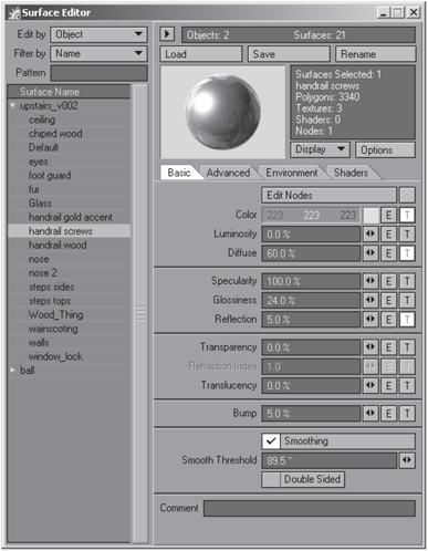
Figure 3-2: LightWave’s Surface Editor panel
Notice that any objects you currently have open or that are within your scene are listed on the left side in the Surface Name list. This list displays every surface assigned to each different object file. You can collapse this list by clicking the arrow button above the Load button on the right side of the panel. If you do this, a drop-down list labeled Surface appears, from which you can select the surface you wish to work on. For ease of use, let’s just keep the panel the way it is for now. You can click on the little white triangle next to each object name in the Surface Name list to expand and display all the surfaces assigned to that particular object.
Edit Modes
At the top-left corner of the Surface Editor is the Edit by button. There are two edit modes available for the Surface Editor: Object and Scene.
The Object editing mode is a “discrete” editing mode, in that it allows you to work on each surface individually, regardless of whether there are multiple surfaces that share the same name in the scene. This pertains particularly to when you are working in Layout with a number of different objects, some of which have surfaces with the same names. Using the Object editing mode will ensure that each surface is treated individually and that no global changes are accidentally made. Object is the default editing mode.
Whereas Object edit mode allows you to keep surfaces completely separate, Scene edit mode applies changes globally. This means that if you are working with a number of different objects in your scene, the scene editor condenses all the surfaces that share names and treats them as single surfaces. In other words, if you have two different objects, each of which has a surface named “black plastic,” selecting the surface and making changes to it will affect both surfaces with that name. This is particularly useful when you have a lot of objects that you want to share surfaces, and eliminates the hassle of copying and pasting surfaces from file to file. When using Scene edit mode, notice that the list of surfaces in the Surface Editor is much shorter and does not list the surfaces according to the object they are on.
NOTE: The edit mode that you use is saved from session to session. Consequently, if you are using Scene mode, when you load up your scene again, LightWave will apply the settings of the last object loaded to the others sharing that surface name.
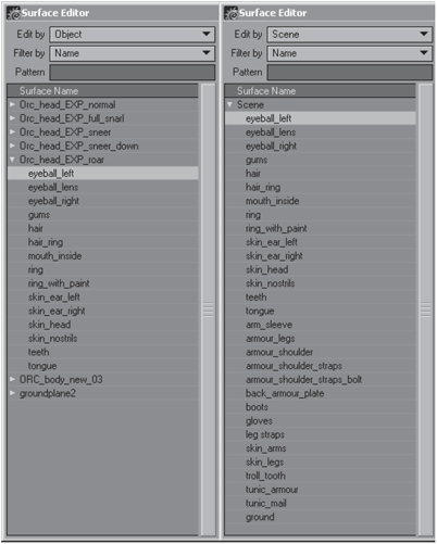
Figure 3-3: Object edit mode (left) and Scene edit mode (right). Notice the way in which Scene edit mode condenses all surfaces with the same name to a single surface.
Filtering Options
Below the Edit by button you will see the Filter by button, which basically allows you to control what surfaces are shown in the Surface Editor. By default, the Name option is active. This option shows all the surfaces within the scene (in Layout) or on the object (in Modeler) in alphabetical order.
The next filter option is Texture. Selecting this will display only surfaces that use procedural textures.
Similarly, the Shaders option displays only surfaces that use shaders.
The Preview option will display all surfaces that are currently included within the image in the render buffer, on a pixel-by-pixel basis. Of course this means that you will have to render a frame first, and naturally, this option can only be used in Layout.
Below the Filter by button is the Pattern field. This is simply an extension of the Filter by button. Entering any text that appears in any surface name into the Pattern field will display those surfaces in the Surface Editor. For example, if you have a few surfaces that have names that include the word “skin,” you can type the word into the Pattern field and the Surface Editor will only display surfaces containing the word “skin.”
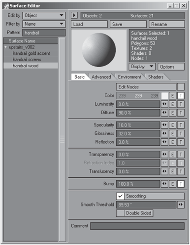
Figure 3-4: Using the Pattern field to filter surfaces displayed in the Surface Editor
Loading, Saving, and Renaming Surfaces
On the top-right side of the Surface Editor we find a few basic file options, namely Load, Save, and Rename. The Save option allows you to save the surface you have currently selected to an external surface file (.srf file), while the Load function simply loads a surface (.srf) file into the currently selected surface. The Rename option allows to rename your surfaces.
NOTE: You can also right-click on any surface name, which gives you options for copying and pasting entire surfaces from one to another.
The Preview Window
Directly below your file and surface name options is the preview window. This little window gives you an idea of what your current surface looks like.
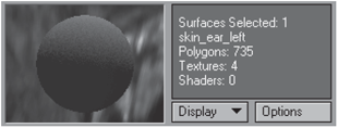
Figure 3-5: The preview window
Clicking the Options button gives you a few customizable options for how the preview window displays your previews (see Figure 3-6).
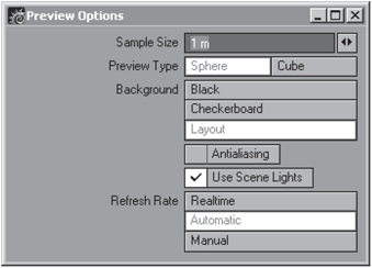
Figure 3-6: The Preview Options panel
The Sample Size option allows you to set the surface area size of the little sphere shown within the preview window. Ideally, one should set the sample size close to the actual physical size of the area to which the surface is applied; however, it is also useful to check very tiny details you may be adding to your surface by changing this value to a rather small one. Preview Type allows you to change your preview object to a sphere or a cube.
NOTE: Unfortunately, if you are working with UV maps, this preview window cannot display them, no matter what you set these options to.
Background gives you a couple of options to choose for the backdrop behind the preview sample. Black is obviously plain, flat black. Checkerboard gives you a backdrop of little black and white checks. This option is particularly useful for checking transparency and refraction settings. Layout displays the backdrop settings that you have created for your scene in the Background settings panel found under Layout’s Effects panel. This setting is only available in Layout.
Antialiasing activates or deactivates antialising in the preview window. Antialiasing gives you a smoother sample, but takes slightly longer to update within the window.
Activating the Use Scene Lights option uses the lighting setup in your scene instead of the default lighting to illuminate the sample in the preview window. This can be useful in determining how your color and other surface settings will react to your current lighting. This setting is also only available in Layout.
Refresh Rate sets the manner in which the preview window updates itself. Realtime updates the sample whenever you make any adjustments to interactive controls, such as adding texture layers or adjusting values. Automatic updates whenever you release your mouse button after making any changes or selecting a new surface. Manual updates only when the preview window is clicked. This last option is useful when you are working on complex scenes that are hogging your system memory.
To the left of the Options button is a button labeled Display. If you wish to concentrate on a particular surface channel, you can set your preview window to display only that channel by selecting it from the Display list. Render Output is the default setting, and displays the surface as it would appear when rendered.
TIP: All of these options can also be quickly accessed by right-clicking on the preview window itself.
Edit Nodes
The first option under the Basic tab in the Surface Editor is a button called Edit Nodes along with a check box. This little button opens up a whole new world for texturing in LightWave. Node networks have been the norm in high-end 3D packages for a very good reason — flexibility. Now don’t let this intimidate you; node texturing will be your best friend once you understand some things before you dive into creating shading networks. We discuss the Node Editor further in Chapter 14, “The Node Editor.”
Smoothing
Leaving the actual surface attributes themselves for the time being, we now look to the bottom of the Basic tab on the Surface Editor panel, where we find the Smoothing option.
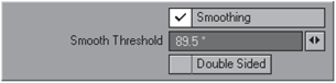
Figure 3-7: The Smoothing option
Smoothing is a method that LightWave uses to create the effect of smooth surfaces when they are, in fact, made of loads of flat-faced polygons. If smoothing is not on, the polygons that make up your object are clearly visible. This is usually not the effect that you want, since it would result in your rendered model looking jagged (pixelated) and blocky across its surface. So LightWave uses a shading model called Phong shading to create the illusion of the model being smooth by taking the points where smoothed polygons meet and making them appear as if they are one continuous surface as opposed to separate polygons.
You can activate Smoothing by checking the little option box.
Smooth Threshold determines the angle limit at which LightWave ceases to smooth. If the angle between two joined polygons is equal to or greater than 90°, as it would be in the case of a shape such as a cube, LightWave will not, by default, create any smoothing, unless you adjust the Smooth Threshold setting. The default Smooth Threshold amount is 89.5°, which means that anything over that amount will not be smoothed unless you specify that it should be by changing this amount.
It is important, however, to note that smoothing does not affect the actual geometry of an object. Although the object may appear smooth when rendered, sometimes you may still be able to discern the individual polygons along the model’s edge, especially when viewed up close. If you find this happening with your models, you will need to smooth your actual model by adding more geometry.
Double Sided Surfaces
Below the Smoothing and Smooth Threshold options is the Double Sided option. You can activate it simply by checking the little box. Double Sided makes your polygons appear to be two-sided, which can be useful should you need to go inside the object or if you are working with an object that is very thin, such as a piece of paper or fabric, that has been modeled with only one-sided polygons.
Double Sided is also very useful for making glass surfaces or transparent plastics appear to have more thickness. These surfaces are explored in greater detail later in this book.
Be aware that using the Double Sided option does result in longer render times, since LightWave has more polygons to render.
The Comment Field
Below the Double Sided check box is the Comment field.
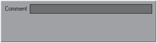
Figure 3-8: The Comment field
You can enter notes or comments into this field if necessary. This is rather useful for leaving notes to any other texture artist who may have to work with surfaces that you have set up or for keeping track of changes that you have made in the particular surface.