
Analogue theory
In telecommunications, the resource of electromagnetic spectrum – which is the basis of telecommunications – is commonly referred to as RF – an acronym for radio frequency. In our context, it does not refer to media such as radio stations and their broadcasts, but refers to the term used in the scientific sense, as defined in the dictionary, as ‘rays’ or ‘radiation’.
This can be confusing for non-scientists, but is in fact the original definition of radio. It has also been historically referred to as ‘airwaves’, or as the ‘ether’, and a specific frequency in the spectrum can be referred to as a ‘wavelength’. All these terms refer to electromagnetic spectrum.
Many of you will have heard of technologies associated with the word digital, and perhaps also heard reference to the word ‘analogue’ (usually associated mistakenly with old-fashioned) – but what do they mean?
Analogue basics
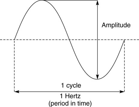
All forms of electromagnetic radiation (including light) can be thought of as consisting of waves. In electronics, an analogue signal is a wave signal that carries information by the continuous varying of its amplitude (size) and frequency (period) as shown in the diagram.
The concept is comparable to two people, each holding the end of a rope and standing some distance apart.
One person acts as the ‘transmitter’ and one as the ‘receiver’. The ‘transmitter’ flicks the end of the rope up and down, creating a wave shape that passes down the rope to the ‘receiver’.
The harder the rope is flicked, the greater the amplitude of the wave, and the more frequently it is flicked, the faster the waves are created and the faster the rope oscillates.
This demonstrates the two fundamental properties of an analogue signal – amplitude and frequency. One complete wave is equal to 1 cycle or 1 Hertz (Hz).
Analogue wave cycle
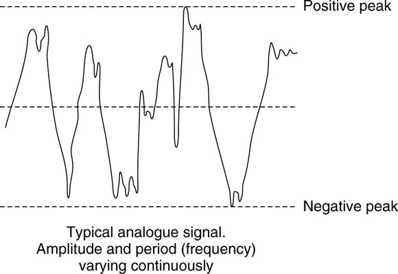
This is how many electrical signals are conveyed, such as those reproduced by hi-fi systems. In terms of audio, the amplitude is the volume or ‘loudness’, and the period is the frequency or ‘pitch’ of the audio signal.
The human ear is sensitive to a frequency range of approximately 5020 000 Hz (20 kHz), and so, loud, high-pitched sound signals correspond to large and closely spaced waves, and quiet low-pitched signals to small and widely spaced waves.
Obviously, these elements vary independently to create the spectrum of the typical audio programme sound.
Frequency and wavelength
When we talk of the frequencies used for transmitting video and audio, we refer to signals as radio frequencies (RF), but this is not strictly limited to the relatively narrow band of frequencies that we listen to radio broadcasts on. It also refers to a very wide range of frequencies that encompass microwaves as well.
Historically, frequencies were measured in terms of the distance (in metres) between the peaks of two consecutive cycles of a radio wave – wavelength – instead of the number of cycles per second or Hertz.
Even though radio waves are at a very high frequency, there is a tiny (but measurable) distance between the cycles of electromagnetic waves. This corresponds to the distance light would travel, as electromagnetic waves travel at the speed of light – 300 000 km per second.
As we characterize electromagnetic waves by their wavelength, radio waves have much shorter wavelengths and therefore higher frequencies than audio signals.
| Order of magnitude | Notation | |
| 1 | 1 Hz | |
| 100 | 100 Hz (0.1 kHz) | |
| 1000 | thousand – kilo | 1 kHz |
| 1 000 000 | million – mega | 1 MHz |
| 1 000 000 000 | thousand million – giga | 1 GHz |
But comparing with further up the electromagnetic spectrum, radio waves have much longer wavelengths and thus lower frequencies than visible light waves.
However, when sending video and audio via a radio signal, just transmitting pure wave signals is not enough if we want to convey such complex information as pictures and sound. We need to superimpose the information onto the pure wave signal, using a process called ‘modulation’ – we will look at this further in a while.
Phase
An electromagnetic wave signal also possesses the property of ‘phase’, and a complete cycle can be said to equal to 360° (as in a circle). Looking at our wave signal from just now, let us compare it with an identical signal alongside it.
Phase comparison
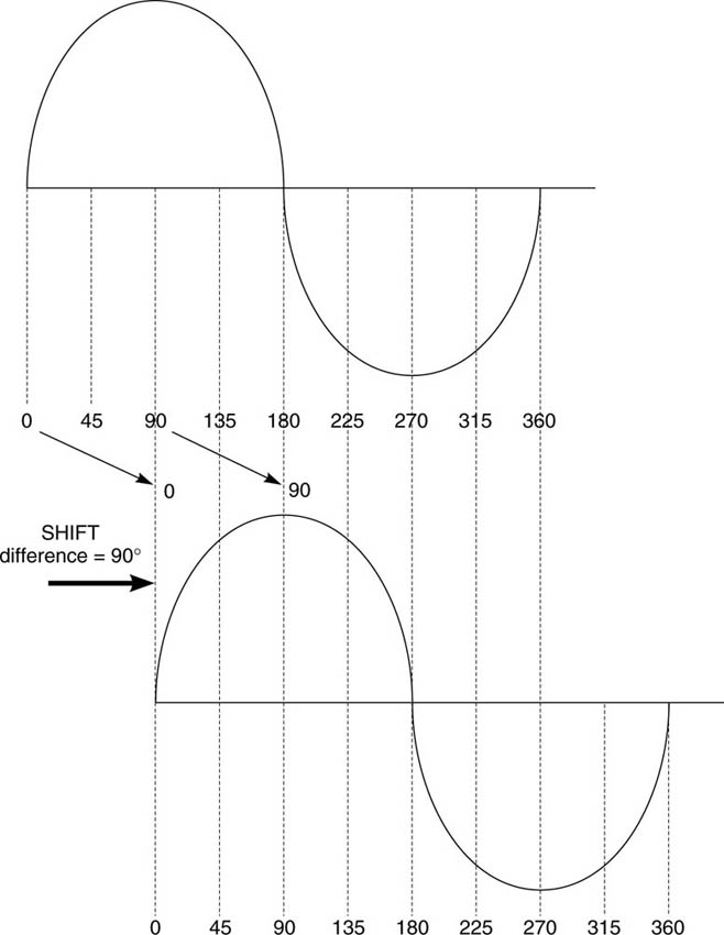
If the two signals are exactly coincident, i.e. the peaks and troughs occur at exactly the same time, they are said to be ‘in phase’. If there is a difference (as shown in the lower part of the diagram), then there is a phase difference and the signals are said to be ‘out of phase’ relative to each other.
A practical example of the out-of-phase condition is when you wire the speakers up on your hi-fi, but reversing one speaker’s positive and negative connections. When you feed music via the amplifier to the speakers, then as one speaker cone moves in and out reproducing the music, the other speaker cone is moving in the opposing direction, counteracting the sound pressure waves from the other speaker. The result is that the sound waves in the room tend to almost cancel out, and you end up with a rather thin reedy sound. There is no damage done to the speakers (unless you turn them up really loud!) but the phase cancellation will completely spoil the music.
The property of phase is important in microwave and satellite communications, and particularly when we look at some types of modulation.
Modulation principles
Our video or audio signal is a message or information signal. A radio transmitter is a device that converts this type of message signal (often termed the baseband signal), to a signal at a much higher frequency and power that can travel over a distance (often termed the carrier signal). Although it is at a much higher frequency, the amplitude and the frequency of the original signal can be received at a distant point. The process of preparing this transmitted signal, which is a mixture of the information and a carrier signal, is called ‘modulation’. The opposite process of recreating the original baseband information signal is called ‘demodulation’.
There are a number of different types of modulation, but analogue modulation techniques generally fall under either amplitude modulation (AM) or frequency modulation (FM).
AM
Amplitude modulation is a process where a baseband message signal modulates (alters) the amplitude and frequency of a high frequency carrier signal that is at a nominally fixed frequency, so that the carrier signal varies in amplitude and frequency in concert with the baseband signal. The intensity, or amplitude, of the carrier wave varies in accordance with the modulating signal, and a fraction of the power is converted to ‘sidebands’ extending above and below the carrier frequency.
If this signal is analysed, it can be seen to contain the original carrier signal plus these lower and upper sidebands of frequencies. The entire modulated carrier now occupies a frequency range termed the RF bandwidth. However, this form of modulation is not an efficient way to send information, particularly for our purposes – we have just described it here for illustrative purposes so that you get the idea.
AM
FM
Frequency modulation is of more interest as it is used for analogue transmissions in particularly analogue terrestrial microwave. The principle of FM is based on a carrier wave signal that shifts up and down in frequency (deviates) from its centre (at rest) frequency, in direct relationship to the amplitude of the baseband signal, though the amplitude remains at a constant level.
FM
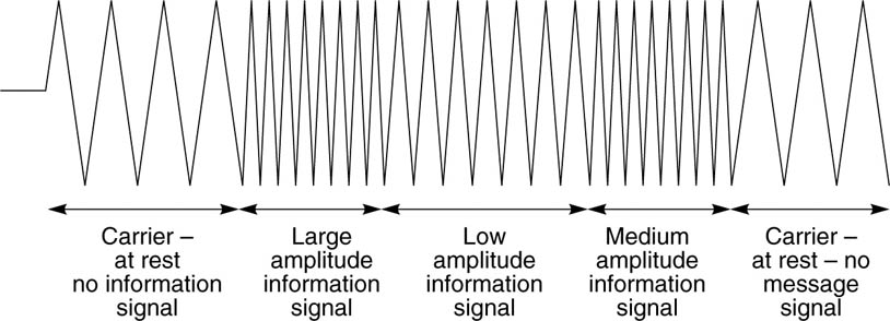
The maximum deviation (frequency shift) of the frequency is equal above and below the centre frequency, and is usually referred to as the peak-to-peak deviation.
In an FM signal, the instantaneous frequency of the baseband signal is represented by the instantaneous rate of change (speed of change) of the carrier frequency. If the modulated signal waveform is viewed on an electronic
measurement instrument such as an oscilloscope or a spectrum analyser, the relationship appears much more complex than in AM, and it is difficult to see exactly what is occurring.
The advantage of FM is that the signal has significantly greater protection from random effects (termed noise) than AM, and is much more effective than AM at very high carrier frequencies used for satellite transmissions. FM is spectrally very inefficient, i.e. the amount of bandwidth required to transmit a message signal is greater, but if the right conditions are met, it produces a much higher quality signal compared to AM. The concept of FM is quite a difficult one to grasp, but it is important to understand that for our purposes it is an efficient way of transmitting information.