Flyaways
Flyaway systems fulfil a primary requirement for a system that can be easily transported by air and reassembled at location in typically under an hour – a flyaway can even be rigged and operated out of the back of an ordinary box-body truck.
The flexibility of flyaways in ease of transportation is of critical value to international newsgatherers, who regularly fly all over the world with such systems in a variety of sizes and types of aircraft.
The key factors are total weight and number of cases, as news crews frequently transport these systems on scheduled commercial flights as excess baggage. Costs consequently increase greatly in direct proportion to weight and volume.
The design of a flyaway has diametrically opposed demands. Strength has to be achieved with minimum mass while also sustaining stability. Precision and adherence to close mechanical tolerances have to be met while all components have to be rugged.
Overall size has to be minimized while also achieving maximum uplink power. The individual component parts have to be in an easily assembled form for both minimum rigging time and reliable operation.
Either the antenna is transported in a single piece or it is broken down into a number of segments or petals. It can then be mechanically reassembled on-site onto the support or mount system, which has to be achieved to a very high tolerance.
The antenna has to be mounted so that it can easily be steered to align to the satellite correctly. Yet at the same time, the mount has to provide maximum rigidity and stability to maintain pointing accuracy up to the satellite during operation even in poor weather.
However, this physical rigidity has to be achieved while keeping the mass (and therefore weight) of both the mount and the antenna to the minimum. The use of carbon fibre and aluminium alloys is common to achieve these design aims.
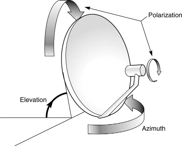
The control of the antenna is a very precise engineering requirement. The antenna has to be able to be finely adjusted in three axes – azimuth, elevation and polarization, as shown in the figure opposite.
Azimuth (the rotational position), elevation (the angle of tilt) and polarization (the circular orientation of the beam) all have to be controlled to within fractions of a degree.
There are typically both coarse and fine adjustment controls provided on the mount to achieve this.
The coarse controls allow rapid movement of the antenna to a point very close to the desired position, while the fine controls allow precise final alignment of the antenna towards the satellite.
When the antenna has been aligned, it is critically important that the antenna remains on-station, as once it is correctly positioned, it must be positively locked in position so that it cannot then be knocked off alignment accidentally or by bad weather.
Manufacturers use different techniques to achieve stability, based either around simple tripods, complex stabilizing frames and legs, or even interlocking the antenna and mount to equipment cases to increase the ground footprint of the system.
Azimuth, elevation and polarization
The antenna must also be capable of being positioned on uneven ground and retaining pointing accuracy under quite severe weather conditions such as high winds.
In aerodynamic terms, the antenna represents a sailplane, so it is important to bear in mind that there is a maximum survival wind speed as a measurement of stability in poor conditions.
Antennas
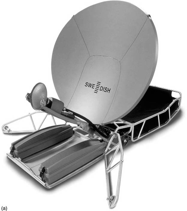
The antenna itself in a flyaway system is typically between 0.9 and 2.2 m, and as previously mentioned it is also usually segmented to allow easy transportation.
Only the smallest antennas (1 m or under) can easily be shipped as a single piece assembly. Antennas are usually either circular or diamond-shaped (or even a flattened diamond-shape) though the smaller antennas are typically circular, as shown in the following pages 115 and 116.
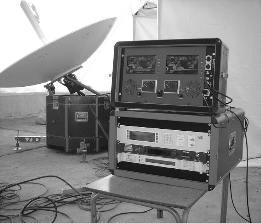
Flight-cases
The remainder of the system consists of a number of cases of electronic equipment where the equipment is grouped in a manner to keep the number of cases to a minimum but also allow easy manual handling.
Typically, the electronic equipment is fitted into flight-cases. This grouping also has to match the functionality of the system, so that the component parts that directly electrically interconnect are also next to each other, particularly for high-power RF signals.
1.5 m Flyaway antenna ((a) © SWE DISH Satellite Systems AB)
A flight-case is essentially a case that has an outer skin of (usually) metal while the contents are in some way protected against mechanical shock. This shock protection is high-density foam for the antenna and mount elements, and sprung-mounted frames for the electronics.
An equipment flight-case has an internal shockproof-mounted frame into which the electronics are fitted in such a way as to allow quick and easy set-up for operation at the destination. The removable front cover allows access to the front control panel, and typically has neoprene seals to protect ingress of water and dirt during transit.
The rear of the case may also be removable to allow access to rear panel connectors and controls. A flight-case typically costs several thousand dollars, and this may seem very high until the cost of the equipment it is designed to protect is taken into account – which can be typically ten times the cost of the case.
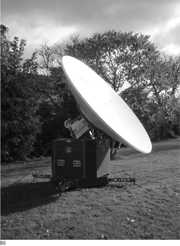
2.4 m Flyaway antenna ((b) © GigaSat Ltd)
The case also has to be able to allow the equipment inside to operate satisfactorily in extremes of temperature, high humidity, driving rain, or standing in shallow puddles.
Some cases are also designed to minimize the effects of any external electromagnetic interference (EMI). Taking into account all these factors, it is easy to see why the cases are so expensive.
Nonetheless, the fact that the cases are so rugged does not mean that the usual standards of care in handling delicate electronic equipment can be neglected.
If care is taken in handling as well as the use of these cases, the equipment should be fully operational when it reaches its destination.
The baseband equipment provided with an SNG uplink can vary widely, from simple monitoring of the incoming video to providing a small OB facility. This may include vision switcher, routing matrix, one or more equipped camera positions and comprehensive studio-remote communications.
Flight cased system (© GigaSat Ltd)