
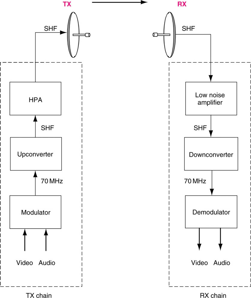
Transmission and reception chains
In an analogue microwave link, the baseband video and audio signal from the camera and the microphone is connected to the input of the modulator. This takes the basic message signal and modulates it, using the FM process, turning it into an RF signal called the intermediate frequency (IF) signal typically based on a 70 MHz carrier. The output of the modulator is fed to an upconverter, which shifts the frequency of the IF signal from the relatively low 70 MHz frequency up to the super high frequency (SHF) of the microwave transmitter – typically in the 2.5, 5 or 7GHz frequency bands. This is then amplified, fed to the antenna and transmitted as a microwave signal. The power of the transmit amplifier is typically between 5 and 15 Watt (W), where Watt is the measurement of power.
At this point we need to briefly mention decibels (dB). Often in signal processing we want to express ratios (particularly of power), and these can be clumsy to handle (remember working with fractions at school!). So engineers tend to talk in decibels. The convenience of using decibels is that multiplication and dividing of ratios can be performed by simply adding or subtracting values in dBs. The decibel is widely used in electronic engineering, and it is also a logarithmic unit – that is to say, 2 dB does not represent twice the power that 1 dB does (in fact, 3 dB is twice the power).
In our transmit amplifier, we have said it is typically between 5 and 15 W – and this corresponds to 7–11.75 dB in power. It is not necessary in this book to go into the maths, but you will see decibels cropping up from time to time.
The receiver consists of the mirror of this process. The received signal is picked up by the antenna, boosted by a low noise amplifier, downconverted from SHF to 70 MHz, and then demodulated to recover the original video and audio baseband signal. Each end of this process is called a transmission and reception chain respectively.
For a digital COFDM link, the video and audio is fed via an MPEG-2 digital compression encoder, which then feeds the modulator. At the receive end, the output of the demodulator is fed to an MPEG-2 decoder. Often these modulator/demodulator processes are included within the encoder/decoder units.
Audio channels
In an analogue microwave link the audio channels are not transmitted directly but are instead added as sub-carriers to the main carrier signal.
The audio signal from the microphone or VTR is fed into the microwave link modulator, which converts the incoming audio signal into an extra narrow FM carrier that is mixed with the main FM video carrier signal.
Each audio channel is thus added as a sub-carrier, and typically there are at least two audio sub-carriers on a terrestrial analogue link – because we need to either carry stereo, which is a two-channel system, or separate audio channels for the atmospheric natural sound (or effects) at the scene, and the voice commentary from the reporter (or track).
Basic TX and RX chains
For a digital COFDM link, the modulator is fed via an MPEG-2 digital compression encoder, and the output of demodulator is fed to an MPEG-2 digital decoder. Often these modulator/demodulator processes are included within the encoder/decoder units.
Why would we need to send the track and effects separately? Why not just send a single mix of the effects and the track together? Well, this helps in editing later, as having separate audio tracks allows the video editor the greatest flexibility when cutting different versions of the same story as it changes. It also allows different commentary track.
Handling of baseband audio – digital vs analogue
Audio is typically acquired and handled in analogue form, but it is possible that you may come across audio that has been converted into digital audio. We saw earlier how an analogue signal is converted to a digital one, and digital audio is commonly found in the broadcast studio environment.
The advantage of digital audio is that it is not affected by the transmission process (unless the transmission performance falls below a critical minimum level), and it can be embedded into a digital video stream and hence cannot get separated or misrouted. The disadvantage is that any manipulation of the audio – level, equalization (bass/treble boost/cut), etc. – is more difficult to carry out in the digital domain.
Hence it would be typical in ENG to make any changes to the audio while it is still in the analogue domain, and only digitize it (if required) at the point just before transmission. In general however, audio is handled as analogue in a ENG microwave link, except when digital microwave links are being used. Even then, as we have just noted, it is usual to carry out any production process while still as an analogue signal.
The audio that is fed to the link transmission chain is often fed via an audio mixer, as this gives the operator the opportunity of both making sure that the overall level is adequate, and also enable the mixing of sound from two sources – for example, a live ‘talk-in’ from the reporter with a live microphone to a piece of video pre-recorded and being played from the VTR in the truck. In an ENG truck, the audio mixer is often a small unit with 6–8 input channels, as opposed to the massive 32 or 48 input channel audio mixing desks found in large OB production trucks.
This is in essence the whole process. Obviously there is a good deal of sophisticated signal processing going on here, but so long as you understand this basic concept, you will be able to understand the setting up and use of microwave links.