
SNG operations – locating the uplink
The satellite uplink plainly has to be located where the story is, and the logistical and safety considerations involved as part of the decision of where to place the uplink are covered later. Hopefully it has become clear from our earlier discussions that both satellite uplinks and downlinks have to be accurately positioned and pointed at the satellite. For SNG uplinks, essentially transient in terms of their location, this is an important consideration in deciding where an uplink can be placed.
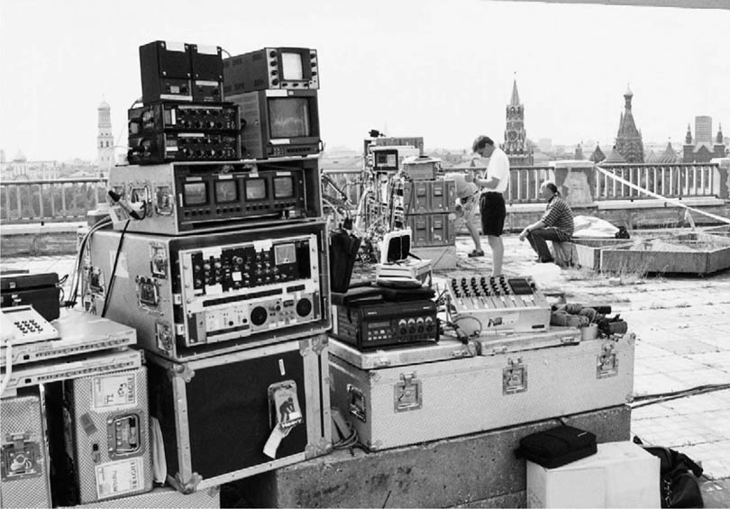
Rigging the uplink (Photo courtesy of Paul Szelers)
The uplink has to be stable, and therefore whether mounted on a vehicle or as flyaway, sitting on ground or a building roof, it must not be in a position where it could be knocked or blown off alignment.
Having found a stable position, the uplink has to be sited where it has a ‘look-angle’ that gives it a clear ‘get-away’ to the satellite. This means that it has to be sited so that there are no obstructions such as buildings, trees or passing high-sided vehicles that can block the transmission path to the satellite. In urban areas in particular, this can be quite difficult, as even a roof-mounted antenna on a truck can be obscured by a moderately tall building close by. It is of particular concern where the uplink may be located on streets running on an East–West parallel which may obstruct the path to a satellite to the North or South (depending on the hemisphere). If the satellite is on a particular low elevation angle (typically below 20°) this will increase difficulties in built-up areas.
Because of the range of types of uplinks available – both trucks and flyaways – it is not possible to give detailed instructions on how to set up and operate an uplink, and the uplink operator must rely on manufacturers’ training courses and instruction manuals.
One thing to note in particular with flyaway ‘rigs’ – they are rarely neat and tidy and cables run everywhere like a tangle of spaghetti. Rigging often takes place under time pressure, and there is rarely time to consider in very much depth the neatest way of doing things – rigs tend to grow from the middle out.
But the following gives a general explanation of the most difficult part of the operation – finding the bird (satellite)!
Finding your satellite
When you are aligning a satellite uplink you cannot just spray signals around as you search for the satellite – this is the fundamental difference between aligning satellite links and terrestrial satellite links. Before beginning to set up the uplink, the operator should have a table of the satellites that can be ‘seen’ from the location. This list must include the azimuth and elevation figures for each of the satellites, and particularly important is having the magnetic azimuth figures for the satellites so that the antenna can be accurately pointed using a compass and a clinometer (a device for measuring the elevation angle). Knowing the range of satellites to the east and west of the desired satellite will assist in determining which satellite you are pointing at.
Also useful is an up-to-date copy of a satellite channel listings magazine so that any DTH satellites can be clearly identified from the programmes they are carrying, assuming of course that you have a suitable satellite receiver. Another very useful source of information of traffic on specific satellites is LyngSat at www.lyngsat.com.
Whether the uplink is truck mounted or a flyaway, the uplink needs to be placed in a level position, or if not exactly level, the amount in degrees of elevation that the uplink is displaced needs to be known – this can then be added or subtracted from the absolute elevation position required.
The feedhorn of the antenna is also connected to the satellite receiver, via a device called a LNB (low noise block downconverter), so that the uplink operator is able to view signals received from the satellite. The LNB is fitted on the end of the feed arm, very close to the feedhorn, and amplifies the very weak signal from the satellite, and frequency shifts it down from Ku- (or C-) band to what is called L-band (950–2150 MHz), which is what is required at the input to the satellite receiver.
Next you need a spectrum analyser – an instrument with the ability to repeatedly and automatically tune across a band of electromagnetic spectrum, showing the amplitude of signals present on a display screen – which covers the L-band.
Connect the spectrum analyser to the output of the LNB, and ensuring the antenna is set to the appropriate polarization (horizontal or vertical), look for the desired satellite. You can start by pointing the antenna to the azimuth and elevation angle predicted for the satellite, and then make minute adjustments in elevation and azimuth to find the satellite.
Alternatively, you can use the ‘reference satellite’ method. You can look for a DTH satellite (which transmits very strong signals), and then using a prediction table as shown below, calculate the differential in terms of azimuth and elevation to find the satellite you want. For example, in Northern Europe, the digital Astra DTH satellites at 28.2° East (there are several co-located in the same orbital slot) are a very clear and easy to find ‘marker’. You can then find the satellite you want by calculating the differential figures from the DTH satellite and adjusting the antenna accordingly.
As an example, for the location in Aberdeen shown on the satellite listing, let us say we want to align the uplink for a transmission on Telecom 2B.
Site: Aberdeen
| Satellite | Name | Azimuth (magnetic) | Elevation angle | Longitude position |
| Desired | Telecom 2C | 178.8° | 24.9° | 3.00°E |
| DTH | Astra 2B | 150.0° | 19.8° | 28.20°E |
| Differential | 28.3° | 5.1° | ||
| Adjustment to find desired | Move antenna to the West by 28.3° | Increase antenna elevation by 5.1° |
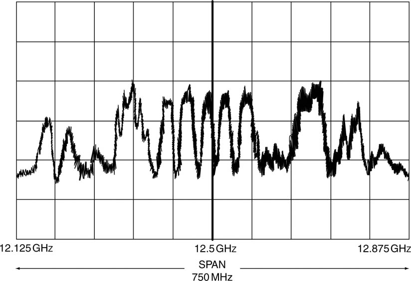
To see the transmissions on Astra 2B, the LNB will need to cover the frequency range of 12.25–12.75 GHz (they are available for different receive frequency bands) – this will also enable transmissions on Telecom 2C to be seen. Using a spectrum analyser that operates over the L-band, set the controls as follows:
(1) Set the centre frequency to the equivalent local oscillator (LO) frequency of the LNB for 12.5 GHz. Supposing the LNB has a LO frequency of 11.30 GHz, then the centre frequency should be set to 12.5 GHz–11.3 GHz = 1.2 GHz (1200 MHz).
(2) Set the span (i.e. the frequency swept across the display) to 750 MHz (i.e. 375 MHz either side of 12.5 GHz).
(3) Set the amplitude reference level to around −40 dB. This would be a typical output from an LNB receiving signals from a DTH satellite.
(4) If you now align the antenna to Astra 2C, you should see a spectrum analyser display similar to that shown in the diagram overleaf.
Typical spectrum analyser display from a satellite
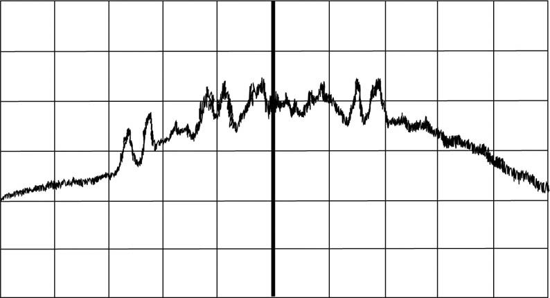
Having found the ‘reference’ satellite, you can now realign the antenna to the desired satellite, and if all is well, you will be able to find it relatively easily. You will need to make iterative adjustments to the azimuth, elevation and polarization to correctly align the antenna.
Finally, you should call the satellite operator’s control centre, and double check that the satellite signal carriers you can see at various frequencies confirm with what the satellite operator is radiating from the satellite.
Typical DTH satellite traffic spectrum analyser display
If you cannot find it, then it may be for one or more of the following reasons:
• You have misread the compass and/or inclinometer, and are looking at the wrong part of the sky
• You have miscalculated its position if using the reference satellite method
• the LNB is not the correct one for the band you are seeking
• the LNB is faulty or not working
• the information you are using is out-of-date.
Satellites also typically transmit a beacon signal, but these are usually such small signals that the typical SNG antenna is too small to receive them. Of much more use is if the satellite operator control can switch on a small pure carrier signal (i.e. no modulation) so that the uplink operator can have the spectrum analyser lined up to identify on the centre frequency of the analyser – the carrier should then pop up right in the middle of the spectrum analyser screen, and the uplink operator can then adjust the polarization of the SNG antenna to optimize this signal.
So to summarize, to set up an uplink, the operator needs the following
equipment in addition to the actual uplink transmission equipment:
• compass
• clinometer
• satellite position table
• spectrum analyser
• satellite programme listings
• satellite receiver and picture monitor