Setting up a link
Let us look in more detail at how the microwave link is set up for our live news transmission covering our story of the police shooting.
The ENG truck arrives on site at the hospital, as we said earlier, and the operator has to pick a spot which will enable a ‘live’ to be undertaken successfully (so it has to be within easy cabling distance of where the reporter is going to stand) but most importantly where the raising of the mast is going to be safe. Therefore, a spot has to be picked which is clear of any potential risks from overhead hazards – electricity supply cables, telephone lines, tree branches, etc.
Most links vehicles have stabilizers – either one or two pairs of retractable legs – which are designed and fitted so that the inevitable rock in the vehicle suspension is minimized. This is important as the effect of people climbing in and out of the van can make the mast rock, causing the microwave beam to go off target alignment.
The stabilizers are either fitted as a pair at the rear of the vehicle, at the middle of the vehicle, or there may be two pairs at the front and rear. The number and position is dependant on the size and length of the vehicle, in combination with the maximum extended height of the telescopic mast.
Having picked the spot, the ‘links operator’ deploys the stabilizers (if fitted) and then raises the mast. It is absolutely crucial that the operator clearly watches the mast as it rises, as a cable snagging or an unseen overhead obstruction can suddenly cause a serious accident.
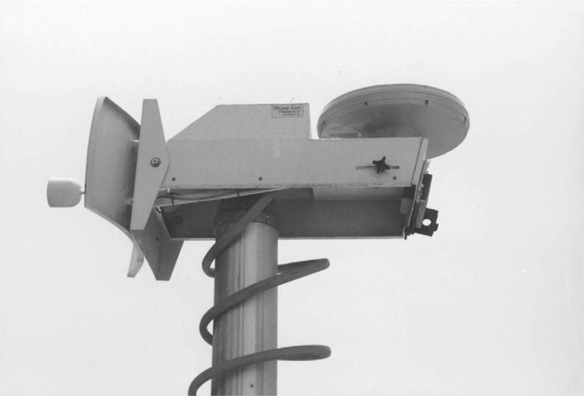
The equipment at the top of the mast is connected to the equipment below by means of either cables, which are bunched together and ‘loomed’ to the mast at each mast section junction, or they are enclosed in an expanding plastic sheathed coil which extends as the mast rises. The sheathed plastic coil is typically known as a ‘Nycoil’, which is a brand of brightly coloured air-brake hose which you often see connecting a trailer to a commercial tractor unit. This type of polyurethane hose is highly suitable for carrying cables up a retractable mast, as it automatically collapses in a ‘kink-proof’ fashion.
The mast is now fully extended, and we are ready to align the link. The operator calls the studio or master control room (MCR) back at the station, either by a dedicated radio channel if the station has its own radio channels, or using a cellphone. (Refer to page 59.)
As we saw earlier, the frequency band used for microwave links is divided up into channels (just like the channels on your TV set) and the channel that is going to be used will probably have been assigned for this particular story – so let us say the operator is told by the station that he is to use channel 5, and that happens to be at a frequency of 2.58 GHz with horizontal transmit polarization.
Stabilizer controls
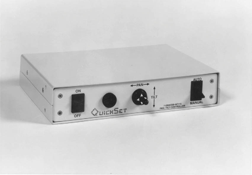
The operator then needs to align the ENG truck antenna so that it is pointing approximately in the direction of the microwave receiver. The operator can do this by remotely controlling the pan and tilt head at the top of the mast. (Refer to pages 59 and 60.)
Nycoil (the red tubing) on a mast with an antenna
Quickset control panel (© Quickset Inc.)
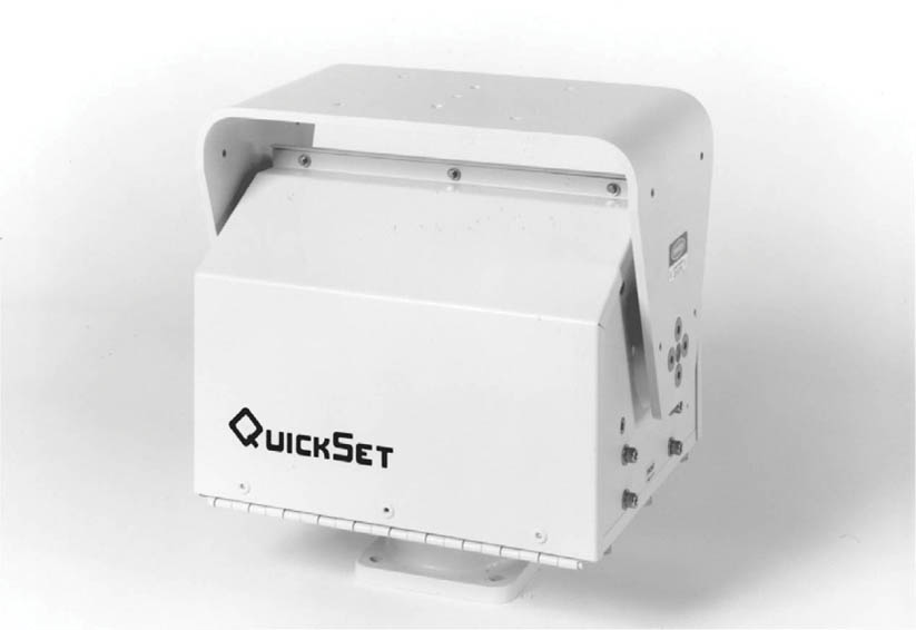
Quickset pan and tilt head (© Quickset Inc.) – without the transmitter and antenna
The receiver antenna may either be at the TV station itself or perhaps on a nearby high point – a building, hill or even a mountain! In this case there will be permanent circuits that connect the receiver to the station that carry not only the received video and audio signals, but also allows the station to remotely control the receiver equipment and antenna at the reception site, as shown opposite.
The operator will first switch his microwave transmitter into transmit on channel 5, with a test signal applied – typically colour bars on the video, and a 1 kHz steady tone on the audio channels. The operator will usually have some kind of ‘ident’ on the colour bars – the number of the truck and/or its location – and then check with the MCR at the station whether they can see his signal. It is very unlikely that they will initially, so the operator is talked in by the operator in the MCR at the station to achieve optimum alignment of the link. This is done as follows.
The operator makes a horizontal sweep of the arc of about 30° on either side of the direction of the microwave receiver (we describe this as the azimuth). If everything is alright, the MCR engineer, who is watching the output from the microwave receiver (set to channel 5 frequency and the antenna selected to the correct polarization) will call out to the truck operator (either via mobile cellphone or a radio) as soon as a flicker of the transmitted signal is seen. The truck operator will then make fine adjustments to azimuth from side to side to ensure that the receiver is ‘seeing’ the main signal lobe.
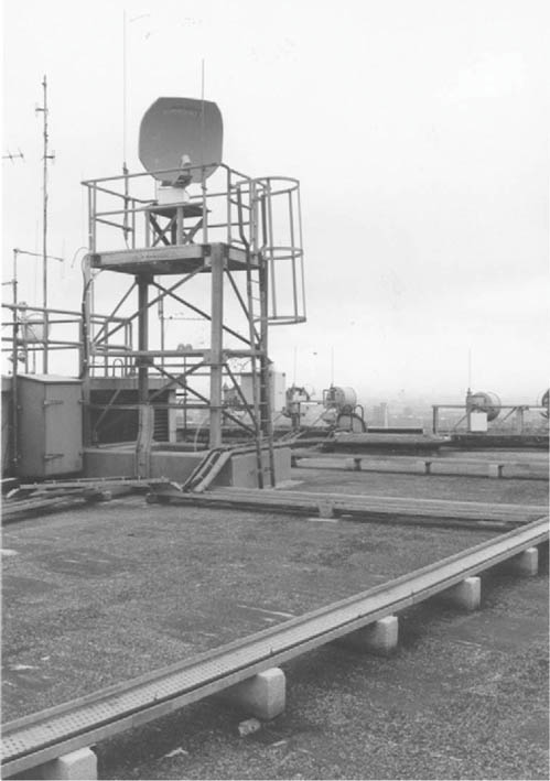
Central London receive point on a rooftop
The transmit antenna will actually radiate a main lobe (the maximum signal strength) and a number of weaker side lobes. In the MCR it is possible to be fooled that you have actually found the main lobe when in fact you may have optimized on a side lobe – which could lead to problems later if the weather worsened, or some other anomaly occurred.
The truck operator should sweep the antenna so that the MCR operator can see both the main lobes and the weaker side lobes – the main lobe can then be clearly identified as the one that generally gives the strongest signal.
The MCR engineer will not only rely on visual cues to identify the main and side lobes – the receiver produces a reading called the automatic gain control (AGC). It is not necessary to understand exactly what the AGC is – in short, it produces a reading on a meter or display that is a measurement of the received signal strength. The MCR engineer will know when the truck operator has pointed the antenna in the optimum direction by a mixture of the received video and audio signals seen and heard, along with the AGC reading.
Having aligned on the main lobe in the horizontal (azimuth) axis, the truck operator – with the MCR engineer still watching – will adjust the alignment of the antenna in the vertical (elevation) plane. This should again be a peak when the transmit antenna is exactly on axis with the receive antenna.
The MCR engineer may suggest that the truck operator tries a ‘tweak’ in elevation if it proves difficult to find a peak in the initial azimuth sweep. Unless the link is very strong and easily established, the whole process of aligning the link is an iterative process, so that the very best received signal can be obtained.
Some stations have steerable receive antenna rather than a fixed one, so the MCR engineer may steer the receive antenna to also optimize the receive end of the link once the truck operator has made all the azimuth and elevation adjustments at his end.
What is important is that the process is carried out in a methodical manner – if both ends of the link are steered at the same time, the process becomes chaotic and confused. Each ‘end’ must be clear about both what they are doing and what the other ‘end’ is doing.
So what are the common errors made in aligning the link? Some of these may seem obvious and stupid, but anyone experienced in setting up microwave links will recognize these errors because they will all have made them at one or another!
• Not having the correct azimuth bearing for the transmitter and the receiver (i.e. pointing the wrong way!)
• The transmitter and the receiver not being on the same channel (frequency)
• The transmitter or the receiver being set to the wrong polarization
• The transmitter or the receiver not being switched on (it happens!)
With the link correctly aligned and optimized for the best reception of the signal, the MCR engineer checks that the video and audio levels are correct, and that the communications with the truck are working.
The MCR engineer then routes the video and audio from the remote microwave to the studio.
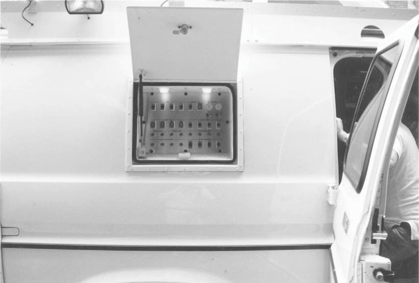
The truck operator will then check that all the connections have been made via the cable termination panel (CTP) on the vehicle, which allows for the video, audio and talkback/IFB connections to and from the live camera position, as shown opposite.
The studio will then talk directly to the operator in the truck, and check communication with the reporter (often referred to as the ‘talent’). As we have seen, communication with the reporter is all important, as for the typical ‘live’ shot there is likely to be a fair few questions and answers bouncing back and forth between the studio and the remote location – the hospital in our case.
From this point on, the work involved in maintaining the microwave link is limited to the MCR engineer keeping an eye on the incoming signal. The operator in the truck will be focussed on ensuring that the comms are working and the reporter is ready to go ‘live’. The studio will then come to the reporter, who will do the ‘live’ insert.
After the ‘live’ shot, the reporter and/or the operator will check whether anything more is required from that location, and if not, pack up and move on to the next location or back to base.
Cable termination panel on a truck