
Fresnel zones
Water, in the form of humid air, fog or rain absorbs microwave energy and can disrupt transmissions. At the middle point between a transmitter and a receiver, the beam can spread in diameter up to tens of metres and this area, known as the Fresnel zone, must be completely clear of obstructions such as trees, buildings, or any area of ground such as hills. Fresnel zones are all about ‘reflections’.
Fresnel zones
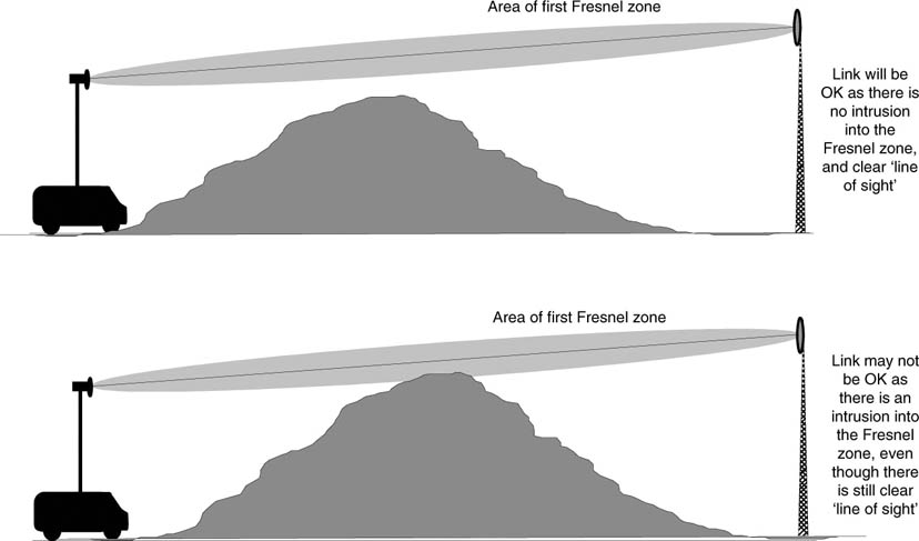
The mathematical theory surrounding Fresnel zones is very complex, and so we need to concern ourselves only with the area described as the first Fresnel zone. There should not be any obstruction within this area, as it is likely that a reflection will cause an ‘opposing’ signal to be bounced off the obstruction towards the receiver. When it arrives at the receiver, it would either add or subtract from the original direct (non-reflected) signal.
If the reflected radio wave is in phase with the direct signal then the reflection has an adding effect, and so improves the received signal. On the other hand, if the radio wave arrives out of phase relative to the direct signal, the reflection has a cancelling effect on the directly received signal.
This is known as multipath fading, and has at the very least a ghosting effect on pictures, which is seen as a one or more faint copies of the original image displaced to the left or right of the picture on the screen. At worst, it results in no signal being received at all.
These effects on the radio wave path are further complicated by the earth’s curvature, which can affect the radio wave due to atmospheric anomalies such as ducting and layering.
During certain parts of the day and night the atmosphere causes the radio wave to ‘bend’ according to atmospheric conditions. You would have probably noticed that as the TV signal at home is affected by very hot conditions in the summer or very cold dry weather in winter, the microwave link can also be affected in the same way.
For temporary ENG links, this can give rise to unforeseen problems as there is rarely time to ‘design’ the link as you would do for a permanent installation, where you would carry out careful calculations relating to the topography and extremes of weather that might be suffered during the year.
Ghosting
Instead, it is all a matter of getting out to the location and getting pictures back. However, for a major event that is known about beforehand, it is possible to check link path performance.
You can do this in two ways. First, by use of specialized software tools, a path profile calculation can be performed. Such software packages have a database containing digitized map information.
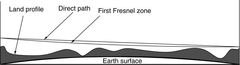
The program creates a path profile from topographical map information in the database based on the location of the TX and RX points, which be translated into an elevation profile of the land between the two sites on the path – a cross-section of the land underneath the signal path.
Earth’s curvature is calculated and added, as that of any known obstacles. The Fresnel zone calculation can then be applied and any potential clearance problems displayed.
Secondly (and often the easiest and certainly the most reliable), you can actually go out and perform a site test or site survey, using a microwave truck, from the event location back to the receiver.
This will give a very good measure as to whether the link for the event will work – except consideration must still be given as to whether the link path is likely to be affected on the day by weather conditions, or any local obstructions that may cause problems.
Typical path profile
For instance, are there trees within close distance to the transmitter, which may be in leaf when the event occurs? Links are rarely affected when ‘shooting’ through bare trees – but can be dramatically attenuated when trees are in leaf.
If the link path crosses tidal waters, it may be affected by the tides themselves, and it has been known for a link to work in the morning when it is first set up, and successfully used for the lunchtime news bulletin – only for it to fail during the afternoon as the tide has come in or gone out!
The other factor that could be calculated is a link budget – which is often part of the software packages. However, these are rarely calculated for ENG microwave, and the principles of link budgets will be covered later when we look at SNG, where they are of more significance.
Fade margin
The difference between the operating level of the link and the point at which it fails, because the power level reaching the receiver is too low, is called the ‘fade margin’. Normally, the fade margin will be set to overcome link impairments such as multipath, diffraction, refraction, polarization and absorption losses. We see the same term used in satellite links as well.