
Basic digital SNG system
Before we look in detail at SNG systems, we need to clarify why in this book we are only going to consider digital and not analogue SNG systems.
Since around 1994, digital SNG uplinks have been made possible by the development of low bit-rate digital compression encoders. The development of digital compression encoders that could run at bit-rates as low as 8 Mbps created an opportunity for use for SNG, and this in turn led to the realization that more channels could be fitted on a satellite, which led to lower costs to use the satellite. So the advantage offered was lower power uplinks and narrower bandwidth channels on the satellite, offering the possibility of lower satellite charges. Instead of a 27 MHz channel for an analogue signal, a digital signal could be fitted into 9 MHz (nowadays often less), hence improving the efficiency of use by a factor of three.
The advances in the equipment for digital operation led in general to a reduction in size. Less power is required for digital operation, so antennas and amplifiers could be smaller, and so cost less. Later on, it was realized that by the use of digital ‘multiplexing’, several programme paths could be provided more cost-effectively than by the multiple RF chains which are required in the analogue domain.
Analogue systems were in common use in Europe until the mid-1990s, and in the United States to the present day. Satellite operators have encouraged the transition to digital in each market as it became ready, though there are a few markets where there is still usage of analogue SNG. Readers interested in this particular area should refer to the author’s book ‘Satellite Newsgathering’, as this deals with both analogue and digital systems in much more detail.
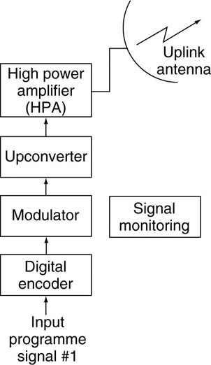
Basic DSNG system
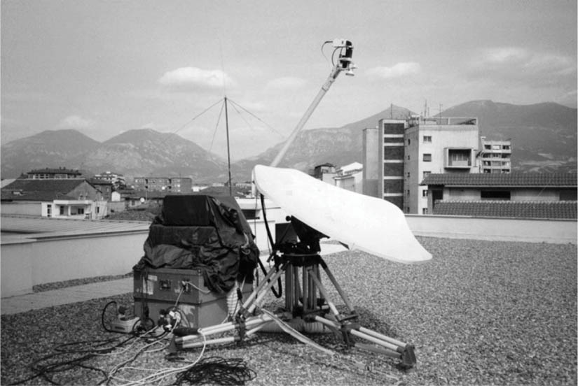
Typical DSNG setup
Frequency bands of operation
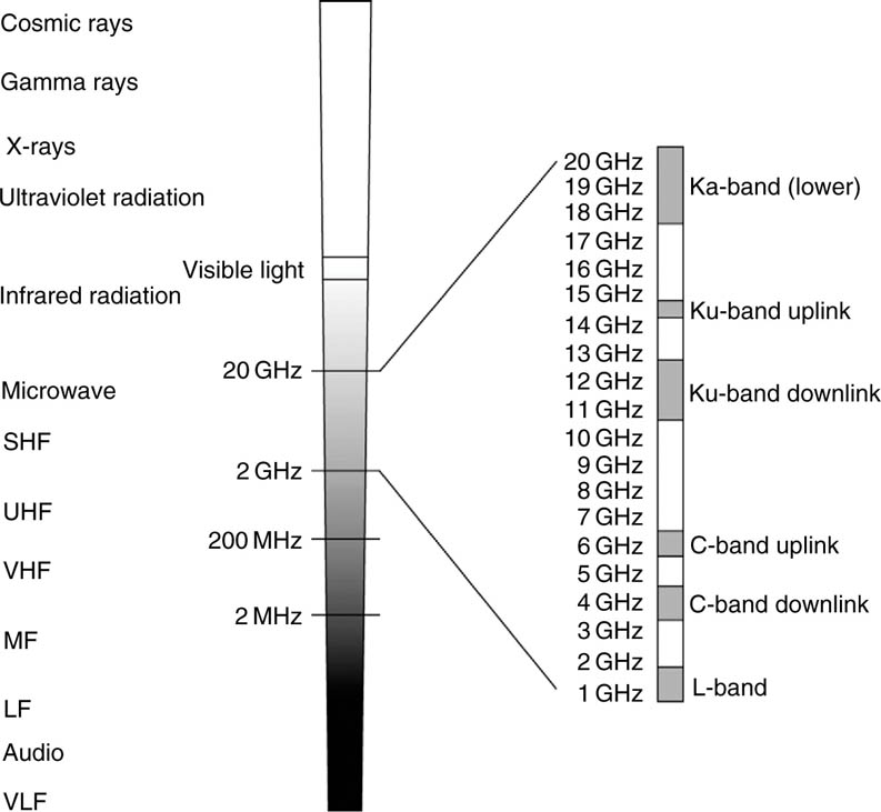
There are two principal frequency bands used for satellite transmissions for TV, which include those used for SNG. The band in the frequency range of approximately 4–6 GHz is called the C-band, and the frequency band in the range of approximately 11–14 GHz is called the Ku-band, as shown in the figure opposite.
C-band
The C-band is the frequency band that has been used for telecommunication transmissions since the 1960s. The transmit frequency band is typically in the range of 5.8–6.5 GHz, and the receive frequency band is 3.4–4.8 GHz, and as far as SNG is concerned, C-band is used exclusively for digital transmissions.
C-band does have some limitations from a regulatory aspect, as its use for SNG transmissions is not permitted in Europe and many other areas of the world. The problem in developed countries is that this particular frequency band is widely used for terrestrial microwave links in fixed telecommunication networks.
On the other hand, the attraction of C-band for SNG transmissions is that in some other parts of the world there is no ad hoc satellite transponder capacity in the Ku-band available for SNG usage. Equally, in these same areas there is often no sophisticated telecommunication infrastructure to limit C-band SNG transmissions.
C-band can be used for analogue transmissions, but requires large uplink powers resulting in the requirement for large antennas and amplifiers. Hence for SNG we use lower power digital transmissions in the C-band, with antennas and amplifiers similar in size to those used in Ku-band systems.
Spectrum showing satellite bands
Ku-band
The Ku-band is the frequency band that is now, in many parts of the world, the predominant band for TV (particularly DTH services) and is the dominant frequency band for SNG.
The transmit frequency is typically in the range of 14.0–14.50 GHz, and the receive frequency is split into three bands, 10.95–11.7 GHz, 11.7–12.25 GHz and the upper band of 12.25–12.75 GHz.
It is used widely in areas that have a developed telecommunication infrastructure, such as Europe and the United States.
The antennas are small and the uplink powers required, are relatively modest. Hence very compact digital SNG systems can be easily transported between locations.
Dual band
Since 1995, a number of manufacturers have offered dual-band systems. They are termed dual band as the RF section of the system (which includes the HPA and the antenna) spans both the C- and Ku-bands.
The operational advantage is obvious for flyaways, as with a single system the user has the choice when travelling to a location of being able to operate in either frequency band, subject to satellite capacity being available and no regulatory restrictions.
The principal global newsgatherers find these systems particularly flexible, as it is not necessary to decide before departure which band the system is going to operate in, since the choice of frequency band can be left until arrival at the destination if available space segment cannot be determined at the time of deployment.
The additional components to enable the system to operate in both bands are relatively minor. It is simply a matter of making a front panel selection on the HPA to change bands. The only other component that is altered is the feed arm, and that generally fits onto the same antenna.
The only disadvantage of a dual-band system is the increased cost, as a separate feed arm for each frequency band has to be purchased, and a dualband HPA is generally more expensive.
Polarization
The transmission of signals to and from satellites in either frequency band has the same property we saw earlier in terrestrial microwave – that of polarization.
Both circular and linear polarizations are used for satellite communications, and the signal is transmitted and received via the feedhorn – the assembly on the end of the arm extending out from the antenna.
This either delivers the signal into the focus of the transmit antenna on an uplink, or receives the signal via the focus of the receive antenna on a downlink.
The polarization on an SNG antenna can be adjusted by typically rotating the feedhorn, although some manufacturers provide adjustment by rotating the complete reflector and feed assembly.
As with terrestrial microwave links, the property of polarization is one of the defining parameters for a satellite transmission. Suffice to say that, in general, circular polarization is used in transmissions in C-band, and linear polarization is used in the Ku-band.
What is the reason for having different polarizations? Principally, the property of polarization allows the maximum utilization of frequency bandwidth on the satellite, as it enables the reuse of identical frequencies on the opposite polarization on the satellite.
Again, just to remind you from earlier, an antenna switched to one particular polarization will not detect or be interfered by signals on the opposite polarization, even when they are at an identical frequency.
However there is one important distinction from terrestrial microwave – which is a direct point-to-point system.
A satellite uplink transmitter has to transmit to the satellite downlink receiver via a satellite – it is an indirect point-to-point system. In general, in satellite transmissions, a signal transmitted (uplinked) from the ground on a particular polarization is received on the ground (downlinked) on the opposite polarization.
The uplink and the downlink antennas have operationally adjustable polarization (due to the effects of the position of the satellite and the effects of the Earth’s curvature).
However, the significant element of a DSNG system is compression, so we need to look at this in more detail before we look at the whole uplink–downlink process.