
SNG antennas
We now come to the focal point of the uplink – the antenna. The function of the antenna is to take the signal from the HPA and both further amplify the signal and focus the beam towards the satellite. Although there are a wide variety of antennas used in satellite communications, SNG uplink systems always use a parabolic type, similar to what we saw earlier in terrestrial ENG microwave. Downlink reception systems also use parabolic antennas.
We have already looked at the characteristics of parabolic (dish) antennas earlier in considering terrestrial microwave, so what are the differences seen in an SNG dish?
To recap, a parabolic surface produces a parallel beam of energy if the surface is illuminated at its focus, and the parabolic dish is commonly referred to as the reflector. The signal is transmitted via the feedhorn assembly on the antenna, and this is often loosely referred to as the waveguide, feed or ‘launcher’ (as it ‘launches’ the signal).
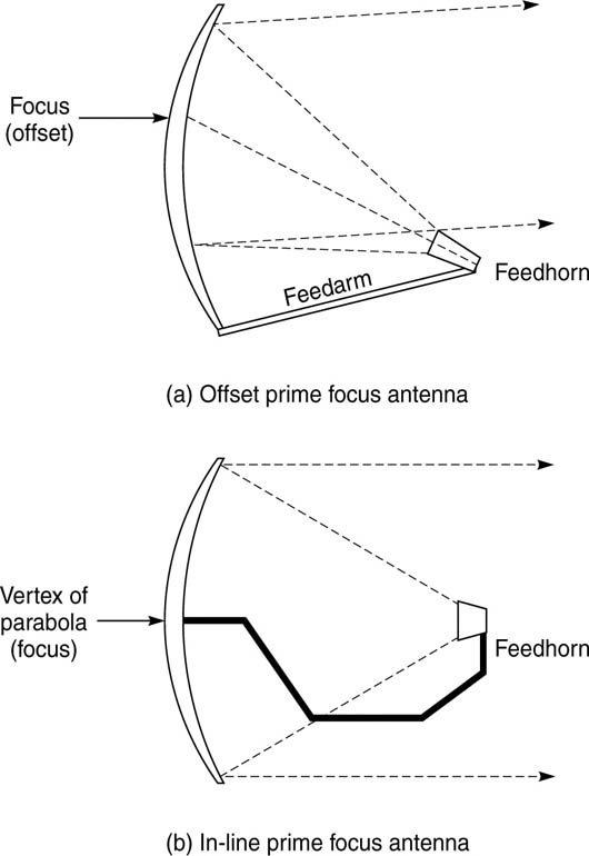
The parabolic antenna family has a wide number of variants, but the types used for SNG systems are primarily the ‘prime focus’ and ‘offset prime focus’ types.
Antenna types
A parabolic antenna is fundamentally described by two parameters. The physical diameter of the antenna is expressed in metres, and the amplification factor (gain) of the antenna is measured in dBi.
The construction of the antenna varies according to the application, varying depending on whether it is to be used in a flyaway or is mounted on a vehicle as we shall look at later. All antennas now have to meet the requirement of being able to operate to satellites spaced only 2° apart in the geostationary arc. The reason for the demand for 2° spacing is that in the 1980s it was anticipated that the number of satellites was going to steadily increase, with a resulting need to move satellites closer together to increase capacity in the geostationary arc.
This means not interfering with satellites adjacent to the intended one, and therefore the radiation pattern from the antenna has to be accurately defined.
The gain figure is the single most important descriptor of the antenna, as together with the power output rating of the HPA, the total system power is defined by adding the HPA dBW figure to the dBi figure from the antenna. This gives us a measurement called the Effective Isotropic Radiated Power (EIRP).
As an example – and this might look a bit complicated but it is necessary to look at it – a 180 W HPA produces 22 dBW, and a 1.5 m antenna has a gain of 45 dBi, and by adding these two figures together we have a maximum system EIRP of 67dBW – a typical uplink power requirement for a Ku-band DSNG system. Normally the system does not need to run at maximum theoretical power (and it can cause a few problems), and the typical amount of power for a DSNG uplink to work on the current generation of satellites is below 60 dBW (which is significantly less). It can be complicated measuring in dBs, as they are not a linear measurement, so for our purposes here, this is as far as we need to go. However, as a comparison, analogue SNG systems would typically need over twice this amount of power (near to 70 dBW).
Feedhorn polarization
Earlier we discussed the property of polarization. As we saw earlier in terrestrial ENG microwave, the two types of polarization – circular and linear – are each further subdivided, and determine how the signal is transmitted from the feed-horn. A signal uplinked on one particular polarization is typically downlinked on the opposite polarization. Ku-band signals are generally linearly polarized, while C-band signals are often circularly polarized – but there are exceptions.
On both the uplink and the downlink, the feedhorn is additionally rotated to compensate for the angular difference between the antenna position on the Earth’s surface and the satellite position. This is referred to as polarization ‘skew’, and the degree of skew can be calculated from the latitude and longitude of the uplink (or downlink). Particularly for linear polarization, it is critical in achieving a good transmission or reception of a signal that the polarization skew is correctly applied to the antenna.
It is also important that any receive antenna is as ‘blind’ as possible to signals on the opposite polarization – this is termed cross-polar discrimination (XPD) – so that any potential interference from a signal on the same frequency but opposite polarization is minimized.