Now that we have covered the method of breadboarding your Pi and some of the electrical components that you might use in your circuits, we can talk about putting these into practice with our Banana Pi. We will start with some simple circuits and move on to the process of controlling motors through the GPIO pins.
The simplest circuit that we can make (aside from just a little wire!) is lighting up an LED. You can consider this as the "Hello World" of electric circuits. For this, we are going to need an LED (any color), some jumper wires (two pieces), and a resistor. The resistor needs to be between 270 Ω and 330 Ω. If you go higher than that, the LED will be dimmer than usual. With too much current, the LED will be very bright before it burns right out.
This is a very simple circuit. We will connect a wire to the 3.3V pin and the ground pins. It doesn't matter which Banana Pi you are using, though you may need to refer to the chart from the first chapter to reference the pins. I am using the M2 for this example. The following image shows the pins that I am using:
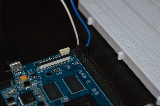
I have created a simple circuit by connecting a white jumper to the 3.3V pin (top left) on the M2. This pin goes to the breadboard and is plugged into the same rail as the anode of an LED. This LED leads to a resistor, which prevents excessive current from passing through the circuit. The blue jumper is connected to the other end of the resistor on the negative rail, which is plugged into the ground pin on the Banana Pi. In the next image, you can see the circuit that I created:
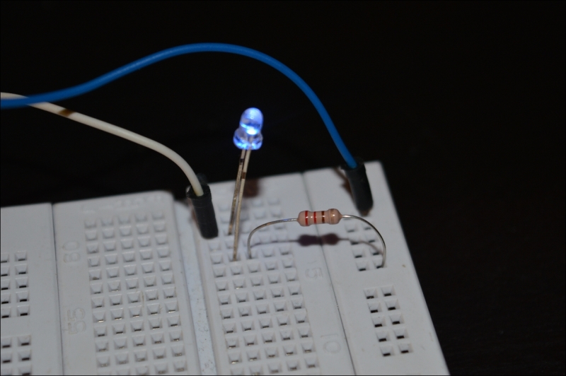
Note that we were able to create this circuit without the use of code. We can enhance this circuit by writing a bit of code to make the LED blink.
Now that we have created a simple circuit using our Banana Pi, we can interact with it by using a bit of code. We will revisit the Python coding language that we talked about in a previous chapter. Let's start by moving the jumper on the 3.3V pin and move it to pin 12, which represents GPIO 21. You can refer back to the chart if you need to, but it is the 7th pin down the left side of the board.
We need to create a simple script. Let's start by importing what we will need to use the time package and the GPIO pins:
import RPi.GPIO as GPIO
import time
We will need a function to blink a pin. We will fluctuate between turning the LED on and off every second by using the following code:
def blink(pin):
  GPIO.output(pin,GPIO.HIGH)
  time.sleep(1)
  GPIO.output(pin,GPIO.LOW)
  time.sleep(1)
  return
This simple function will be the section of our code that actually handles the current that is being supplied to the LED. Now, we need to set up the pins and the mode. We will accomplish this with the help of the following code:
GPIO.setmode(GPIO.BOARD)
GPIO.setup(21, GPIO.OUT)
Now that our pins are initialized, we want to loop a few times over the blink function to make the LED actually blink. If we just call the function once, we will only see the LED turn on and then turn off. So, let's set up a for loop that will iterate 50 times, calling our function each time:
for I in range(0,50)
  blink(21)
Now, we will call the cleanup() function with the help of the following code:
GPIO.cleanup()
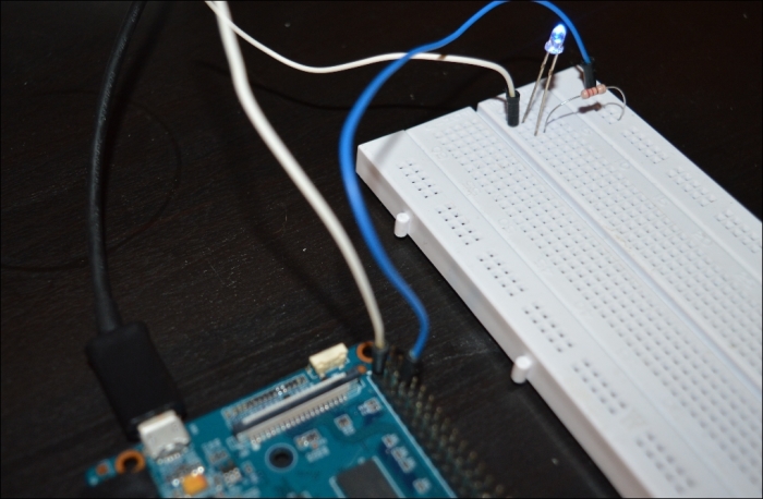
The preceding function will clean up all the ports that we used. This will only affect the pins that we used in our program (21). This is because programs don't necessarily end just because they have hit the bottom of the script. Our pin will still be initialized after the loop, which means that it will still be in the memory. By calling this function, we can reinitialize the pin later on when we need to use it again. Here is a picture of my circuit:
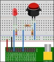
Now, we have a simple circuit that can be controlled by code. Let's add some user input to our project. We will connect a button to the breadboard and use the input to light up our LED. In the end, our circuit will look like this:
We are going to need the following additional hardware:
- Two additional jumper wires
- A button
- A 1K Ohm resistor
- A 10K Ohm resistor
We will start by connecting the LED to the 270 Ohm resistor and the 3.3V input. We are going to connect the button to the pin numbered 22 and a 10K Ohm resistor. When the button is pressed, the circuit diverts the power from the 3.3V pin to the pin numbered 22, which bypasses the 10K Ohm resistor. The 1K resistor is there to protect the Banana Pi.
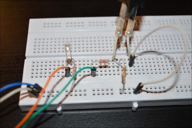
When all of this is on the breadboard, it will look like this:
Now, we will write some more code in Python to make the LED light up when the button is pressed.
So, in this script, we are going to make the LED on pin 21 blink when the button on pin 22 is pressed. To start out, we will import the packages that we need to start our project just like before, in the following way:
import RPi.GPIO as GPIO
import time
Now, we are going to set up the GPIO pins that we will be working with. Again, this will be similar to our last script, except for the fact that, in this case, we will be using two pins:
#Set up GPIO
GPIO.setwarnings(false)
GPIO.setmode(GPIO.BCM)

#Set up pins
GPIO.setup(21, GPIO.OUT)
GPIO.setup(22, GPIO.IN)
We will set up an infinite loop, which will set the value of the LED to the button being pressed, with the help of the following code:
While True:
  GPIO.output(21, GPIO.input(22))
  time.sleep(0.05)
The preceding code will cause the LED to light up when the button is pressed. You can save this script and run it with Python on the Banana Pi. Now try pressing the button.
We have pretty much mastered the art of working with LEDs. We will now move on to something more fun.
One of the most popular things that you can work with now is servo motors. Servos are small electric motors that are popular in robotics and several other related projects. We will write a small script that will allow us to control a servo motor.
The following image shows a servo motor:

We will use the Pi to control the position of the servo. For this project, we are going to need the following components other than your Pi:
- A servo motor
- Three jumper wires
- A breadboard
We will connect the servo to three pins on the Banana Pi. Unlike a stepper motor, we can safely connect the stepper directly to the Pi without having to use a bunch of resistors or integrated circuits. We will also write a simple script that will be a little more complex than our previous scripts. With this script, we will be able to directly control the stepper motor.
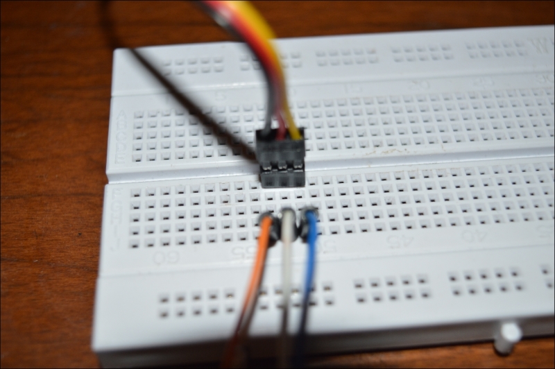
First, we will connect the red wire (servo +5V) to the breadboard. On the same rail, we will connect a wire to pin 4 on the Banana Pi. Next, we will connect pin 6 on the Pi to the breadboard, which will then be connected to the black wire on the servo (-5V). Pin 11 is our PWM signal. This will be connected to the yellow wire from the servo. When we are done, the circuit will look like this:
Now that we are all wired up, we can write our Python script.
We have our servo connected to our Pi. We want to control the position of the servo by using a script. We will start by writing a new script:
nano servo_controller.py
The first thing we want to do is import our packages and set up the GPIO pins like our previous scripts, as follows:
import RPi.GPIO as GPIO
import time

# Set up GPIO
GPIO.setwarnings(False)
GPIO.setmode(GPIO.BOARD)
GPIO.setup(11, GPIO.OUT)
Now let's output some instructions so that we know what keys to press in order to move the servo. This is optional, but we will add it in case we forget which keys to press, as follows:
print "l : Left"
print "r : Right"
print "m : Middle"
print "q : Quit"
Now, we need to add some code that will listen for the correct keys and act appropriately. If the L key is pressed, we will move the servo to the left. If the R key is pressed, we will move the servo to the right. We can also move the servo to the center position and quit our program.
First things first. We need to set up an infinite loop that will run and listen for the keys that we will be pressing. We also need to define the servo (we will define that on pin 11), as follows:
While True:

  Servo = GPIO.PWM(11, 50)
  Servo.start(2.5)

  input = raw_input("Selection: ")

  if(input == "r"):

  elseif(input == "l"):

  elseif(input == "m"):

  elseif(input == "q"):

  else:
    print "Input not recognized"
Now, we need to handle the different keys that are pressed. Right now, we have a script that listens for input and then filters the script down to a specific piece based on which key was pressed.
First, we will handle the R key when it is pressed. We want to see how many steps we have to take towards the right based on the input from the user. We will then loop the function as many times as we are told and move the servo to the right. We will receive input from the user, as follows:
if(input == "r"):

  steps = raw_input("Steps (1 – 10): ")
  steplength = 12.5 / int(steps)
Now, we will iterate as many times as the user has input and move accordingly, as follows:
for Counter in range(int(steps)):
  Servo.ChangeDutyCycle(stepslength * (Counter + 1))
  Print stepslength * (Counter + 1)
  time.sleep(0.5)

time.sleep(1)
Servo.stop()
We will handle the process of moving towards the left next. This is similar to what we just did:
elseif(input == "l"):
  Servo.start(12.5)
  steps = raw_input("Steps (1 – 10): ")
  stepslength = 12.5 / int(steps)

  for Counter in range(int(steps))
    Servo.ChangeDutyCycle(12.6 – (stepslength * (Counter + 1)))
    time.sleep(0.5)

  time.sleep(1)
  Servo.stop()
Next, we need to handle M. This will move the servo back to the middle position. This is almost like a reset switch for our script, which can be implemented in the following way:
elseif(input == "m"):

  Servo.start(7.5)

  time.sleep(1)

  Servo.stop()
Now, we will handle exiting the script and cleaning up the GPIO pins when the user selects Q in the script, as follows:
elseif(input == "q"):

  os._exit(1)

  Servo.stop()

  GPIO.cleanup()
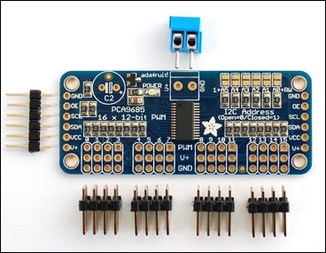
Now, when you run the script, you will be presented with the selections. Based on your input, the Banana Pi will control the servo and move it in the direction of your choosing. This is our first interactive script. You can apply what we did here to all kinds of sensors and components, which will be covered in the next chapter. You can take things a step further and control multiple servos by using a servo controller, such as the one shown in the following image:
Our complete script looks like this:
import RPi.GPIO as GPIO
import time
import os
# Set up the GPIO
GPIO.setwarnings(False)
GPIO.setmode(GPIO.BOARD)
GPIO.setup(11, GPIO.OUT)
print "l : left"
print "r : right"
print "m : middle"
print "t : test"
print "q : exit"
while True:
Servo = GPIO.PWM(11, 50)
Servo.start(2.5)
input = raw_input("Selection: ")
if(input == "r"):
steps = raw_input("steps (1 - 10): ")
stepslength = 12.5 / int(steps)
for Counter in range(int(steps)):
Servo.ChangeDutyCycle(stepslength * (Counter + 1))
print stepslength * (Counter + 1)
time.sleep(0.5)
time.sleep(1)
servo.stop()
elif(input == "m"):
Servo.start(7.5)
time.sleep(1)
Servo.stop()
elif(input == "l"):
Servo.start(12.5)
steps = raw_input("steps (1 - 10): ")
stepslength = 12.5 / int(steps)
for Counter in range(int(steps)):
Servo.ChangeDutyCycle(12.5 - (stepslength * (Counter + 1)))
time.sleep(0.5)
time.sleep(1)
Servo.stop()
elif(input == "q"):
os._exit(1)
Servo.stop()
GPIO.cleanup()
else:
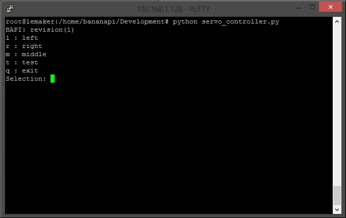
print "Input not recognized"You can save this as servo_controller.py and run it from the command line by using the following command:
python servo_controller.py
The following screenshot shows the output of the program that we just wrote: