
Since we are directly connecting the LCD to the Banana Pi, we will wire it up. We won't have a GPIO header to connect directly to. Displays of size 16 x 2 generally have 16 pins. These devices are generally easy to work with. The different pins can be broken down into the following types:
- Data pins: These are the pins that send data to the display. These pins are pretty straightforward.
- Register Select pin: This can be used to move the display up or down or even clear it.
- Read/Write pin: This pin allows you to read and write to the LCD. This will almost always be in write mode. However, on rare occasions, it will be in read mode to allow us to read from the display.
- Enable pin: This is a simple pin that allows us to write to the registers on the LCD.
The following image shows an HD44780 LCD (16 x 2) pins labeled:
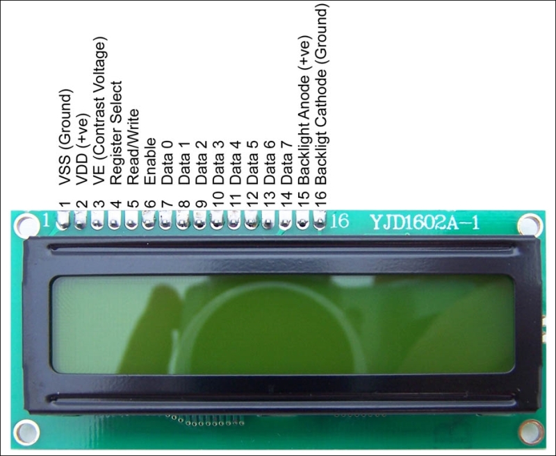
Pin definitions for a standard 16 x 2 LCD display can be seen in the following table:
|
Pin |
Definition |
Symbol |
|---|---|---|
|
1 |
GND |
VSS |
|
2 |
+5V |
VDD |
|
3 |
Contrast adjustment |
V0 |
|
4 |
H/L Register Select signal |
RS |
|
5 |
H/L Read/Write signal |
R/W |
|
6 |
H/L Enable signal |
E |
|
7 |
H/L Data bus line |
DB0 |
|
8 |
H/L Data bus line |
DB1 |
|
9 |
H/L Data bus line |
DB2 |
|
10 |
H/L Data bus line |
DB3 |
|
11 |
H/L Data bus line |
DB4 |
|
12 |
H/L Data bus line |
DB5 |
|
13 |
H/L Data bus line |
DB6 |
|
14 |
H/L Data bus line |
DB7 |
|
15 |
+4.2V |
A |
|
16 |
Power supply for back light |
K |
Since we are working with the Banana Pi, it is important to verify that the LCD display you are using has an LED backlight as opposed to an EL backlight. EL backlights use a lot more power and are cheap to get, but will not pair well with any Pi. Displays with LED backlights have built-in resistors. If they don't, the Pi could be damaged. Most modern displays use LED backlighting now.
Now that we have identified the pins on the LCD, we can match them up with GPIO pins. We will need to breadboard this at first (you can make a PCB later on). We will start by connecting the +5V (pin 2) power to the positive line on the breadboard and the GND pin (pin 1) to the black or negative line.
Now we can wire up the display to receive data from the Banana Pi. We will need a potentiometer (knob!) on the circuit as well. We will connect pin 3 to the potentiometer's middle prong. Pin 4 will connect to the negative line on the breadboard. Pin 6 will connect to pin 24 on the Banana Pi.
We will skip several pins. They are not necessary for what we are doing right now. These pins are 7, 8, 9, and 10; they are all data pins. Pin 11 connects to GPIO 23. Pin 12 connects to GPIO 17, and pin 13 connects to GPIO 21. Pin 14 connects to GPIO 22. Finally, pin 15 will connect to the red line, or positive rail, and pin 16 will connect to the ground.
Here is the schematic of the wiring diagram:
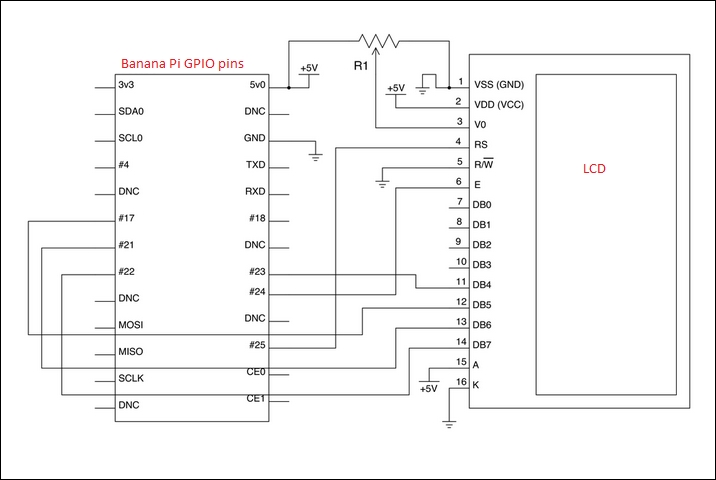
It is important to not send 5V from the LCD display into the Banana Pi, which is 3.3V. You need to make sure that there is proper resistance in place or use something like a Pi Cobbler from Adafruit when you breakout to the breadboard. You can hurt your Pi if you don't.
We have wired up our display now. We want to write some text to the screen. We will, of course, need to make sure that the proper packages are installed. We installed the Python developer packages earlier, but just in case you skipped ahead, you will need to install them:
sudo apt-get install python-dev
sudo apt-get install python-setuptools
sudo apt-get install python-pip
We will also need the RPI GPIO library we used earlier in the book. You can conveniently find this library at https://github.com/LeMaker/RPi.GPIO_BP.
A single command will download the package from GitHub onto the Banana Pi:
git clone https://github.com/LeMaker/RPi.GPIO_BP -b bananapi
You can easily install this library by running the following few commands:
sudo apt-get update
sudo apt-get install python-dev
cd ./RPi.GPIO_BP
sudo python setup.py install
Now we will grab a script from Adafruit's GitHub. They wrote this script for the Raspberry Pi and to work with LCD displays, but it will work just fine for us:
git clone git://github.com/adafruit/Adafruit-Raspberry-Pi-Python-Code.git
Now we can use this script to test and change directories to the project and run the scripts to see the output. Now we want to take the music playing from the radio and display information on the LCD.
We will start by pulling another repo from GitHub. This repo is by Bob Rathbone and includes some good scripts, such as ada_radio.py, which will allow us to output the music to the display:
git clone [email protected]:bobrathbone/piradio.git
We can use these scripts to bridge the gap between our LCD display and MPD. There are a few useful programs we will use. This will be even more useful if you are using a display such as the Adafruit complete display.
Although these tools are developed by Adafruit, they are useful in other situations as well. We will start the ada_radio script now:
python ada_radio.py start
This command will start the script, and the display should start to show on the LCD. The content displayed is coming from the MPD library we installed earlier. The information from that program is being logged to the display.