
Over the past few chapters, we covered some fairly big-picture topics, such as how to have Silverlight work in and out of the browser and how to use XAML. Those are all important to understand in order to create Silverlight applications that work in or out of the browser. XAML and the property system are also important, and we build upon that knowledge in every subsequent chapter, including this one.
In this chapter, we're going to dig back down under the covers and look at some fundamentals of the core user interface base classes and the rendering and layout systems that make everything fit on the screen and render to the user.
Silverlight's rendering process involves a number of steps, and has provisions for several developer-provided optimizations to the process. Silverlight also has a far more advanced layout system than simple left/top positioning of elements on the screen. The multipass layout system handles measuring and arranging elements across the entire visual tree.
Once the rendering, layout, and core object fundamentals are down, we'll have some fun with performing 2D transformations on our objects. If you've ever wanted to rotate or scale an object on the screen, you'll find the section on render transformations to your liking.
Of course, if you have 2D, you always want one more, so we also have 3D transformations. You can do some wild things with the power of the PlaneProjection and the Matrix3dProjection classes. The former is great for most use cases, including the ubiquitous CoverFlow scenario. The latter is one of the most powerful transformations in Silverlight. If you've ever wanted to do something akin to a 3D-rotated, sparsely populated, and z-layered deep zoom, you'll definitely get a kick out of the power of the 3D matrix.
We've covered the fundamentals of XAML already, so let's start with the base classes that underlie all those angle-bracketed elements that make up the user interface: the UIElement and FrameworkElement classes.
In previous chapters, we saw examples of TextBlocks, TextBoxes, and other controls and elements. All of the UI elements in XAML are FrameworkElement items, so they're also inherently UIElement items because FrameworkElement inherits from UIElement.
A UIElement is an object that represents a visual component. These types of elements have built-in support for layout, event handling, and rendering. Although this extremely generic description may seem pointless, it isn't. In fact, by deriving from this type, a large majority of the elements within Silverlight share the same types of features. These features are exposed through a number of extremely valuable methods and properties.
Throughout this section, we'll cover the methods and properties that you'll probably use most often. It's important to recognize that some of these belong to the FrameworkElement class, while others belong to the UIElement class. We'll point this out as we go along but, for now, let's begin by addressing some of the common properties.
The UIElement and FrameworkElement classes expose a number of properties common to all of the visual elements in your application. Because of the abstract nature of the UIElement and FrameworkElement classes, these properties may be set on any control in a variety of scenarios.
In this section, we'll start with a look at cursors and then look at how to make your entire element partially or completely transparent. Sometimes, transparent isn't good enough and what you really want is to have the control logically removed from the visual tree, so we'll look at the Visibility property. From there, we'll look at how to align an element in the horizontal and vertical spaces. Finally, we'll cover how to set margins to give your elements a little breathing room and how to snap the layout to whole pixels so your lines look crisp and fully rendered.
When a user navigates the mouse cursor over a FrameworkElement, the cursor will change to indicate the type of action the user can take. For instance, when you hover around a Canvas, you'll see a basic arrow. Alternatively, if you move your mouse over a HyperLinkButton, you'll see a cursor that looks like a hand. But, you can use whatever cursor you want by setting the Cursor property; for example, using the Stylus cursor with a TextBlock:
<Canvas Cursor="Hand" Background="Green" Height="60" Width="180">
  <TextBox Cursor="Stylus" Height="20" Width="60" />
</Canvas>
This example uses two nondefault cursor options: Stylus and Hand. These options represent Cursor items, each of which is accessible through the System.Windows.Input.Cursors class. This class exposes nine statically visible Cursor properties:
ArrowEraserHandIBeamNone
SizeNSSizeWEStylusWait
This shows the values you can use in a FrameworkElement's Cursor property. These cursor options provide an excellent way to communicate with your users. Most of these options reflect the cursor options found in Cascading Style Sheets (CSS). But, short of newer advances in the proposed HTML 5 spec, it'd be a challenge to find a W3C CSS equivalent for our next property: Opacity.
The Opacity property represents an element's transparency. By default, this double-precision value is set to 1.0, which means the element is completely visible. You have the flexibility to set this value as low as 0.0, making it completely transparent. To get a feel for how the Opacity property renders content, look at figure 6.1, which shows a TextBlock with varying Opacity values.
The Opacity values ensure that a UIElement is visible. If you set the Opacity value to 0.0, the element wouldn't be visible. But, just because a UIElement can't be seen, it doesn't mean it's not there. Instead, even if a UIElement has an Opacity of 0.0, it'll still behave as though it can be seen. For instance, a transparent element will still respond to mouse events. If you want to completely hide an element, you must change the Visibility property.
The Visibility property gives you the ability to toggle whether a UIElement can be seen and whether it participates in layout. By default, all UIElement objects have a Visibility of Visible. This ensures that a UIElement can be seen and occupies its allotted layout area. If you set the Visibility of a UIElement to Collapsed, no layout area is reserved for the UIElement. Consider the StackPanel in listing 6.1.
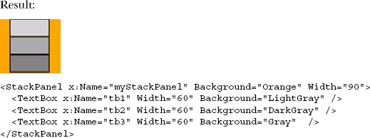
Listing 6.1 shows three TextBox elements. By default, each of these elements has a Visibility of Visible. Watch what happens when the Visibility of the middle TextBox is set to Collapsed, as in listing 6.2.
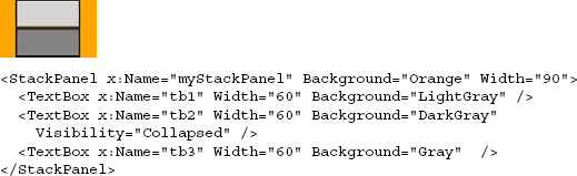
Listing 6.2 highlights the effects of Collapsed. The TextBox with the name tb2 isn't shown. You could just set the Opacity to 0.0, but the layout space wouldn't be freed. In addition, using the Opacity property to hide an element can be wasteful; an element with an Opacity of 0.0 still participates in the layout and rendering. Elements with a Visibility of Collapsed skip the rendering stem and report no size in the layout steps.
Cursor, Visibility, and Opacity all affect visible portions of the UIElement, but not the layout. The alignment properties typically have a great impact on the layout of an element, depending upon the panel in which the element is hosted.
Every FrameworkElement gives you the opportunity to specify how it should be aligned within its parent. This alignment setting will trickle down through the object tree and affect the alignment of all child elements—well, at least until another FrameworkElement sets its alignment. You have two ways to align visual elements.
Visual elements can be aligned both vertically and horizontally by setting the VerticalAlignment and HorizontalAlignment property values to one of the acceptable values. These values belong to two separate enumerators, aptly called VerticalAlignment and HorizontalAlignment.
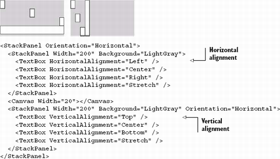
Listing 6.3 shows the effects of all four HorizontalAlignment options and all four VerticalAlignment options. The HorizontalAlignment property accepts the Left, Center, Right, and Stretch values, whereas the VerticalAlignment property accepts the Top, Center, Bottom, and Stretch values. The alignment properties behave differently depending upon the container in which the UIElement resides. For example, they have no effect when put into a Canvas due to the Canvas panel's lack of layout functionality.
Both properties default to their Stretch values. Because the Stretch options alter the rendered height or width of an element to take up the maximum amount of space available, you may want to consider giving the element some breathing room with the Margin property.
Similar in nature to the Padding property, the Margin property enables you to specify a cushion, but this specific cushion works outside the bounds of a FrameworkElement. This cushion can be set using a single value or a space-delimited or comma-delimited list of four values just like the Padding property, as shown in listing 6.4.
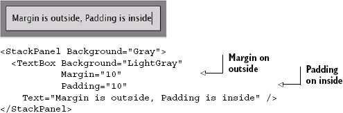
Listing 6.4 shows the Margin and Padding properties working together. The Padding property is valid in this code because this property is exposed by the System.Windows.Controls.Control class. This is explained further in the next chapter. For now, it's important to recognize that the Padding property isn't accessible to all FrameworkElement items, but the Margin property is.
Margins and padding can alter the location of contained elements, sometimes pushing them to subpixel locations and making them look fuzzy. Luckily, Silverlight has the UseLayoutRounding property to help us avoid that.
Silverlight supports aligning elements on subpixel boundaries. An unfortunate side effect of this is the loss of crisp lines. Sometimes, you really want that 1 px line to be just 1 px thick and not antialiased to 2 px in thickness.
One simple way to avoid this problem is to place your elements on whole pixel locations. But when your element is nested inside a panel, which is inside a control, which is in a stack panel located in another grid—all of which can have margins, padding, and other properties affecting layout—you can't easily calculate exactly where your element will appear.
Silverlight supports a property of the UIElement called UseLayoutRounding. When UseLayoutRounding is set to true, the layout system (see section 6.3) will round the points of your element to the nearest whole pixel. When false, Silverlight will respect the subpixel location of the points and won't attempt to move them. Listing 6.5 shows the impact of layout rounding on two rectangles. The first rectangle has layout rounding turned on; the second has it turned off.
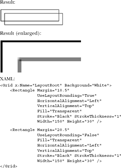
In listing 6.5, you can see that the rectangle that isn't rounded to the nearest pixel has lines that are two pixels thick and light gray. When viewed in its native resolution, it looks fuzzy. When layout rounding is turned on, the result is a crisp line with sharp corners and no fuzz.
UseLayoutRounding is respected by almost every element in Silverlight. The Polygon class exposes this property but ignores it. Polygons are expected to be complex shapes where layout rounding wouldn't really make sense, so layout rounding is a no-op.
Note
When sharing code with WPF, it's important to note that layout rounding is turned on by default in Silverlight. This is in contrast to WPF, where it's turned off by default.
We covered the Margin property as well as the useful HorizontalAlignment and VerticalAlignment properties. In addition, we also highlighted the value of the Visibility, Opacity, and Cursor properties. Finally, we looked at how to scare away the fuzzies with UseLayoutRounding. Collectively, these represent some of the more widely used properties of the FrameworkElement and UIElement classes. But these properties only serve to describe an element. There are times when you need to perform an action on them; in these scenarios, you need to rely on their methods.
Two common tasks are often performed during runtime. The first task involves managing attached properties. The second involves finding an element within the element tree. We'll cover each of these in detail.
Every UIElement is a DependencyObject. A DependencyObject gives you the ability to retrieve and change attached property values. Consider the process of altering the position of an element within a Canvas. Although you might initially think to set the Canvas.Left and Canvas.Top properties, you'll quickly run into a wall. Instead, you must take advantage of the SetValue method as shown in listing 6.6.
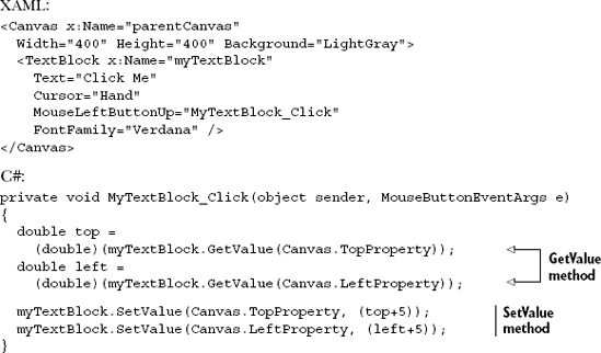
When a TextBlock is clicked and the click event raised, it'll move five pixels down and to the right. This is made possible by retrieving the current Left and Top positions of the TextBlock within the Canvas through the GetValue methods. Then, the TextBlock is moved within the Canvas using the SetValue methods. But where do the TopProperty and LeftProperty values come from?
These properties are DependencyProperty elements—a special type of property designed to depend on information from multiple sources, covered in chapter 2. For instance, as shown in listing 6.6, you use two DependencyProperty (specifically attached properties) attributes—Canvas.Left and Canvas.Top—to position the TextBlock. At the same time, there could be an animation affecting the TextBlock, so the position of the TextBlock would be dependent upon both the layout panel (the Canvas) and the animation. (Animations are discussed in chapter 22.)
Thanks to the DependencyProperty, it's incredibly easy to manage or retrieve the value associated with an attached property. Dependency properties also provide several other advantages discussed in more detail in section 2.1.4. For now, let's look at how to find elements within the element tree.
As described in chapter 2, the Silverlight Object Model is represented as a hierarchical tree of elements. Considering that each element in this visual tree is, at its core, a FrameworkElement, you have the flexibility to navigate this tree. With this element, you have the ability to go either up or down the tree.
To go down the tree, you must call the FindName method. This method takes the name of an element and retrieves it. It doesn't matter if the element is a child, grandchild, or located even further down the tree. The FindName method will retrieve it as long as it's a descendent. If it isn't found, the method will return null.
Alternatively, if you need to find an element up the tree, you use the Parent property to recursively navigate up the tree and search the sibling nodes, as described in chapter 2.
Finding elements is a task that you may need to perform in certain circumstances, such as when you dynamically load XAML. Once these elements are found, you can readily get or set the attached property values of a UIElement using the GetValue and SetValue methods. These methods aren't difficult to understand, but the process of using a DependencyProperty to set the value of an attached property may seem strange at first. As you grow more familiar with it, it's easier to see the power of this approach, which can lead to new ways of delivering a rich and interactive user experience.
The UIElement and FrameworkElement classes form the base of everything that's rendered in Silverlight. We've seen that they offer a number of useful properties and methods to control everything from their alignment, to visibility, to how opaque they should appear. Now that we understand the capabilities they offer, it's time to take a step back and look at the rendering process as a whole, in which the UIElement and FrameworkElement play a core role.
User interfaces in Silverlight are complex. They often have multiple layers of semitransparent or overlapping content, animation, video, and more. The level of problems the runtime must solve is more akin to that of a gaming platform than, say, something like Windows Forms.
The problem is made even more complex by the restrictions and capabilities of the various browser platforms. Most browsers have a simple threading model, varying sandboxed capabilities, and what can only be described as personality.
It's important to understand the rendering process, especially as it relates to performance. In this section, we'll cover some of the highlights of the process, including browser threading, drawing, performance optimizations, and how you can plug into the process using the callback function.
The rendering process can be broken down into the steps described in table 6.1.
Table 6.1. The steps of the render process
Step | Description |
|---|---|
Update hosted HTML | Get updated visuals for the hosted |
Clock tick | Increment the animation and video clock. |
Event handlers | Run the user code in event handlers, except for the per-frame render callback. |
Layout | Measure and arrange elements for display. Because this is one of the most important steps in this process, we'll cover this in more detail in section 6.3. |
Per-frame render callback | Run the per-frame callback |
Rasterize | Rasterize the vector content, media, images, and more onto their intermediate render surfaces. Then composite to the back buffer. |
Show Frame | Show the frame in the browser. Blit (direct memory chunk copy; short for bit block transfer) the back buffer to video memory or to the software rendering surface. |
More than just that happens, of course. There's user code, media decoding, network access, and so on, but this table captures the essence of the rendering process. Though it can help to conceptualize this as an ongoing loop, the individual steps trigger off timers and window messages and not off a single cycle timer, it'd be slightly inaccurate to do so. Nevertheless, just as we still refer to the various timer- and event-driven processes in game development as the game loop, it's a reasonable abstraction.
This process is continually optimized from release to release and even across devices. For example, the Windows Phone 7 process, though similar to what I've just described, actually runs the animations on a separate thread.
One of the most significant limitations of the rendering process for any browser plug-in is the UI thread. Each browser offers up one UI thread per process, shared across all plug-ins in that process. For some browsers, the scope of a process is a single tab; for others, it's the entire browser.
Of the preceding steps, a few demand additional explanation. Specifically, the clock tick, the per-frame render callback, rasterization, and layout all require more detail. We'll start with an explanation of rasterization and the various steps involved in it and then look at how we can plug into the process via the render callback. Finally, since it's a much larger topic and arguably is the most important one to understand, we'll cover layout in section 6.3. Before that, let's look at a few of the other steps, starting with the clock tick.
Animation and video in Silverlight are governed by clock time and not by frame rate. Because of this, Silverlight can skip frames on the machines that can't keep up while still maintaining the correct real time of the media or the animation frames shown. In other words, an animation that lasts two seconds will last two seconds on a slow machine and on a fast machine.
The clock tick on Windows happens at 60 frames per second at the most (it happens to be capped at 30 frames per second on the Windows Phone 7). If you set the Silverlight MaxFrameRate to a value lower than that or the system can't keep up, the tick will happen at a lower rate but will ensure the time remains correct. Figure 6.2 shows an example of the dropped frame approach.
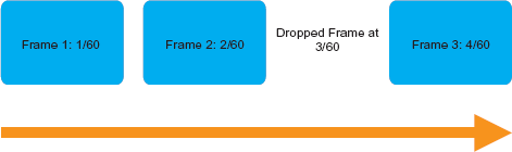
Figure 6.2. If the machine can't keep up with the workload, Silverlight will drop frames but will ensure that the displayed frames are correctly synchronized with the clock tick.
Figure 6.2 shows a theoretical dropped frame. Both frames 1 and 2 are at their correct times. What would've been frame 3 (timed at 3/60 of a second) was dropped, so the next presented frame, the new frame 3, picks up at the correct time. This prevents the undesired effect of slow-running animations or movies.
After the clock has ticked and all the animations and media elements incremented, the next step is to call an optional per-frame rendering callback function.
There may be times when you want to perform an action during every frame that's rendered on the screen. That may be a simple as keeping a count of frames, swapping a back buffer to simulate an immediate-mode rendering system, or performing game loop-style operations.
Silverlight includes the Rendering event on the CompositionTarget class, which is suitable for these tasks. CompositionTarget.Rendering is an event that fires once per frame, allowing you to synchronize code with the rendering system.
There's no guarantee that the callback will happen at the max frame rate. Though it often does work out this way, many factors, including the amount of work being done inside the callback and the overall speed of the system, contribute to how often this runs. You can generally expect the callback to happen once per frame, assuming your code is well-behaved.
Listing 6.7 shows how to wire up the Rendering event and show the current timestamp.
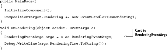
Note the cast to RenderingEventArgs in listing 6.7. This is pretty unusual and not something you'd intuit without knowing something about the underlying code. The underlying code is actually sending an instance of RenderingEventArgs, but the event signature is just regular EventArgs. By casting to RenderingEventArgs, we gain access to the RenderingTime property, which we can use to synchronize our logic to Silverlight's own rendering process.
Note
CompositionTarget.Rendering may not have a 1:1 correspondence with the actual rendering frame rate. For example, a static scene with no changes may require no actual render, but CompositionTarget.Rendering will still fire at the expected frame rate.
The event signature uses EventArgs simply for historical reasons. The additional property was added late during the WPF v1 development cycle, and it was considered too late to introduce a new event signature—a breaking change. Silverlight strives to maintain WPF compatibility whenever possible, so the same signature was carried over to Silverlight.
You can modify layout inside this callback, but that'll cause another layout pass to happen. For that reason, you may want to consider other approaches to avoid the double layout tax on each frame. We'll cover layout in detail in section 6.3. Before we do that, let's look at another processing-intense operation in this cycle: rasterization.
Rasterization is the process of turning the vectors in the vector cache into their bitmap representation. Though not exactly rasterization by that definition, we'll also include video and image blitting in this process.
In this section, we'll cover the basics of how rasterization works, including the order of the steps. Then, we'll look at some optimizations in the process and, finally, dive into the use of caching and hardware acceleration to improve performance.
The most fundamental aspect of rasterization that you'll need to understand is the order in which elements are rasterized.
As you recall from chapter 2, elements in Silverlight are organized into the visual tree. This tree has a single root and it branches off into hundreds or thousands of nodes depending upon the complexity of what's on the screen.
The structure of that tree is key to the rendering process. For any branch of the tree, Silverlight rasterizes elements in the visual tree in the following order:
Children
Cache
Opacity mask
Opacity
Effects (intermediate surface)
Clip
Projection (intermediate surface)
Render transform
Layout offset (internal layout transform)
Parent node
This is a recursive process; it starts at leaf nodes (the furthest children) and works its way back to the root.
Note that the clipping happens after the opacity calculations. One performance consideration is that a large shape that has opacity other than 1.0 and has only a small portion shown due to clipping (manual or via a panel) can waste a fair number of CPU cycles due to the opacity calculation. Similarly, effects are also calculated prior to the clip and have even more impact on performance.
The intermediate surfaces mentioned are all bitmap caches that are later composited together. Note that the Writeable bitmap is a special case because it essentially is an intermediate surface of its own.
The rendering process involves a recursive traversal of the visual tree, with optimizations to eliminate branches of the tree that have been already cached and haven't changed. Another optimization is the handling of occluded pixels.
I used to play around with 3D rendering. One of the most basic performance optimizations you'd make is the culling of occluded triangles. When 3D objects are rendered in 2D, the surface is typically broken down into many planar triangles. You'd check to see whether the normals (the direction the surface faces) for the triangles are pointing away from you and you are, therefore, looking at the back side of a triangle. If so, you'd remove the triangle from the pipeline. You'd also then check to see if there are any triangles that are completely covered by other triangles.
Though a simplification, consider a complex scene where there's an opaque wall in front of you (the camera) and a bunch of complex shapes on the other side of the wall, as shown in figure 6.3. In such a scene, the shapes would be occluded by the wall; it'd be wasteful to include them in the rendering process.
Occlusion culling in a 3D system can be expensive to calculate. The least performant but most accurate approach would be to shoot an imaginary ray from the camera to each and every point in the geometry making up the shapes, and see if the ray must cross through any other geometry before hitting the target. If it does, then that point is occluded.
Surprisingly, in a 2D system such as Silverlight, where you can have transforms and effects that play into both the size and shape of elements and as varying degrees of opacity, occlusion culling is more complicated.
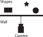
Figure 6.3. An overhead view of occlusion in a 3D system. The shapes are occluded by the wall; the camera can't see them. It'd be wasteful to include their geometry in the rendering process. Silverlight does occlusion culling at the pixel level rather than the shape level.
Silverlight doesn't handle occlusion culling at the shape level. Instead, it handles it at the brush pixel level. If you consider that performing blends between multiple pixels can be an expensive operation, it makes sense that Silverlight would optimize that process out of the loop for any pixels that wouldn't be visible in a frame.
This optimization does speed up rendering in most cases. But, if you know an element won't be visible on the screen and you either have many elements or that specific element is expensive to render, you'll want to set its Visibility property to Collapsed so that Silverlight doesn't spend any time on its rendering or layout. Similarly, you need to take into consideration the complexity of any alpha blending you perform, especially when there could be several layers of pixels in play.
One way to cut down on the number of layers and also avoid several other rendering and layout steps, is to cache segments of the visual tree into their own bitmaps.
Cached composition enables branches of the visual tree to be stored in bitmap form after the first rendering. (For the web programmers reading this, understand that the cache is a local in-memory cache on the client.) This bitmap is then used on subsequent frames until the elements change. For complex subtrees, cached composition can realize huge performance benefits. Figure 6.4 helps visualize how cached composition works.
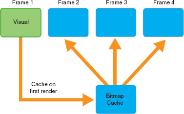
Figure 6.4. Cached composition in use. On the first render, or any layout change, the cache is updated with the result of the render. Subsequent frames use the prerendered contents of the cache.
On first render, any elements that have been marked to be cached are rendered as usual and then the output of that render is stored in the bitmap cache. Listing 6.8 shows how to enable caching for a group of elements in a Grid.
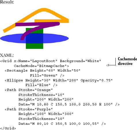
Listing 6.8 shows some Silverlight artwork (suitable for submission to the Freer and Sackler Galleries, no doubt!) composed of a number of shapes and paths. The paths here are relatively simple, but more complex artwork may be made of hundreds or thousands of points. The process of rasterizing complex artwork has a real CPU cost but, when cached, that cost is one time rather than per frame.
In section 6.4 we discuss render transforms. Render transforms can affect size and orientation of a group of elements. If you apply a render transform to a subtree that has been cached—for example, to increase its size to 200 percent—you may end up losing the benefit of the cache because Silverlight has to render at the larger size. Luckily, there's another form of the CacheMode property that enables you to cache the render at a different size. Listing 6.9 shows how to cache elements at four times their natural size.
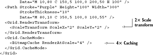
Note that the bitmap cache is set to a 4× render whereas I'm only using a 2× transform. That's a bit wasteful but certainly is allowed and useful, and you can always scale down without losing quality. If the RenderAtScale option hadn't been used, caching wouldn't have worked for this subtree of elements.
Caching the elements as bitmaps allows Silverlight to use hardware acceleration by keeping those surfaces as textures cached on the video card—assuming sufficient texture memory and assuming hardware acceleration has been enabled at the plugin level.
Once a tree of visual elements has been cached, you can take advantage of hardware acceleration for composting those elements with other layers in the application. In addition, hardware acceleration can benefit transforms, such as stretching and rotation.
In order to use hardware acceleration, you must set the EnableGPUAcceleration plug-in parameter to true. In chapter 4, we covered how to build up the object tag. Here's the line for enabling acceleration:
<param name="EnableGPUAcceleration" value="true" />
If your application is an out-of-browser application (chapter 5), you can set this via the OutOfBrowserSettings.EnableGPUAccelerationProperty, typically handled through the out-of-browser settings dialog.
Hardware (GPU) acceleration can help you realize real performance gains. But there can also be times when it's a net performance drain in your application. The main reason for this is the number of surfaces that must be created when hardware caching is used.
For each bitmap of cached content, Silverlight must then create two additional surfaces in video RAM: a surface to hold all content above the cached bitmap and one to hold the content below it. In an application with a large height/width on a machine with relatively low video memory (especially all those integrated graphics chips), you can quickly run out of memory should you try to cache too many separate subtrees.
When caching, especially when using hardware acceleration, you should endeavor to create as few bitmap caches as possible. When using acceleration, you may want to debug how the process is working. For that, you can use the cache visualization debug settings.
When performance is important, one thing that can really help is visualizing the bitmap caches in use in your application. Silverlight provides a setting that draws colored overlays on different regions in your UI, indicating which content is or isn't cached. Cached content shows up normally; uncached content shows up with a colored overlay.
Cache visualization is another parameter on the plug-in object described in chapter 4. The parameter is named enableCacheVisualization:
<param name="enableCacheVisualization" value="true"/>
You can also set this value via code, which is essential for debugging out-of-browser applications. The setting is the EnableCacheVisualization property of the Settings object:
Application.Current.Host.Settings.EnableCacheVisualization = true;
In both cases, this is a debug setting, so be sure to turn it off when you move your application to testing or production environments. The in-code approach allows you to turn the property on and off via a menu setting or similar approach.
Similarly, you can visualize redraw regions to see exactly what content Silverlight must redraw for each frame. Like cache visualization, this is an object tag setting:
<param name="enableRedrawRegions" value="true" />
When you enable this visualization, Silverlight will display redraw regions in a different color for each frame, making it obvious what elements are causing which parts of the interface to be redrawn at runtime. Just as with the other setting, this isn't something you want to leave enabled in production. Also with the other settings, this has a runtime-settable version especially useful for out-of-browser applications:
Application.Current.Host.Settings.EnableRedrawRegions = true;
Between the redraw visualization and the cache visualization, you should have a good start on debugging any rendering performance issues in your application.
Rasterization is an important process to understand in Silverlight, especially if you're creating an application, such as a game or media player, which is performance sensitive. Consider using cached composition and hardware acceleration to help you out but understand the limitations and where the point of diminishing returns lies for your application.
The rendering process as a whole has a number of important steps. Of those, the key steps to understand are the clock tick, which increments all the animation and media counters; the per-frame rendering callback, which is useful for game loops and similar operations; and the rasterization process.
One other important step we haven't yet covered is layout. Layout is important enough to require a more in-depth look than some of the other steps. In fact, of all of them, I'd consider layout the most important step for the majority of Silverlight developers.
Layout systems across different technologies vary greatly in complexity. Take, for example, the Windows Forms layout system. Fundamentally, that layout system involves absolute x and y coordinate pairs and an explicit or implicit z-order. Controls can overlap each other, get clipped on the edge of the window, or even get obscured completely. The algorithm is pretty simple—sort by z order (distance from the viewer) and then blit the bits to the screen.
For another example, look to HTML and CSS. HTML and CSS support elements that must size to content and page constraints (tables, divs), as well as support absolute positioning, overlapping, and so forth. It's more of a fluid approach, where the size and position of one element can affect the size and position of another. Therefore, the layout system for HTML and CSS is significantly more complex than that for something like Windows Forms.
Silverlight and WPF support both types of layout: content that self-sizes based on constraints, and content that's simply positioned by way of an x and y coordinate pair. Depending on the container in use, it can even handle laying elements out on curves or radially from a central point. The complexity that makes that possible deserves a deeper look.
Layout in Silverlight and WPF involves two primary passes: the measure pass and the arrange pass. In the measure pass, the layout system asks each element to provide its dimensions given a provided available size. In the arrange step, the layout system tells each element its final size and requests that it lay itself out and also lay out its child elements. A full run of measuring and arranging is called a layout pass.
In this section, we'll go through the layout system in more detail, especially these two key steps and their implications for performance and design. If you're curious about layout or you've ever been confused by something like Height and Width versus ActualHeight and ActualWidth, read on.
Whenever elements need to be rendered to screen due to having just been added, made visible, or changed in size, the layout system is invoked for an asynchronous layout pass. The first step in layout is to measure the elements. On a FrameworkElement, the measure pass is implemented inside the virtual MeasureOverride function, called recursively on the visual tree:
protected virtual Size MeasureOverride(Size availableSize)
The availableSize parameter contains the amount of space available for this object to give to itself and child objects. If the FrameworkElement is to size to whatever content it has, the availableSize will be double.PositiveInfinity.
The function returns the size the element requires based on any constraints or sizes of child objects.
Note that MeasureOverride isn't called directly from the layout system: it's a protected function. Instead, this function is called from the UIElement's Measure function, which, in turn, is called by the layout system.
The second pass of layout is to arrange the elements given their final sizes. On a FrameworkElement, the Arrange is implemented inside the virtual ArrangeOverride function, also called recursively:
protected virtual Size ArrangeOverride(Size finalSize)
The finalSize parameter contains the size (the area within the parent) this object should use to arrange itself and child objects. The returned size must be the size actually used by the element and smaller than the finalSize passed in; larger sizes typically result in clipping by the parent.
Similar to the relationship between the measure pass and MeasureOverride, ArrangeOverride isn't called directly by the layout system. Instead, the Arrange method on UIElement is called, which then calls the protected ArrangeOverride function.
At the end of the arrange pass, Silverlight has everything it needs to properly position and size each element in the tree. But it doesn't have everything it needs to actually display the element because its render position or size could be affected by a render transform, as covered in the previous section.
Despite the name, the LayoutCompleted event isn't technically part of the layout pass. Instead, it's fired as the last event before an element is ready to accept input. LayoutCompleted is the safe location for inspecting the actual size and position of the element or otherwise responding to changes in same.
Don't do anything in LayoutCompleted that would cause another layout pass. For example, don't change the size or position of an element, modify its contents, change its layout rounding, or otherwise manipulate properties that could change the size of the element's bounding box. If you have multiple nested layout passes and they take longer than the time allowed for that frame, the Silverlight runtime may skip frames or throw a layout exception.
The LayoutInfomation class in System.Windows.Controls.Primitives contains a few methods that are useful to folks implementing their own MeasureOverride and ArrangeOverride code. Specifically, GetLayoutSlot and GetLayoutClip are helpful when hosting child elements in a custom panel.
Regardless of its actual shape, each visual element in Silverlight can be represented by a bounding box or layout slot. This is a rectangular shape that takes into account the element's size and any margins, padding, or constraints in effect. Figure 6.5 shows the relationship between a layout slot and the child element hosted in a panel.
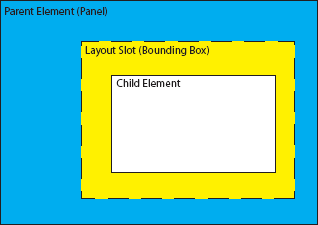
Figure 6.5. The relationship between the layout slot and the child element for an element smaller than the slot
The layout slot is the maximum size to be used when displaying an element. Portions of the element that fall outside the slot will be clipped. To see the layout slot for an element, you can call the static function GetLayoutSlot:
public static Rect GetlayoutSlot(FrameworkElement element)
The returned Rect will contain the bounding box or layout slot for that element. This return value can be useful when creating a custom panel or when debugging layout issues.
Sometimes elements may be larger than their layout slots, even after measuring and arranging have attempted to fit them. When that happens, you have a layout clip that represents the intersection of the child element's size and the layout slot.
Figure 6.6 shows the relationship between the layout slot, the child element, and the layout clip for that child element in an instance where the child element is too large for its slot.
The function GetLayoutClip returns the intersection that represents the layout clip. In this case, the function returns an actual geometry object, useful for setting the clip geometry for an element should you need to:
public static Geometry GetLayoutClip(FrameworkElement element)
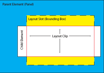
Figure 6.6. The relationship between the layout clip and the layout slot for a child element too large for its slot
The returned Geometry contains the intersection or null, if the element wasn't clipped. It should be noted that, in WPF, the GetLayoutClip method has a counterpart by the same name that actually resides on the UIElement and takes in the slot size and returns clip geometry.
Layout is a recursive process; triggering layout on an element will trigger layout for all the children of that element, and their children, and so on. For that reason, you should try to avoid triggering layout for large visual trees as much as possible. In addition, when implementing your own MeasureOverride or ArrangeOverride code, make sure it's as efficient as possible.
An example of this has to do with large collections of children in controls such as lists and grids. Drawing the elements takes a certain amount of time but that only happens for elements that are onscreen. Creation of the CLR objects representing the items also takes a certain amount of time. Most importantly for us, the measure and layout passes happen for all children, regardless of their potential position on screen or off. Therefore, if you have a thousand elements in a ListBox, MeasureOverride and ArrangeOverride will be called for each of them. More importantly, if those elements contain children (as often is the case with item templates), you'll have even more calls in the layout passes.
One solution to this is virtualization. A subset of the built-in controls (such as the DataGrid) support UI virtualization. For those, precreated elements are reused with new data. The end result is a reduction in the number of in-memory elements, as well as a reduction of MeasureOverride and ArrangeOverride calls.
Another performance consideration has to do with sizing and positioning elements. For example, if you change the margin of an element or modify its width or height, you'll trigger a layout pass. But, if you instead call a render transform to either move or resize that element, you won't trigger a pass. We'll cover render transforms in the next section.
Understanding the layout system helps take some of the mystery out of what happens when you size elements in Silverlight, and they don't quite do what you might've expected them to do. It's also a key concept to understand if you plan to implement your own panels/container controls.
WPF has the concept of a layout transform. This type of transform is parallel to a render transform but triggers a layout pass. As we've seen here, triggering a layout pass can be an expensive operation, especially if done inside an animation. For performance considerations and due to their relatively low adoption, layout transforms were omitted from Silverlight.
The render transforms provided by Silverlight are almost always adequate to solve problems we used to solve with layout transforms—and often superior. Let's look at them next.
The Transform element gives you the flexibility to alter the appearance of any UIElement within Silverlight. Transforms give you the flexibility to change the size, location, gyration, and angling apart from the other related properties that have been defined up to this point. The real value of transforms will become apparent when you learn about animations in the next chapter. But first, table 6.2 lists the ways UIElement objects can be altered.
Table 6.2. A list of the available transformation options
Transform | Description |
|---|---|
| Rotates an object by a specific |
| Provides a zoom in or out effect by specified amounts |
| Tilts an element by defined amounts |
| Moves an element by specified amounts |
| Not a type of transform; rather, a container that groups multiple transforms to be applied |
| Provides an easy way to combine the other four transforms |
| Provides a way to use a low-level matrix to perform multiple simultaneous transforms |
As table 6.2 describes, each Transform has its own special purpose. As you'll see within the next few sections, applying a transformation generally involves altering one or two basic properties.
The RotateTransform is responsible for rotating an object clockwise around a specified point by a specified angle. This rotation affects the local coordinate system of the rotated object. If you need to rotate an object in place, you need to specify the center point as the center of the object being rotated. Listing 6.10 shows a basic square rotated clockwise by 30 degrees. The dashed version represents the original square before the transform was applied.
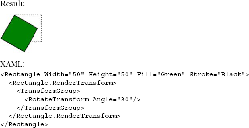
The Angle property specifies to rotate clockwise around the optional CenterX and CenterY properties, which default to 0. Because these values are initially set to 0, an element will rotate around the upper-left corner. If you set these values to the center of the object you're rotating, it'll give the element the appearance of rotating in place.
When rotating elements, sometimes it becomes necessary to rotate them counterclockwise. As you may have already guessed, you perform this task by providing a negative value within the Angle property. Note that an element will complete one full rotation if the Angle is set to 360 or –360.
The ScaleTransform enables you to expand or contract an object horizontally or vertically, empowering you to create the effect of zooming in or out. Listing 6.11 shows how a basic square was zoomed in on via a ScaleTransform.

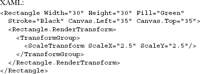
The ScaleX and ScaleY properties determine the magnitude by which to zoom in or out. As you may expect, the ScaleX property stretches or shrinks the element along the x-axis. The ScaleY property stretches or shrinks the element along the y-axis. If you provide the same value in both properties, the object will expand or contract proportionally.
You may have also noticed that the Rectangle expands from the upper-left corner. This is because the CenterX and CenterY properties determine the point from where the scale operation should take place. By default, these values are set to 0.
A SkewTransform warps the coordinate space in a divergent manner. By skewing or shearing an element, you basically slant the element in a direction. Listing 6.12 illustrates a basic square skewed by 18 degrees on both the x and y-axes.
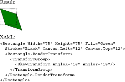
The AngleX and AngleY properties specify the amount to shear the rectangle horizontally and vertically. Much like the other transforms we've reviewed, the SkewTransform also exposes CenterX and CenterY properties to specify the horizontal and vertical origin of the skew rendering.
The TranslateTransform element allows you to define how to transfer an element from one location to another. Listing 6.13 shows a square translated by 25 pixels vertically and horizontally.
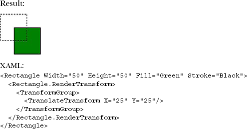
As this listing demonstrates, by specifying a double-precision floating-point value within the X and Y properties of a TranslateTransform, you can move a visual element horizontally or vertically. As you can imagine, the TranslateTransform and the other transforms mentioned give you a lot of flexibility with your visual elements. These transforms can be used to provide even more radical changes when you group them.
In the previous transform-related examples, you may have noticed the TransformGroup element. This element wasn't required when there was only one applied transform. However, it's usually a good idea to include it if there's any chance you'll be adding additional transformations and you aren't using the new CompositeTransform described in the next session. The TransformGroup element makes it possible to simultaneously define multiple transformations on a visual element in any arbitrary order.
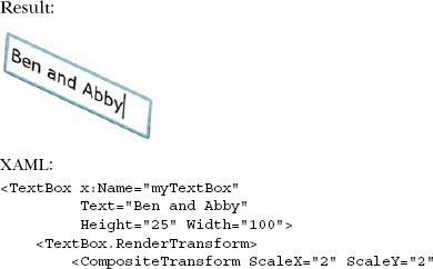
Up to this point, we've primarily used a Rectangle as the visual element for transformations but you can also apply these interesting renderings to any UIElement. You can apply these transformations to items such as TextBox elements, Buttons, the MediaElement, and so many more that you'll need to refer to the Silverlight SDK to see. For the sake of illustration, all the primary transforms that have been discussed are applied to the TextBox shown in listing 6.14.
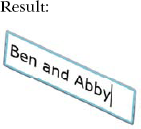
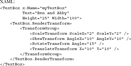
Although the use of transforms in this example is a bit over the top, it does accurately display the true flexibility provided by the transform elements.
Introduced in Silverlight 4, the CompositeTransform applies the four built-in render transforms using a single statement. Though a TransformGroup with all four transforms is still supported, you'll find this approach generally easier to use. The CompositeTransform applies the transforms in the following order:
Scale
Skew
Rotate
Translate
That's the order generally recommended for transformation. If you play with transforms much, you'll quickly find out that the order has a real impact on the final result. The transforms themselves are equivalent to the same individual transforms applied using a TransformGroup. Listing 6.15 shows the same example from listing 6.14 but now implemented via a CompositeTransform.
As you'd expect, the result is the same as the previous listing. But now the code is arguably easier to read, contains four fewer elements (three fewer transforms and no transform group), and is slightly more efficient due to the use of a single set of transformation matrices multiplied together in a single function.
Once all the tooling switches over to using this approach, it'll be much simpler to animate transforms without having to remember lengthy and error-prone property paths for the nested transform elements.
Having said that, we actually had the ability to do all of this in previous versions of Silverlight using the MatrixTransform.
MatrixTransform is a powerful class that's rarely used in Silverlight applications. Why? Because the idea of matrix math is, to many, something new. But all of the other transforms use matrix math behind the covers; it's just nicely shielded behind friendly property names.
The Silverlight transformation matrix is a 3×3 affine transformation row-major matrix. The size is three rows by three columns. Affine means that the edges all need to stay the same length (proportionally) as they originally were. All points on a single line in the original shape will remain in a single line in the resulting transformed shape. You can't do a true perspective transform in an affine matrix or other transform that would violate this. Row major means the vectors are expressed as rows and not columns.
As a result of the affine nature and row-major approach, the last column of the matrix will always contain the rows "0,0,1." Here's what the structure looks like, including the default values:
1 | 2 | 3 | |
|---|---|---|---|
1 | M11(1.0) | M12 (0.0) | 0 |
2 | M21 (0.0) | M22 (1.0) | 0 |
3 | OffsetX (0.0) | OffsetY (0.0) | 1 |
To perform a translate transform that moves the shape 10 pixels in the positive x-axis and 20 pixels in the positive y-axis, you'd supply 10 for OffsetX and 20 for OffsetY
To increase the x scale of the target, provide a value larger than 1.0 to the M11 property. Similarly, to increase the y scale, provide a value larger than 1.0 to the M22 property. Values smaller than 1.0 will shrink the size.
You can skew the target in the x direction using M21. A value of 1.0 will skew it 100 percent. Similarly, you can skew the target in the y direction using M12.
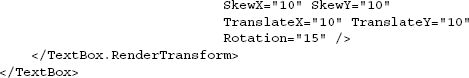
To rotate, you'd need to plug in the sine and cosine values into M11, M12, M21, and M22. For example, to rotate by 15 degrees, the matrix would look like this:
1 | 2 | 3 | |
|---|---|---|---|
1 | M11 (Cos(15)) | M12 (Sin(15)) | 0 |
2 | M21 (-Sin(15)) | M22 (Cos(15)) | 0 |
3 | OffsetX (0.0) | OffsetY (0.0) | 1 |
Listing 6.16 shows the hard-coded values for a rotation of 15 degrees plus an offset of 100 pixels in the x-axis and 20 pixels on the y-axis.
One nice thing you can do with MatrixTransform is perform multiple transformations in a single step. Prior to the introduction of CompositeTransform, this was the only way to achieve that operation. If you need to control the order of those transformations, you can multiply together two or more matrices.
Render transforms are a powerful way to manipulate the display of your elements. You'll find transforms essential in animation, both to provide gross-level movement and to provide more subtle effects such as a pop when you click a button. They're also helpful in that they don't force a layout pass to happen, as would be the case if you animated something like the actual Width and Height of the element.
One thing none of the transformations can do, though, is a nonaffine transform such as a perspective effect. For that, you need to turn to 3D projection.
3D projection transforms, introduced in Silverlight 3, provide a way to do nonaffine (perspective and distortion) transforms on an object. The UI elements to which the transforms are applied remain active and available, just as with render transforms.
Like render transforms, projections don't affect layout; they're a render-time transformation that exists outside the layout pass.
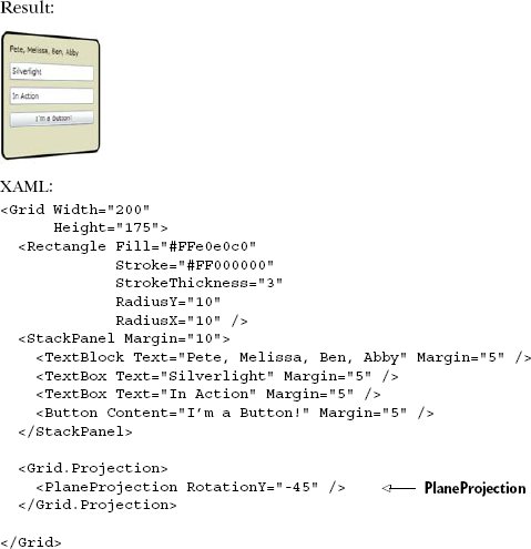
We'll start with the PlaneProjection, the easiest and most popular of the two types of projections, and then look at the somewhat more obscure, but extremely powerful, Matrix3dProjection.
Plane projection (System.Windows.Media.PlaneProjection), introduced in Silverlight 3, was one of the most anticipated features to make it into the product. At the time of Silverlight 3, the CoverFlow effect from iTunes was all the rage. You could simulate it using skew transforms and stitching of images but the result was never quite right.
PlaneProjection has several key properties, as described in table 6.3. You may wonder why it exposes denormalized properties instead of three 3D point structures. The reason is binding and animation: by providing the individual properties as DependencyProperty properties, they can be used in binding and animation.
Table 6.3. PlaneProjection properties
Property | Description |
|---|---|
| These represent the overall rotation of the object, in degrees for each axis. |
| These represent the object-oriented center of rotation. 0.5, 0.5 is the center of the plane on that axis and is the default value. |
| These values translate the object along the specified axis, providing for motion in 3D space. The values are relative to the screen. So the y-axis will always be vertical and point up, and the x-axis will always be horizontal and point to the right. |
| Unlike the |
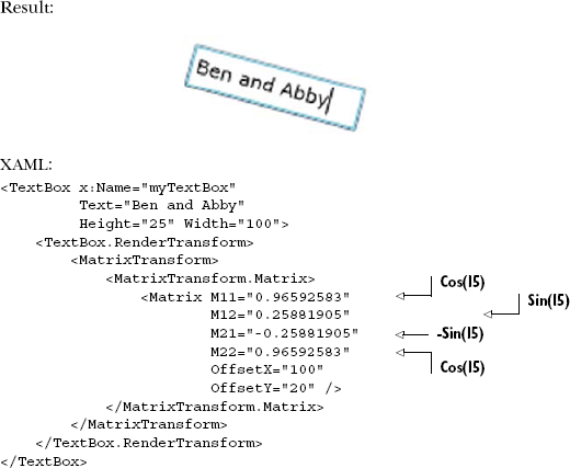
For each of the properties, the screen axes are defined as shown in figure 6.7. Positive y is vertical top, positive x is horizontal right. Silverlight, at least in the case of the PlaneProjection, follows a right-hand coordinate system, so positive z is closer to you, and negative z is further "into" the screen.
Both the PlaneProjection and its related Matrix3dProjection are assigned to an object via its Projection property.
Listing 6.17 shows a simple PlaneProjection applied to a set of UI elements. In this case, the projection is on the y-axis, giving you that classic CoverFlow look but applied to live input controls.
As with 2D affine transforms, Silverlight also supports a lower-level Matrix transform for 3D. The class is named System.Windows.Media.Matrix3dProjection.
Due to the complexity of explaining 4×4 nonaffine matrices, and the relatively small subset of readers who'll be interested in that, we'll leave the fine details of 3D matrix projections out. But let's look at a simple code example to get you started.
Listing 6.18 shows how to do something that isn't provided just by 3D rotation on an axis. This combines skew effects with rotation to come up with something that can only be described as interesting.
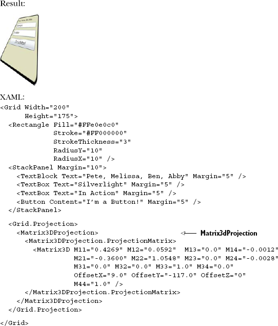
Matrix3dProjection is something you may only ever use once but, for that one time, it'll be exactly what you need to solve a specific problem. The sky's the limit when it comes to 3D transformations (actually 2.5D because Silverlight doesn't yet have a true 3D engine) for your Silverlight applications.
One thing you may have noticed with the projection transforms is that they add some fuzziness to the elements when they render. That's because the render transforms operate on frame-by-frame bitmap representations of the objects. That makes them extremely performant, but also causes them to have a slight degradation in quality, especially when you do something such as an extreme z scale, as in the Matrix3dProjection example.
Silverlight provides two easy-to-use but powerful ways to transform objects in 3D space: PlaneProjection and Matrix3dProjection. PlaneProjection, in particular, will find its way into a lot of your applications. In fact, if you develop for Silverlight for the Windows Phone, you'll find the PlaneProjection indispensible for providing the expected page flip UI transitions.
In the last two examples, I used a combination of Grids and StackPanels to hold the elements I was transforming. Both of these are types of Panels and will be something you use over and over again in your own applications.
The basis for all onscreen elements is the FrameworkElement and UIElement pair. The two of them define the majority of the commonly used properties and methods for other elements. In addition, they define the abstract methods for measuring and layout, the core of the layout system.
Framework elements, UI elements, and panels are the fundamental players in the layout system. Layout in Silverlight is so flexible because so much of the measurement and layout are delegated to the elements themselves. An understanding of the layout system is important for both performance and flexibility reasons and is a must should you wish to create your own panels.
The layout system is a major part of a much larger rendering system. The rendering system in Silverlight does a good job at optimizing the elements onscreen for efficient rendering, but also provides appropriate places where you can tune that process to fit your own applications. Silverlight enables you to cache elements, for example, and even to control whether cached elements are cached to hardware surfaces on a compatible video card.
Render transformations allow us to transform the location, rotation, skew, or size of any visible element without incurring the performance hit of a layout system pass. For that reason, they're perfectly suited to animation and more performance-hungry uses. What render transformations lack is support for nonaffine or perspective transforms.
The two types of 3D projections pick up where render transforms leave off, and provide support for nonaffine, perspective, and distorting 3D transformations. The PlaneProjection is the easiest to use and suitable for most types of basic projection work. The Matrix3dProjection is a little harder to use but is extremely powerful. If you want to do basic CoverFlow-style work, PlaneProjection is for you. If you want to do a more immersive 3D experience with floating panels zipping past you and appearing off in the distance, you're probably looking at the Matrix3dProjection class and some of its helper libraries on www.codeplex.com.
With framework and UI elements, the rendering and layout system, transformations, and projections under our belt, we're ready to move on to the fundamentals of working with layout panels. Panels form the root elements for most of our interfaces and are the main elements responsible for layout in Silverlight.