
In WebGL, we make use of the vertex and fragment shaders to create a lighting model for our scene. Shaders allow us to define a mathematical model that governs how our scene is lit. We will study different algorithms and see examples about their implementation.
A basic knowledge of linear algebra will be really useful to help you understand the contents of this chapter. We will use glMatrix, a JavaScript library that handles most of the vector and matrix operation, so you do not need to worry about the details. Nonetheless, it is paramount to have a conceptual understanding of the linear algebra operations that we will discuss.
In this chapter, we will:
- Learn about light sources, normals, and materials
- Learn the difference between shading and lighting
- Use the Goraud and Phong shading methods, and the Lambertian and Phong lighting models
- Define and use uniforms, attributes, and varyings
- Work with ESSL, the shading language for WebGL
- Discuss relevant WebGL API methods that relate to shaders
- Continue our analysis of WebGL as a state machine and describe the attributes relevant to shaders that can be set and retrieved from the state machine
In the real world, we see objects because they reflect light. Any object will reflect light depending on the position and relative distance to the light source; the orientation of its surface, which is represented by normal vectors and the material of the object which determines how much light is reflected. In this chapter, we will learn how to combine these three elements in WebGL to model different illumination schemes.
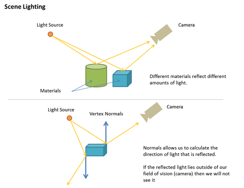
Light sources can be positional or directional. A light source is called positional when its location will affect how the scene is lit. For instance, a lamp inside a room falls under this category. Objects far from the lamp will receive very little light and they will appear obscure. In contrast, directional lights refer to lights that produce the same result independent from their position. For example, the light of the sun will illuminate all the objects in a terrestrial scene, regardless of their distance from the sun.
A positional light is modeled by a point in space, while a directional light is modeled with a vector that indicates its direction. It is common to use a normalized vector for this purpose, given that this simplifies mathematical operations.
Normals are vectors that are perpendicular to the surface that we want to illuminate. Normals represent the orientation of the surface and therefore they are critical to model the interaction between a light source and the object. Each vertex has an associated normal vector.
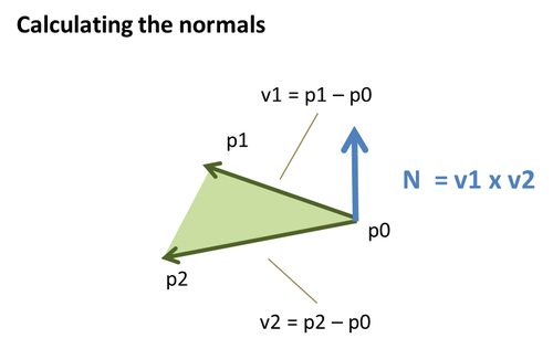
We make use of a cross product for calculating normals.
Note
Cross Product:
By definition, the cross product of vectors A and B will be perpendicular to both vectors A and B.
Let's break this down. If we have the triangle conformed by vertices p0, p1, and p2, then we can define the vector v1 as p2-p1 and the vector v2 as p0-p1. Then the normal is obtained by calculating the cross product v1 x v2. Graphically, this procedure looks something like the following:
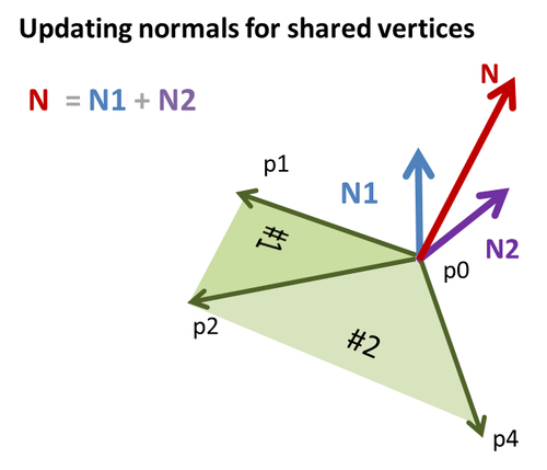
Then we repeat the same calculation for each vertex on each triangle. But, what about the vertices that are shared by more than one triangle? The answer is that each shared vertex normal will receive a contribution from each of the triangles in which the vertex appears.
For example, say that the vertex p1 is being shared by triangles #1 and #2, and we have already calculated the normals for the vertices of triangle #1. Then, we need to update the p1 normal by adding up the calculated normal for p1 on triangle #2. This is a vector sum. Graphically, this looks similar to the following:
Similar to lights, normals are usually normalized to facilitate mathematical operations.
The material of an object in WebGL can be modeled by several parameters, including its color and its texture. Material colors are usually modeled as triplets in the RGB space (Red, Green, Blue). Textures, on the other hand, correspond to images that are mapped to the surface of the object. This process is usually called Texture Mapping. We will see how to perform texture mapping in Chapter 7, Textures.