
Objects in a WebGL scene go through different transformations before we can see them on our screen. Each transformation is encoded by a 4x4 matrix, as we will see later. How do we multiply vertices that have three components (x,y,z) by a 4x4 matrix? The short answer is that we need to augment the cardinality of our tuples by one dimension. Each vertex then will have a fourth component called the homogenous coordinate. Let's see what they are and why they are useful.
Homogeneous coordinates are a key component of any computer graphics program. Thanks to them, it is possible to represent affine transformations (rotation, scaling, shear, and translation) and projective transformations as 4x4 matrices.
In Homogeneous coordinates, vertices have four components: x, y, z, and w. The first three components are the vertex coordinates in Euclidian Space. The fourth is the perspective component. The 4-tuple (x,y,z,w) take us to a new space: The Projective Space.
Homogeneous coordinates make possible to solve a system of linear equations where each equation represents a line that is parallel with all the others in the system. Let's remember here that in Euclidian Space, a system like that does not have solutions, because there are not intersections. However, in Projective Space, this system has a solution — the lines will intersect at infinite. This fact is represented by the perspective component having a value of zero. A good physical analogy of this idea is the image of train tracks: parallel lines that touch in the vanishing point when you look at them.
It is easy to convert from Homogeneous coordinates to non-homogeneous, old-fashioned, Euclidean coordinates. All you need to do is divide the coordinate by w:
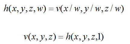
Consequently, if we want to go from Euclidian to Projective space, we just add the fourth component w and make it 1.
As a matter of fact, this is what we have been doing so far! Let's go back to one of the shaders we discussed in the last chapter: the Phong vertex shader. The code looks like the following:
attribute vec3 aVertexPosition;
attribute vec3 aVertexNormal;
uniform mat4 uMVMatrix;
uniform mat4 uPMatrix;
uniform mat4 uNMatrix;
varying vec3 vNormal;
varying vec3 vEyeVec;
void main(void) {
//Transformed vertex position
vec4 vertex = uMVMatrix * vec4(aVertexPosition, 1.0);
//Transformed normal position
vNormal = vec3(uNMatrix * vec4(aVertexNormal, 0.0));
//Vector Eye
vEyeVec = -vec3(vertex.xyz);
//Final vertex position
gl_Position = uPMatrix * uMVMatrix * vec4(aVertexPosition, 1.0);
}
Please notice that for the aVertexPosition attribute, which contains a vertex of our geometry, we create a 4-tuple from the 3-tuple that we receive. We do this with the ESSL construct vec4(). ESSL knows that aVertexPosition is a vec3 and therefore we only need the fourth component to create a vec4.
Note
To pass from Homogeneous coordinates to Euclidean coordinates, we divide by w
To pass from Euclidean coordinates to Homogeneous coordinates, we add w =1
Homogeneous coordinates with w = 0 represent a point at infinity
There is one more thing you should know about Homogeneous coordinates — while vertices have a Homogeneous coordinate w = 1, vectors have a Homogeneous coordinate w = 0. This is the reason why, in the Phong vertex shader, the line that processes the normals looks like this:
vNormal = vec3(uNMatrix * vec4(aVertexNormal, 0.0));
To code vertex transformations, we will be using Homogeneous coordinates unless indicated otherwise. Now let's see the different transformations that our geometry undergoes to be displayed on screen.
We start our analysis from the object coordinate system. It is in this space where vertex coordinates are specified. Then if we want to translate or move objects around, we use a matrix that encodes these transformations. This matrix is known as the model matrix. Once we multiply the vertices of our object by the model matrix, we will obtain new vertex coordinates. These new vertices will determine the position of the object in our 3D world.
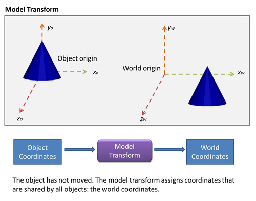
While in object coordinates, each object is free to define where its origin is and then specify where its vertices are with respect to this origin, in world coordinates, the origin is shared by all the objects. World coordinates allow us to know where objects are located with respect to each other. It is with the model transform that we determine where the objects are in the 3D world.
The next transformation, the view transform, shifts the origin of the coordinate system to the view origin. The view origin is where our eye or camera is located with respect to the world origin. In other words, the view transform switches world coordinates by view coordinates. This transformation is encoded in the view matrix. We multiply this matrix by the vertex coordinates obtained by the model transform. The result of this operation is a new set of vertex coordinates whose origin is the view origin. It is in this coordinate system that our camera is going to operate. We will go back to this later in the chapter.

The next operation is called the projection transform. This operation determines how much of the view space will be rendered and how it will be mapped onto the computer screen. This region is known as the frustum and it is defined by six planes (near, far, top, bottom, right, and left planes), as shown in the following diagram:
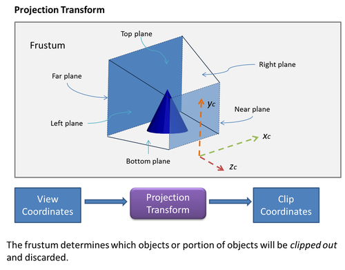
These six planes are encoded in the Perspective matrix. Any vertices lying outside of the frustum after applying the transformation are clipped out and discarded from further processing. Therefore, the frustum defines, and the projection matrix that encodes the frustum produces, clipping coordinates.
The shape and extent of the frustum determines the type of projection from the 3D viewing space to the 2D screen. If the far and near planes have the same dimensions, then the frustum will determine an orthographic projection. Otherwise, it will be a perspective projection, as shown in the following diagram:

Up to this point, we are still working with Homogeneous coordinates, so the clipping coordinates have four components: x, y, z, and w. The clipping is done by comparing the x, y, and z components against the Homogeneous coordinate w. If any of them is more than, +w, or less than, -w , then that vertex lies outside the frustum and is discarded.
Once it is determined how much of the viewing space will be rendered, the frustum is mapped into the near plane in order to produce a 2D image. The near plane is what is going to be rendered on your computer screen.
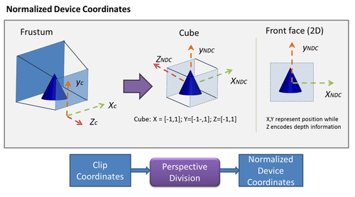
Different operative systems and displaying devices can have mechanisms to represent 2D information on screen. To provide robustness for all possible cases, WebGL (also in OpenGL ES) provides an intermediate coordinate system that is independent from any specific hardware. This space is known as the Normalized Device Coordinates (NDC).
Normalized device coordinates are obtained by dividing the clipping coordinates by the w component. This is the reason why this step is known as perspective division. Also, please remember that when you divide by the Homogeneous coordinate, we go from projective space (4-components) to Euclidean space (3-components), so NDC only has three components. In the NDC space, the x and y coordinates represent the location of your vertices on a normalized 2D screen, while the z-coordinate encodes depth information, which is the relative location of the objects with respect to the near and far planes. Though, at this point, we are working on a 2D screen, we still keep the depth information. This will allow WebGL to determine later how to display overlapping objects based on their distance to the near plane. When using normalized device coordinates, the depth is encoded in the z-component.
The perspective division transforms the viewing frustum into a cube centered in the origin with minimum coordinates [-1,-1,-1] and maximum coordinates [1,1,1]. Also, the direction of the z-axis is inverted, as shown in the following figure:
Finally, NDCs are mapped to viewport coordinates. This step maps these coordinates to the available space in your screen. In WebGL, this space is provided by the HTML5 canvas, as shown in the following figure:

Unlike the previous cases, the viewport transform is not generated by a matrix transformation. In this case, we use the WebGL viewport function. We will learn more about this function later in the chapter. Now it is time to see what happens to normals.