Basic Hyper-V Networking
Networking is a huge subject in Windows Server 2012 Hyper-V. We are going to start with the basics, moving through some new features that can be difficult to understand at first, and building your knowledge up in layers, before you go on to the more-complex topics in Chapter 5, “Cloud Computing,” Chapter 7, “Using File Servers,” and Chapter 8, “Building Hyper-V Clusters.” We recommend that you read through each subject, even if you are experienced in networking or Hyper-V. At the very least, this will serve as a refresher, but you might find that you learn something that will be important to later topics.
In this section, you will look at the basics of Hyper-V networking that are required to connect your virtual machines to a network. You will be introduced to the new Hyper-V virtual switch before looking at the greatly anticipated NIC teaming feature.
Using the Hyper-V Extensible Virtual Switch
In the past, Hyper-V had a relatively simple virtual device in the host called a virtual network to connect virtual machines to networks. The virtual network has been replaced by something much more exciting (for nerds who get excited by this sort of thing) and powerful: the virtual switch. This is a central piece in Microsoft’s Windows Server 2012 cloud operating system strategy. Users of previous versions of Hyper-V will still create the new virtual switch the same way that they created the virtual network, and the same types are still used. However, it won’t be long until the power of the switch becomes evident.
Understanding the Virtual Network Interface Controller
In Chapter 3, “Managing Virtual Machines,” you saw that virtual machines could have one or more virtual network interface controllers (NICs) in their configuration to allow the virtual machines to connect to a network. Virtual NICs are not confined to just virtual machines; the management OS can also have virtual NICs. This might be a little difficult to understand at first. Where does this NIC reside? What does it connect to? It resides in the management OS, and it appears in Network Connections just like a physical NIC. Like every virtual NIC in virtual machines, the management OS virtual NICs connect to a virtual switch. You will see a few ways to create and use virtual NICs as you proceed through this chapter.
Introducing the Virtual Switch
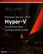
The virtual switch performs the same basic task as a physical server. A physical switch connects the NICs of physical servers to a network, providing each connection with its own isolated source-to-destination connection. A network administrator might route that network or might make it an isolated network. There are three kinds of virtual switch, and each kind will connect the virtual NICs of virtual machines to a different kind of network:
Figure 4-1 An external virtual switch
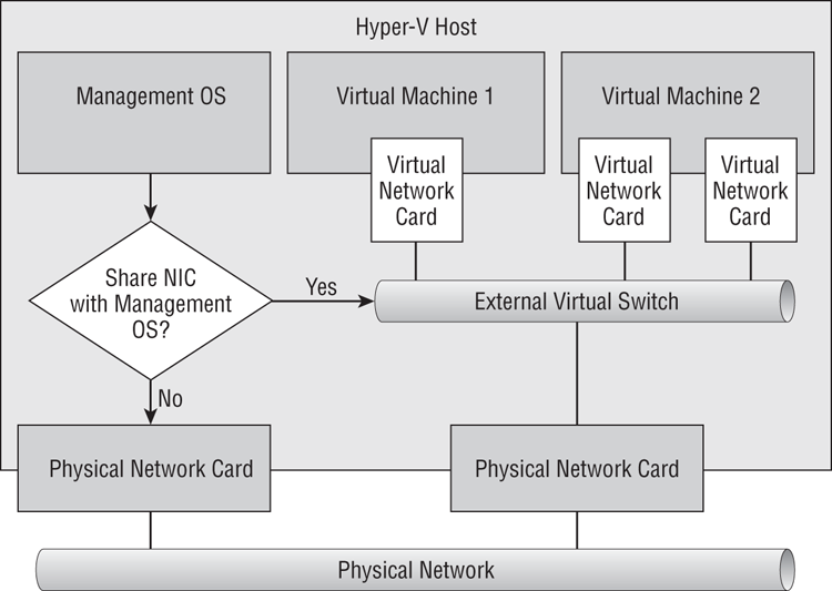
Figure 4-2 A private virtual switch
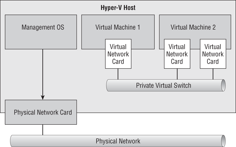
Figure 4-3 Internal virtual switch
Creating Virtual Switches
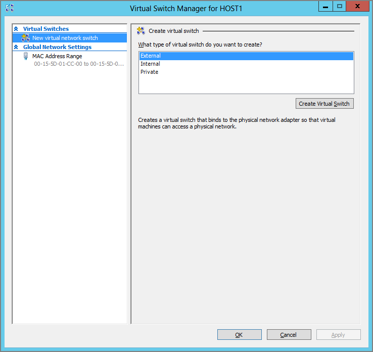
If you want to create a virtual switch for basic functionality, you can do this in the Hyper-V Manager console. Under Actions, you will see an option for Virtual Switch Manager. Clicking that option opens the Virtual Switch Manager for the selected host, as shown in Figure 4-4.
Figure 4-4 The Virtual Switch Manager
To create a new virtual switch, you do the following:
Figure 4-5 Configure the new virtual switch.
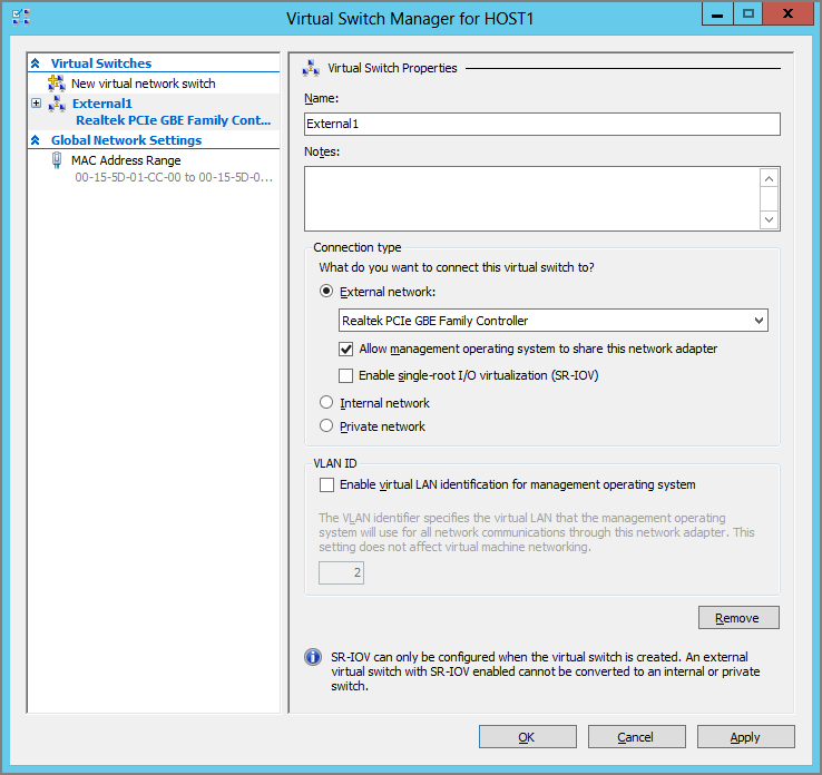
The options available depend on the type of virtual switch that you have decided to create.
You can choose External Network (with further options), Internal Network, or Private Network to change the type of virtual switch that you want to create. The choice of External Network has one configuration requirement and offers two options:
- From the options in the drop-down list box, you choose the physical network adapter that you want to connect the virtual switch to. Only connections that are unused will be available. Unfortunately, this does not give you the human-friendly name of the network connection; it uses the actual device name. You can retrieve the device name of the desired network connection by opening Network Connections and using the details view or by running the Get-NetAdapter | Format-Table -Autosize PowerShell cmdlets.
- The Allow Management Operating System To Share This Network Adapter option is selected by default if you have chosen to create an External Network. You should clear this check box if you want to physically isolate the management OS networking on a different network. In the past, Hyper-V engineers typically wanted to isolate the management OS from virtual machine traffic and so have cleared this option.
Single-Root I/O Virtualization (SR-IOV) is a new feature in Windows Server 2012 Hyper-V that allows virtual NICs to run with less latency than usual if you have the required hardware. You’ll learn more about this feature later in the chapter. It is not selected by default and should be selected only if you are absolutely certain that you do want to enable SR-IOV; this will require some understanding of this advanced feature. Note that this option can be selected only when you create the switch, and it cannot be changed without deleting and re-creating the switch.
If you choose either of the following configurations for the virtual switch, a management OS virtual NIC will be created and connected to the virtual switch:
- An external virtual switch that is shared with the management OS
- An internal virtual switch
If you did choose one of these configurations, you can configure the management OS virtual network with a VLAN ID. This will isolate the traffic at the virtual and physical switch level, and will require some work by the physical network administrators to trunk the connected switch ports to support VLANs. Choosing this option does not place the virtual switch on the VLAN; it places only the management OS virtual NIC on that VLAN.
When you create a virtual switch, you might get a warning that the creation process may disconnect anyone using services on the management OS. For example, creating an external virtual switch via Remote Desktop will disconnect your session if you select the Remote Desktop NIC to be the connection point for an external switch.
You can return to Virtual Switch Manager to modify a switch (except for the SR-IOV setting) or to even delete it.
You can use New-VMSwitch to create a virtual switch, which is disconnected from the management OS by using PowerShell:
New-VMSwitch “External1” -NetAdapterName “Ethernet” -AllowManagementOS 0That snippet creates an external virtual switch by default. You can change the type by adding the -SwitchType flag and choosing from External, Internal, or Private:
New-VMSwitch “Internal1” -SwitchType InternalThis creates a new virtual switch that virtual machines can be connected to. The management OS will also get a new virtual NIC called vEthernet (Internal1) that will require an IP configuration. Here is how you can configure IPv4 for this virtual NIC:
NewNetIPAddress -InterfaceAlias “vEthernet (Internal1)” -IPAddress 10.0.15.1 -PrefixLength 24 -Default Gateway 10.0.15.254Set-DnsClientServerAddress -InterfaceAlias "vEthernet (Internal1)" -ServerAddresses 10.0.15.21, 10.0.15.22Get-VMSwitch can be used to retrieve a virtual switch. Set-VMSwitch can be used to configure a virtual switch. For example, you can quickly reconfigure a virtual switch to use a different physical connection by using this line of PowerShell:
Set-VMSwitch “External1” -NetAdapterName “Ethernet 3”You could always change your mind about not sharing the virtual switch’s network connection with the management OS:
Set-VMSwitch "External1" AllowManagementOS 1Here’s an example of the power of PowerShell; you can quickly move all the virtual NICs that are connected to one virtual switch to another virtual switch in one line of code instead of dozens, hundreds, or even thousands of mouse clicks:
Get-VMNetworkAdapter * | Where-Object {$_.SwitchName -EQ “Private1”} | `
Connect-VMNetworkAdapter -SwitchName “External1”
The first piece of the code retrieves all the virtual NICs on the host, before filtering them down to just the ones connected to the Private1 virtual switch. The remaining virtual NICs are then changed so they connect to the External1 virtual switch instead.
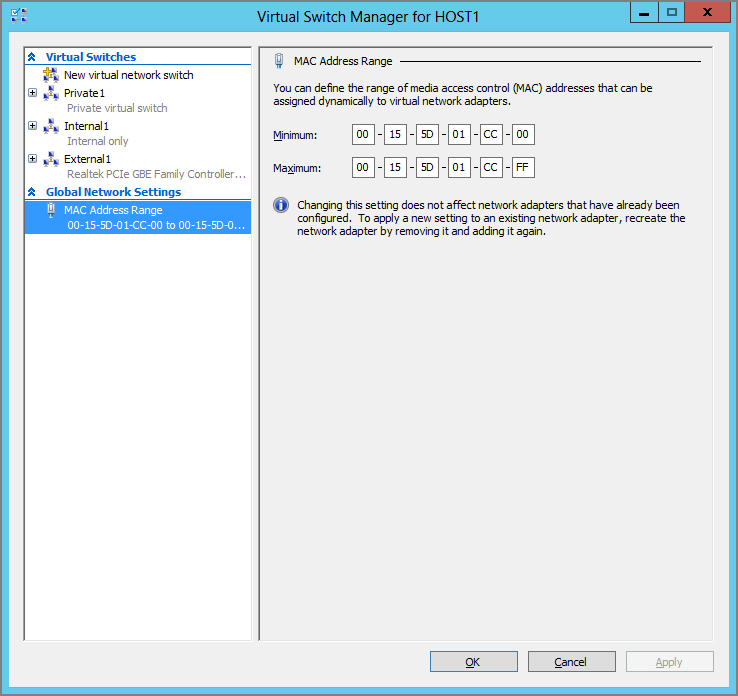
By default, all newly created virtual NICs have a dynamically assigned MAC or Ethernet address. Each MAC address is assigned from a pool of addresses that are defined in the Virtual Switch Manager screen, as you can see in Figure 4-6. You can alter this range of MAC addresses if required by the network administrator. Note that this will not affect the in-use MAC addresses of any virtual NIC that is currently in operation on the host at the time of the change.
Figure 4-6 The MAC address range for this host
You have learned the basics of configuring a virtual switch. Now it’s time to see why it’s called the extensible virtual switch.
Adding Virtual Switch Extensibility
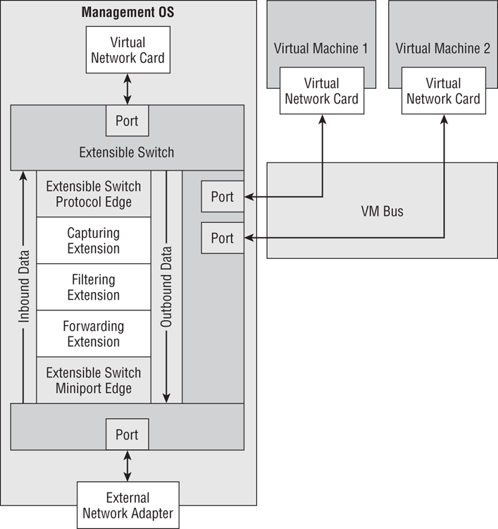
By itself, the Hyper-V virtual switch is a powerful network appliance, but it can be given more functionality by installing third-party extensions. Each of these extensions adds functionality to the Hyper-V virtual switch instead of replacing it. The extensions are certified Network Driver Interface Specification (NDIS) filter drivers or Windows Filtering Platform (WFP) filters/drivers.
As you can see in Figure 4-7, three types of extensions can be added to a Hyper-V extensible virtual switch:
Figure 4-7 The architecture of the Hyper-V extensible virtual switch
You will have to refer to the vendors of the third-party extensions for specific guidance and instructions for their solutions. However, you can perform the following operations in the Virtual Switch Manager:
- Enable and disable extensions.
- Reorder extensions within their own type. For example, you cannot make a monitoring extension see inbound data before a filtering extension sees it.
To perform these operations on a virtual switch, you follow these steps:
Here you can do the following:
- Select (to enable) or deselect (to disable) the check boxes beside an extension.
- Select an extension and click Move Up or Move Down to reorder the extension within its own extension type.
- Select an extension to see its description under Details for Selected Extensions.
The small amount of text in this chapter on the extensibility of the Hyper-V virtual switch might mislead you on the importance of this functionality. The features, security, flexibility, and the extension of SDN into the physical network make the extensibility of the virtual switch extremely important. In fact, it’s one of the headline-making features of Windows Server 2012 that make it a true cloud operating system and is described extensively in Chapter 5.
Supporting VLANs
The virtual LAN (VLAN) is a method of dividing a physical LAN into multiple subnets for a number of reasons. VLANs can create more address space, control broadcast domains, and isolate traffic. They have been used (many say misused) to create security boundaries that are routed and filtered by firewalls. Each VLAN has an ID, or tag, that is used to dynamically associate a device with that VLAN so it can communicate only on the VLAN.
We can support VLANs in Hyper-V in many ways, some of which you will read about in Chapter 5. You have already seen how to associate a management OS virtual NIC with a VLAN when the management OS shares a physical connection with an external virtual switch. We will cover additional basic VLAN solutions in this chapter.
The typical request is to have a single virtual switch that can support many virtual machines connected to many VLANs. In reality, what is being requested is to have many virtual NICs connected to many VLANs; you’ll soon see why.
Configuring Physical Isolation of VLANs
A very crude approach is to have one physical NIC for every required VLAN. You can see this in Figure 4-8. In this example, you have two VLANs, 101 and 102. A port is configured on the switch for each VLAN. Each port is connected to a physical NIC on the host. An external virtual switch is created for each of the VLANs/physical NICs. And the virtual NICs of the virtual machines are connected to the associated VLANs/virtual switches.
Figure 4-8 Physical isolation for each VLAN
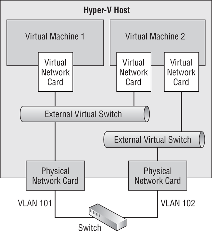
This is not a good solution. It might be OK for a lab or the smallest of installations, but it is not flexible, it is not scalable, and it will require lots of NICs if you have lots of VLANs (and double the number if you require NIC teaming).
The only scalable approach to VLANs is to deal with them at the software layer. There are many ways to do that, and the next two options are some of those that you can use.
Assigning VLAN IDs to Virtual NICs
With this approach, you create a single external virtual switch and then configure the VLAN ID of each virtual NIC to link it to the required VLAN. The benefits are as follows:
- The solution is software based, so it can be automated or orchestrated for self-service cloud computing.
- Scalability is not an issue because the approach is software based.
- The solution requires very little infrastructure configuration.
- The solution is secure because only the virtualization administrator can configure the VLAN ID.
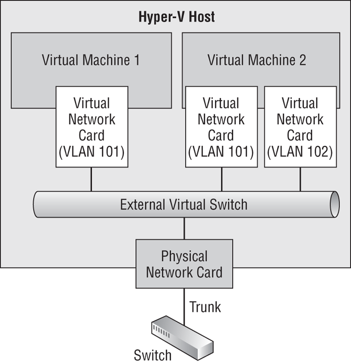
Figure 4-9 shows the solution. The network administrator creates the required VLANs and sets up a trunk port in the switch. The physical NIC in the host is connected to the trunk port. An external virtual switch is created, as usual, and connected to the physical NIC. Virtual machines are created, as usual, and their NICs are connected to the single virtual switch, even though lots of virtual machines are going to be connected to lots of VLANs. The trick here is that the virtualization administrator (or the orchestration software) assigns each virtual NIC to a specific VLAN. The trunk is passed into the virtual switch, and this allows the virtual NIC to be bound to and communicate on the assigned VLAN and only the assigned VLAN.
Note that if you trunk the switch port, every virtual NIC that is assigned to the switch port must be assigned a VLAN ID to communicate.
Figure 4-9 Using virtual NICs to assign VLAN IDs
You can configure the VLAN ID of a virtual NIC as follows:
You can change virtual NIC VLANs while a virtual machine is running. You can also change the VLAN ID of a virtual network by using PowerShell:
Set-VMNetworkAdapterVLAN -VMName “Virtual Machine 1” -Access -VLANID 101This is a simple scenario; Virtual Machine 1 has only a single virtual NIC, so we can just target the virtual machine to assign the VLAN to that virtual NIC. The virtual NIC is configured in access mode (a simple assignment) to tag only traffic for VLAN 101.
What if we had to assign a VLAN to a virtual machine with more than one virtual NIC, such as Virtual Machine 2, previously seen in Figure 4-9? Set-VMNetworkAdapter allows us to specify the name of a specific virtual NIC. That’s a problem, because the name of each virtual NIC in the virtual machine settings is the rather anonymous Network Adapter, no matter how many virtual NICs the virtual machine has. So which one do you configure? First, you could run the following to get the virtual NICs of the virtual machine:
$NICS = Get-VMNetworkAdapter -VMName “Virtual Machine 2”The results of the query are stored as an array in the $NICS variable. An array is a programming construct that contains more than one value. Each result is stored in the array and is indexed from 0 to N. In this case, Virtual Machine 2 has two virtual NICs. That’s two entries in the array, with the first being indexed as [0] and the second indexed as [1]. We know that we want to configure the second virtual NIC to be in VLAN 102:
Set-VMNetworkAdapterVLAN -VMName “Virtual Machine 2” -VMNetworkAdapter `
$NICS[1].Name -Access -VLANID 102
If you want, you can flatten the entire solution down to a single, difficult-to-read line, in the traditional PowerShell way:
Set-VMNetworkAdapterVLAN -VMName “Virtual Machine 2” -VMNetworkAdapter `
{Get-VMNetworkAdapter -VMName “Virtual Machine 2”}[1].Name -Access `
-VLANID 102
Using a Virtual Switch VLAN Trunk
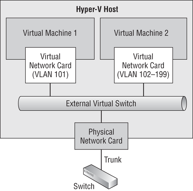
Another approach to dealing with VLANs is to simply pass the VLAN trunk up through the virtual switch port and into the virtual NIC of the virtual machine. In the example in Figure 4-10, the virtual NIC of Virtual Machine 1 will be configured in access mode to connect to a single VLAN. The virtual NIC of Virtual Machine 2 will be configured in trunk mode to allow VLANs that are specified by the Hyper-V or cloud administrator.
Figure 4-10 Trunk mode for a virtual NIC
There is a certain level of trust being placed on the administrator of the guest operating system in a virtual machine that is granted trunk mode access to VLANs. The guest OS administrator should know the following:
- How to configure VLANs in the guest OS
- What traffic to send over what VLAN
- Not to misuse this delegated right
There is a certain amount of control that the Hyper-V or cloud administrator retains. Only specified VLANs will be trunked, so the guest OS administrator can successfully tag traffic for only the delegated VLANs.
Creating a trunked virtual switch port through to a virtual NIC is an advanced feature that should be rarely used, and it does not have a place in the GUI. You can configure trunk mode to the virtual NIC by using PowerShell only:
Set-VMNetworkAdapterVLAN -VMName “Virtual Machine 2” -Trunk -AllowedVLANList `
102-199 -NativeVLANID 102
The cmdlet has configured the virtual switch’s port for Virtual Machine 2 to be trunked for VLANs 102 to 199. A required safety measure is to specify a fallback VLAN in case the guest OS administrator fails to set VLAN IDs within the guest OS. In this example, the fallback VLAN is 102.
In this example, only one virtual NIC is in the virtual machine; you can target specific virtual NICs by using the method that was shown in the previous section. You can query the results of your VLAN engineering as follows:
PS C:> Get-VMNetworkAdapterVLAN
VMName                VMNetworkAdapterName Mode   VlanList
------                -------------------- ----   --------
VirtualMachine1       Network Adapter   Access  101
VirtualMachine2       Network Adapter   Trunk  102,102-199
This is where we’re going to leave VLANs for now, but we will make a quick return during the coverage of NIC teaming.
Supporting NIC Teaming
If you ever delivered presentations on or sold Hyper-V implementations before Windows Server 2012, you were guaranteed one question: is there built-in NIC teaming? Finally, the answer is yes—and it is completely supported for Hyper-V and Failover Clustering.
NIC teaming, also known as NIC bonding or load balancing and failover (LBFO) for NICs, was not supported by Microsoft in the past. Third parties such as server manufacturers offered NIC teaming software. But this software made huge changes to how Windows and Hyper-V networking worked, and Microsoft never supported these solutions in any way on their operating systems or for virtualization. Microsoft Support has a policy that could require customers to re-create a problem without third-party NIC teaming to prove that the add-on is not the cause of a problem.
But now Windows Server 2012 includes a NIC teaming solution. We no longer need to use third-party NIC teaming software, although hardware vendors might continue to offer it with the promise of additional features, albeit with the price of losing support from Microsoft.
If you have used NIC teaming in the past, you might be tempted to skip ahead in the chapter. Instead, we urge you to read this section of the book because it might prevent you from making some mistakes that are caused by common misunderstandings of how NIC teaming works. You will also require the knowledge in this section when you start to look at enabling Receive-Side Scaling (RSS - for SMB Multichannel) and Dynamic Virtual Machine Queue (DVMQ).
Understanding NIC Teaming
In NIC teaming, we group NICs together to act as a single unit, much as we use RAID to group disks. This results in the following:
Figure 4-11 NIC teaming with highly available networking
Together, these two functions are known as LBFO. Typically, NIC teaming might add more functionality, support VLANs, and require some configuration depending on the environment and intended usage.
Using Windows Sever 2012 NIC Teaming
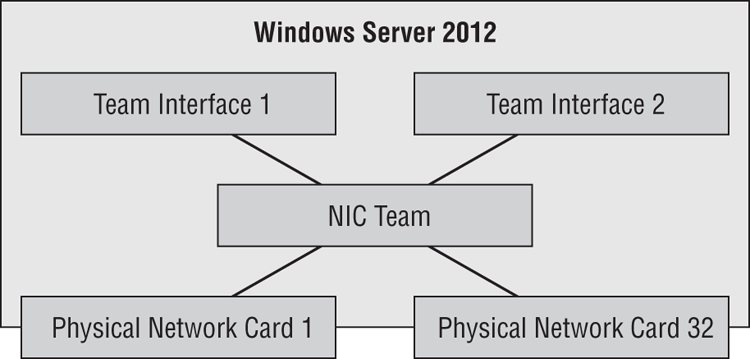
The NIC teaming in Windows Server 2012 gives us LBFO as you would expect. You can see the basic concept of a NIC team in Figure 4-12. A Windows Server 2012 NIC team is made up of 1 to 32 physical NICs, also known as team members. The interesting thing is that these NICs can be not only any model, but also from any manufacturer. The only requirement is that the team member NICs have passed the Windows Hardware Quality Labs (WHQL) test—that is, they are on the Windows Server 2012 Hardware Compatibility List (HCL), which can be found at www.windowsservercatalog.com. The team members can even be of different speeds, but this is not recommended because the team will run at the lowest common denominator speed.
The ability to combine NICs from different manufacturers offers another kind of fault tolerance. It is not unheard of for there to be a NIC driver or firmware that is unstable. A true mission-critical environment, such as air traffic control or a stock market, might combine NICs from two manufacturers just in case one driver or firmware fails. If that happens, the other NIC brand or model should continue to operate (if there wasn’t a blue screen of death), and the services on that server would continue to be available.
A NIC team has at least one team interface, also known as a team NIC or tNIC. Each team interface appears in Network Connections. You will configure the protocol settings of the team interface rather than those of the team members. The team members become physical communication channels for the team interfaces.
Figure 4-12 Components of a NIC team
There are some important points regarding team interfaces:
NIC teaming enables us to give our hosts and virtual machines higher levels of availability in case of an outage. We can use one or more NIC teams for the management OS and associated network connections (possibly using additional team interfaces), and we can use another NIC team to connect the external virtual switch to the physical network.
Configuring NIC Teams
If you asked administrators how they configured the settings of their NIC teams in the past, most of them probably would (if they were honest) say that they just took the default options; the NIC team just worked. Some might even admit that they looked at the list of options, figured that everything was working anyway, and left the settings as is—it is best not to mess with these things.
The reality is that their success resulted from a lot of blind luck. It is only when you start to place a massive load (the kind that dense virtualization can create) or you purchase 10 GbE networking and want to see how much of it you can consume, that you soon realize that there must be more to NIC teaming, because the default options are not giving you the results that you were expecting. And there is more to it than accepting the defaults:
- What sort of switching environment do you have? That affects how the switch ports that are connected to the team members will know that this is a team.
- What kind of workload are you putting on the NIC team? This will determine how outbound traffic is distributed across the team and how inbound traffic is handled by the switches.
- How will your NIC team configuration impact the usage of advanced NIC hardware features?
The first choice you have to make is related to the kinds of switching in the physical network that the NIC team is connected to:
The second choice you have to make regarding the configuration of a NIC team is how to distribute the traffic across the team. There are two options:
- 4-tuple hash: This method hashes TCP/UDP ports and it is the most granular data offering the best results. It cannot be used for non-TCP or non-UDP traffic and it cannot be used for encrypted data, such as IPsec, that hides the TCP/UDP ports.
- 2-tuple hash: Address hashing will use the source and destination IP addresses from the packets.
- Source and destination MAC addresses: This is used if the traffic is not IP based.
There are four basic types of NIC teams based on the configuration of switch dependency and load distribution. Notes on each configuration are shown in Table 4-1.
Table 4-1: NIC team configurations
| Hyper-V Port | Address Hashing | |
| Switch-Independent | Each virtual NIC sends and receives on the same team member. Best used when: • The number of virtual NICs greatly exceeds the number of team members. • You want to use DVMQ. • You do not need any one virtual machine to exceed the bandwidth of a single team member. | Sends across all team members and receives on just one team member NIC. Best used when: • Switch diversity is important. • You need to have a standby team member. • You have heavy outbound but light inbound services, such as web servers. |
| Switch-Dependent | Each virtual NIC sends on a single team member. Inbound traffic is subject to the (physical) switch’s load distribution algorithm. Best used when: • You want to use LACP. • You do not need any one virtual machine to exceed the bandwidth of a single team member. | Outbound traffic is sent across all team members. Inbound traffic is sent across all team members, based on how the (physical) switch is configured. Best used when: • Switch diversity is important. • You want maximum bandwidth availability for each connection. |
You might be thinking that there is more to NIC teaming than you previously believed. Don’t think that this is Microsoft just making NIC teaming complex. It’s not that at all; go have a look at any NIC teaming software or manuals that you have been using before Windows Server 2012 and you’ll soon see that these options are not all that unique. Most of us have never really had to deal with large-capacity networking before, so we’ve never really had an opportunity to see how a misconfigured team with the default options can underperform. Our advice is to take some time reading through the options, maybe reviewing it a few times, before moving forward. You might even want to take note of what page this guidance is on so you can quickly return to it in the future.
Creating NIC Teaming in Virtual Machines
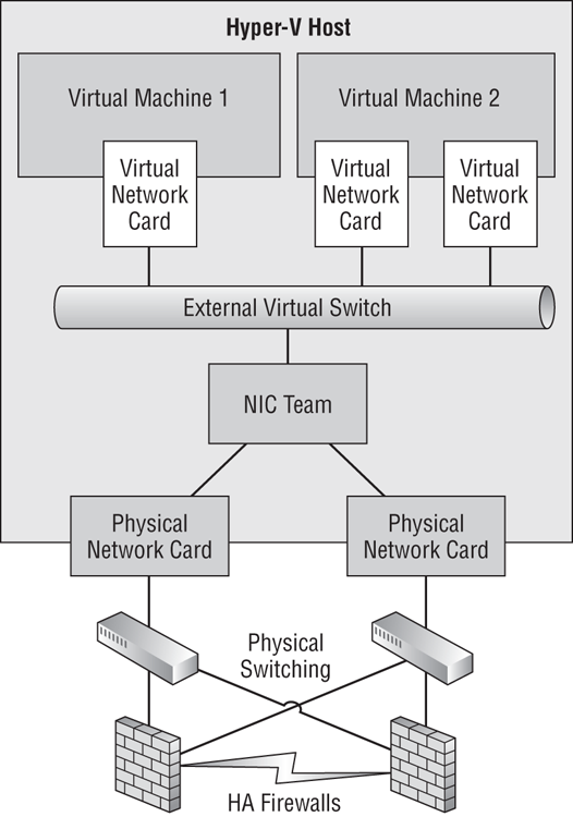
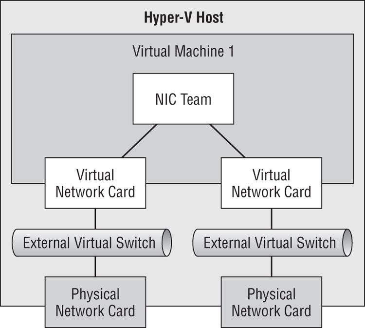
Are you wondering who in their right mind would want to create a NIC team in a virtual machine? In some scenarios, it is required—for example, when virtual NICs use Single-Root IO Virtualization (SR-IOV). When SR-IOV is enabled on a host, all connections to the physical NIC bypass much of the management OS, including NIC teaming. That means a virtual switch (and therefore all the connecting virtual machines) that is enabled for SR-IOV does not have network-path fault tolerance. We can solve that by providing two SR-IOV NICs in the host, each with its own virtual switch, and by putting two virtual NICs in each required virtual machine, and then by enabling NIC teaming in the virtual machine. You can see this scenario in Figure 4-13.
Figure 4-13 Enabling NIC teaming in a virtual machine for SR-IOV
Windows Server 2012 NIC teaming is not available for legacy operating systems, so you will need to use Windows Server 2012 as the guest OS for this architecture.
The process for creating the team inside the virtual machine will be the same as it is for a physical server. However, you must configure each virtual NIC that will be a team member in the virtual machine to allow NIC teaming. There are two ways to do this, both of which are available to only the Hyper-V administrator or cloud management system.
In Hyper-V Manager, you can do the following:
Alternatively, you can use PowerShell. The first example configures all virtual NICs to allow NIC teaming:
Set-VMNetworkAdapter -VMName “Virtual Machine 1” –AllowTeaming OnIf a virtual machine has many virtual NICs and you want to target this setting change, you could run this code snippet that uses an array to capture and configure the virtual NICs:
$VNICS = Get-VMNetworkAdapter -VMName “Virtual Machine 1”
Set-VMNetworkAdapter -VMNetworkAdapter $VNICS[0] -AllowTeaming On
Set-VMNetworkAdapter -VMNetworkAdapter $VNICS[1] -AllowTeaming On
Now these NICs are configured to support NIC teaming in the guest OS.
How will you configure switch dependency and load distribution in a guest OS NIC team? There is no choice to make; you will find that you can use only Switch-Independent teaming with Address Hashing inside a guest OS. A guest OS NIC team can be created with lots of virtual NICs, but Microsoft will support only the solution with two team members (virtual NICs in the team).
Creating and Configuring NIC Teams
After you have determined your NIC team design, you can create one. You can do this by using the GUI or PowerShell. In the GUI, you can get to the NIC Teaming utility in one of two ways, opening the window shown in Figure 4-14:
- Launch LBFOADMIN.EXE.
- Open Server Manager, browse to Local Server, and click the hyperlink beside NIC Teaming (which will be set to either Disabled or Enabled, depending on whether there is a NIC team).
Figure 4-14 The NIC Teaming console
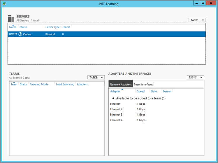
The Network Adapters view under Adapters And Interfaces shows the NICs that are installed in the machine as well as their speed and current team membership status. You can create a new team in two ways. The first is to select each NIC, expand Tasks under Adapters And Interfaces, and select Add To New Team. This opens the New Team window (Figure 4-15) with the NICs already preselected. The second method is to click Tasks under Teams and select New Team. This opens the New Team window with no NICs preselected. Now you will configure the team:
Figure 4-15 Creating a new NIC team
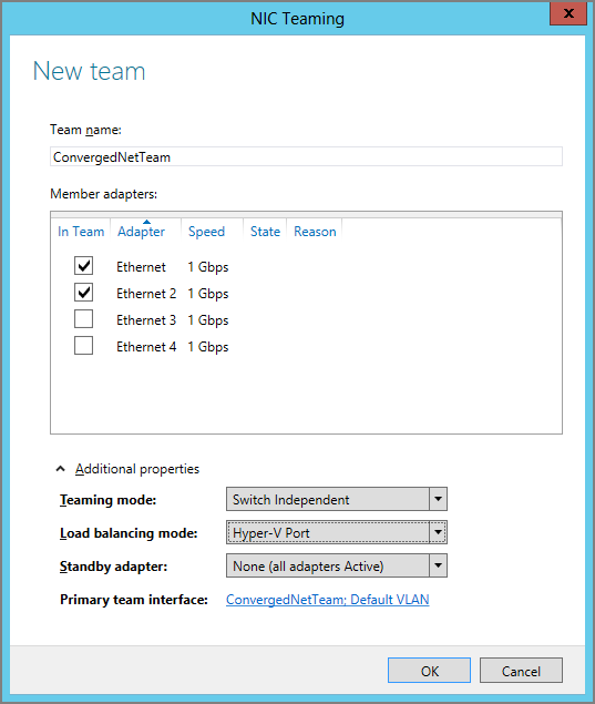
- Teaming Mode: Choose from Static Teaming (Switch-Dependent), Switch-Independent, and LACP (Switch-Dependent).
- Load Balancing Mode: The options are Address Hash and Hyper-V Port.
- Standby Adapter: This is available only in Switch-Independent teaming mode. You select which team member will be the hot standby if another member fails.
Your new team will be created when you click OK. The team will appear under Teams. The NICs will be shown as team members in Network Adapters under Adapters And Interfaces. The new NIC team will also appear as a Microsoft Network Adapter Multiplexor Driver in Network Connections using the NIC team name as the connection name.
You can also create a team by using PowerShell. The following example creates it in LACP Switch-Dependent mode, with Hyper-V Port load distribution, using two selected NICs. If every NIC was to be in the team, you could replace the names of the NICs with the * wildcard.
New-NetLBFOTeam -Name “ConvergedNetTeam” -TeamMembers “Ethernet”, “Ethernet `
2” -TeamingMode LACP -LoadBalancingAlgorithm HyperVPort -Confirm:$false
The -Confirm:$false flag and value instruct this cmdlet not to ask for confirmation. You can use this option with a cmdlet if there is no -Force flag. The -LoadBalancingAlgorithm flag requires some special attention. If not selected, it defaults to Address Hash. But if you want to specify a load-balancing algorithm, the cmdlet demands that you know precisely which kind of load distribution you require for your NIC team. It’s not just a matter of Hyper-V Port vs. Address Hashing, as in the GUI. The cmdlet breaks down the Address Hashing options into its four possible hashing methods:
- HyperVPort: The Hyper-V Port load distribution method.
- IPAddresses: 2-tuple hash but requires IP.
- MacAddresses: The least efficient but does not depend on IP.
- TransportPorts: 4-tuple hash is the most efficient but requires visibility of destination TCP/UDP ports.
If you want to keep it simple and duplicate what is in the GUI, do one of the following:
- Do not use the flag if you want generic Address Hashing.
- Use the flag and specify HyperVPort.
If this is a NIC team for normal server communications (in other words, not for a Hyper-V virtual switch), you can configure the protocols and IP addressing of the team interface in Network Connections. Do not configure the protocol settings of the team members. The only selected protocol in the team members should be Microsoft Network Adapter Multiplexor Protocol.
You can always return to the NIC Teaming console to modify or delete teams, and you can do the same in PowerShell by using Set-NetLBFOTeam and Remove-NetLBFOTeam. The full list of LBFO PowerShell cmdlets and their documentation can be found at http://technet.microsoft.com/library/jj130849.aspx.
The status of the team members is shown in Adapters And Interfaces, and the health of the team is in Teams. You can also retrieve team status information by using Get-NetLBFOTeam.
If a team or team members are immediately unhealthy after the creation of the team, double-check both the NIC team and the switch configurations. For example, an LACP team will be immediately unhealthy if the switches are incompatible; the NIC team will have a fault and the team members will change their state to Faulted: LACP Negotiation. You can also find status information for NIC teaming in Event Viewer at Application And Services Logs ⇒ Microsoft ⇒ Windows ⇒ MsLbfoProvider ⇒ Operational. Strangely, important issues such as a NIC being disabled create Information-level entries instead of Warning or Critical ones.
After your team is ready, you should test it for the LBFO functionality:
- Put outbound and inbound loads through the NIC team to determine the maximum throughput.
- Test the failover by removing a cable and/or disabling a NIC one at a time.
Creating and Configuring Team Interfaces
If your NIC team is not going to be used to connect a Hyper-V virtual switch to the physical network, you can add more team interfaces to the team. Each additional team interface will be in VLAN mode, binding it to a specific VLAN. This will allow the server in question to connect to multiple VLANs or subnets without the expense or complexity of adding more physical connections.
You can use the NIC Teaming console to add a team interface:
A new team interface is created when you click OK, and the team interface name will appear in Network Connections. You can then configure the protocols of this new connection.
The PowerShell alternative for creating a team interface (or team NIC) is as follows:
Add-NetLBFOTeamNIC -Team “ConvergedNetTeam” -Name “ConvergedNetTeam - VLAN `
102” -VLANID 102 -Confirm:$false
If the original team interface is not going to be used to connect a Hyper-V virtual switch, you can switch it from Default mode to VLAN mode by editing it in the GUI, or by running PowerShell:
Set-NetLBFOTeamNIC -Team ConvergedNetTeam -Name “ConvergedNetTeam” -VLANID 101You should be aware that changing the team interface to use a different VLAN will change its name from ConvergedNetTeam to ConvergedNetTeam - VLAN 101.
If you view the team interfaces in the NIC Teaming console or run Get-NetLBFOTeamNIC, you will see that one of the team interfaces is the primary team interface. This is the original team interface.
Connecting a Hyper-V Switch to the NIC Team
You can create a new virtual switch or change a virtual switch to use the NIC team. You can do this in Virtual Switch Manager by using these steps:
It’s a little easier in PowerShell because you can use the team interface name instead of the device name (InterfaceDescription). Here is how to modify an existing external virtual switch to use the team interface of a new NIC team:
Set-VMSwitch -Name External1 -NetAdapterName ConvergedNetTeamNow you know how to create, and importantly, design NIC teams to suit your workloads. Don’t go rushing off yet to create lots of NIC teams. First you’re going to want to learn how to take advantage of some powerful hardware features in Windows Server 2012 Hyper-V, and then you’ll get to read how you might need only one or two NIC teams in places where you might have used four or more in the past.