
OFDM and Multicarrier Signal Processing
Paolo Banelli and Luca Rugini, Dipartimento di Ingegneria, Università degli Studi di Perugia, Perugia, Italy, [email protected], [email protected]
Abstract
Orthogonal Frequency-Division Multiplexing (OFDM) is probably the topic that in the last two decades has motivated and attracted most of the research efforts and standardization activities for the physical layer of digital communication systems. Aim of this paper is to introduce the subject as a natural evolution from classical single-carrier (SC) systems, by preserving intuition and links to the underlying physical phenomena. The first part of the paper is a thorough introduction to OFDM and multicarrier (MC) communications, with a special emphasis on the mathematical models used to describe, design signal processing algorithms for, and analyze the performance of these communication systems. The second part of the paper is dedicated to highlight characteristics, merits, and drawbacks of OFDM and MC, with possible solutions to basic signal processing challenges, such as channel estimation and equalization, linear precoding, transmission in nonlinear channels, time-frequency synchronization, and bit/power loading algorithms.
Keywords
OFDM; Multicarrier; Orthogonality; DFT; frequency-selective multipath channels; Cyclic prefix
2.05.1 Introduction
Orthogonal Frequency-Division Multiplexing (OFDM) is indubitably a milestone in wired and wireless communications, which pervades most of the telecommunication standards developed in the last two decades, such as DAB, DVB-T/H, WiFi (IEEE 802.11a/n), WiMAX (IEEE 802.16e), UMTS-LTE, ADSL, etc. [71–73,104,105,107,237]. However, the OFDM principle dates back to the early 1960s for military communication systems [69,268]. More generally, the roots of OFDM are at the end of the nineteenth century when frequency division multiplexing (FDM) was investigated to increase the efficiency of telegraph systems [209], and successively was widely employed during the twentieth century in analog telephone lines [209]. Thus, OFDM is the typical example of a technology, whose idea has evolved theoretically for a long time, and that had to wait for mature electronic and software technologies to be implemented, at reasonable costs, for mass-market applications. The interested readers can find in [256] an excellent historical perspective of OFDM evolution, and a recent survey of OFDM literature in [103]. Additional information about OFDM and multicarrier techniques can be found in tutorial articles and books such as [12,29,53,120,136,145,251,269].
The success of OFDM with respect to classical single-carrier (SC) communications is mainly due to its capability to enable wideband communications in time-dispersive (frequency-selective) channels with low-complexity channel equalization, and high spectral efficiency. The simpler equalization with respect to SC is somehow borrowed from classical FDM, where the whole data stream is split in multiple sub-streams with lower data-rate (bandwidth), each one modulated by a different carrier frequency. This way, each sub-stream experiences an almost frequency-flat channel, which requests a simple equalization.
Additionally, OFDM doubles the spectral efficiency with respect to FDM by employing properly separated (e.g., orthogonal) carriers, which let the spectrum of each sub-stream overlap with one another [48]. By exploiting orthogonality, the multiple sub-streams can be separated at the receiver side by a bank of correlation-based receivers, rather than by the bandpass filtering of FDM, where the spectra of different sub-streams cannot overlap. Although the orthogonality principle is quite intuitive and mathematically simple, its implementation in the analog OFDM systems of the 1960s was requesting a bank of perfectly tuned oscillators, both at the transmitter and the receiver side, making OFDM implementation costly and limited to a small number of parallel carriers [268]. Actually, at the beginning of the 1970s, Weinstein and Ebert recognized that OFDM signals can be generated and demodulated by Fourier-based synthesis [257], foreseeing the substitution of the bank of analog oscillators by digital Discrete Fourier Transform (DFT) processing together with digital-to-analog (D/A) [and analog-to-digital (A/D)] conversion. The introduction of a cyclic-prefix (CP) between each transmitted symbol has been another crucial step towards easy OFDM implementation in frequency-selective channels, as firstly proposed in [179]. Thanks to the CP, the almost frequency-flat channel experienced by each sub-stream in the continuous domain, is turned in a perfectly flat channel in the discrete (e.g., DFT) domain. Thus, by standard DFT processing, OFDM is capable to convert the transmission of multiple symbols through a frequency-selective channel, in a set of independent parallel transmissions through a set of frequency-flat channels, which can be easily and independently equalized. When at the end of the 1980s, the progress of electronic technology (A/D and D/A converters, CPU clock frequencies, memories, etc.) made real-time digital signal processor (DSP) a reality, the concurrent increasing request for high data-rate transmissions in frequency-selective channels suggested that the time for OFDM “has come” [29]. At the beginning of the 1990s European broadcasting manufacturers and operators were among the first to recognize the potentiality of OFDM, by producing DAB and DVB-T as the first wireless communication standards for digital audio and video broadcasting [71,72,184].
Similarly, in the same decades, telephone companies and operators recognized to OFDM [or discrete multi-tone (DMT)], the capability to convey high data-rate bit-streams by classical twisted-pairs wires, practically solving the so called last-mile problem for widespread connection of user homes with high-speed digital communications. Indeed, according to the water-filling principle, the use of wires for digital communications permitted also to exploit the almost optimality of OFDM from the capacity point of view, as predicted by the famous Shannon’s paper in 1948 [212]. The first pioneering work of Cioffi and his co-workers on the subject [58], found successively full application in the ADSL standard [107].
The smart use of multiple antennas is another important milestone of wireless communications in the last two decades, while historically multiple antennas were only employed as a source of diversity at the receiver side. Conversely, it has been recognized that multiple transmit and receive antennas can boost the capacity of wireless links by multiple-input multiple-output (MIMO) systems [79], and improve coverage and connection quality by space-time (ST) coding [229]. For instance, the Alamouti ST-coding [5], currently adopted in several communications standards [such as [105]], is a remarkable example of a quite simple idea, which greatly improves the performance of a wireless communication link by employing only two transmit antennas and one, or more, receive antennas.
Anyway, both MIMO and ST-coding approaches have been conceived, and are quite easy to deploy, for SC communications on frequency-flat channels. Thus, the capability to convert frequency-selective channels in a set of parallel frequency-flat channels made OFDM the perfect tool to enable both MIMO and ST-coding techniques. However, this topic is out of the scope of this paper, which for space constraint will address only the fundamental signal processing aspects of OFDM and multicarrier (MC) communications. The interested readers are redirected to [84,88,178], and references therein, for an overview of MIMO and ST-coding, and to [37,111,263], for their use in OFDM-based systems. For a thorough introduction and deep survey of MIMO techniques, the interested readers are redirected to the E-Reference contribution of Davidson [66].
2.05.2 Mathematical background
The paper is written targeting an electrical engineering student with adequate background on Fourier transforms (continuous and discrete), signal and systems theory, linear algebra basics (vector, matrices, eigenvalues, eigenvector, singular value decomposition, etc.), basics of probability and estimation theory, and basics of digital communications. In order to better motivate why OFDM emerged and obscured classical SC communications in the last decades, the background on classical SC digital communications is summarized in the next paragraph, which is also useful to clarify similarities and differences between SC and OFDM systems.
2.05.3 Single carrier background
The baseband equivalent ![]() of a radio-frequency (RF) modulated signal
of a radio-frequency (RF) modulated signal
![]() (5.1)
(5.1)
which conveys a stream of digital information symbols ![]() by the RF carrier
by the RF carrier ![]() , has the general expression [183]
, has the general expression [183]
 (5.2)
(5.2)
Equation (5.2) highlights that in general the waveform ![]() associated to the
associated to the ![]() th symbol
th symbol ![]() may depend on a state variable
may depend on a state variable ![]() that takes into account some memory, i.e., dependence, on the previously emitted symbols, as it happens for instance for continuous-phase modulations [183]. Focusing on the simpler scenario of linear modulations without memory, (5.2) may be rewritten as
that takes into account some memory, i.e., dependence, on the previously emitted symbols, as it happens for instance for continuous-phase modulations [183]. Focusing on the simpler scenario of linear modulations without memory, (5.2) may be rewritten as
 (5.3)
(5.3)
where ![]() is the symbol period,
is the symbol period, ![]() is the symbol rate, and
is the symbol rate, and ![]() is the pulse-shaping filter that imposes the spectral occupancy.1 Specifically, for a given information stream, the spectrum of the transmitted signal is expressed by
is the pulse-shaping filter that imposes the spectral occupancy.1 Specifically, for a given information stream, the spectrum of the transmitted signal is expressed by
 (5.4)
(5.4)
where ![]() is the Fourier transform (FT) of
is the Fourier transform (FT) of ![]() , and
, and ![]() is the discrete-time FT (DTFT) of the transmitted sequence
is the discrete-time FT (DTFT) of the transmitted sequence ![]() . Thus, the information associated to each symbol
. Thus, the information associated to each symbol ![]() spreads by
spreads by ![]() throughout all the frequencies, it is mixed with the information associated to the other symbols
throughout all the frequencies, it is mixed with the information associated to the other symbols ![]() , and it is shaped (and band-limited) by
, and it is shaped (and band-limited) by ![]() .
.
The signal ![]() received on an additive white Gaussian noise (AWGN) channel is expressed by
received on an additive white Gaussian noise (AWGN) channel is expressed by
![]() (5.5)
(5.5)
where ![]() and
and ![]() represent attenuation and delay, respectively, and
represent attenuation and delay, respectively, and ![]() stands for the thermal receiver noise. Thus, the AWGN channel is characterized by the propagation of the transmitted signal through a linear system with impulse response
stands for the thermal receiver noise. Thus, the AWGN channel is characterized by the propagation of the transmitted signal through a linear system with impulse response ![]() , where
, where ![]() is the Dirac delta function. In order to recover the transmitted signal, and assuming
is the Dirac delta function. In order to recover the transmitted signal, and assuming ![]() and
and ![]() without restriction of generality, the receiver processes
without restriction of generality, the receiver processes ![]() by a filter
by a filter ![]() , which is responsible to maximize the signal-to-noise power-ratio (SNR), and to avoid inter-symbol interference (ISI) [183]. The SNR is maximized by a matched filter (MF), e.g.,
, which is responsible to maximize the signal-to-noise power-ratio (SNR), and to avoid inter-symbol interference (ISI) [183]. The SNR is maximized by a matched filter (MF), e.g., ![]() [183], leading to a filtered signal
[183], leading to a filtered signal ![]() expressed by
expressed by
 (5.6)
(5.6)
In (5.6), ![]() stands for the linear convolution operator,
stands for the linear convolution operator, ![]() is the complex-conjugate operator,
is the complex-conjugate operator, ![]() is the pulse-shape autocorrelation function, and
is the pulse-shape autocorrelation function, and ![]() is the filtered noise. Thus, the MF is also known as correlator receiver [183]. If the pulse shaper
is the filtered noise. Thus, the MF is also known as correlator receiver [183]. If the pulse shaper ![]() is designed with unit energy
is designed with unit energy ![]() and such that
and such that ![]() , the sample
, the sample ![]() extracted at
extracted at ![]() is expressed by
is expressed by
 (5.7)
(5.7)
do not experience any ISI from adjacent symbols, and optimal reception can be performed on a symbol by symbol basis [183]. The ISI-free constraint on ![]() imposes a constraint on its FT
imposes a constraint on its FT ![]() , which has to be shaped such that [183]
, which has to be shaped such that [183]
 (5.8)
(5.8)
The ISI-free constraint in (5.8) can be satisfied if ![]() has an anti-symmetrical shape with respect to the frequency
has an anti-symmetrical shape with respect to the frequency ![]() and
and ![]() when
when ![]() (see Figure 5.1). This is known as the Nyquist criterion, and suggests that the positive (half) bandwidth
(see Figure 5.1). This is known as the Nyquist criterion, and suggests that the positive (half) bandwidth ![]() associated with a linear digital modulation is
associated with a linear digital modulation is ![]() , where
, where ![]() . A typical prototype filter that respects such constraints is the root raised-cosine filter [183], whose shape is shown in Figure 5.1 together with the graphical interpretation of (5.8).
. A typical prototype filter that respects such constraints is the root raised-cosine filter [183], whose shape is shown in Figure 5.1 together with the graphical interpretation of (5.8).

However, in most of wireless and wired communication systems, the propagation channel is not AWGN. Indeed, because of multipath propagation in wireless communications [222], and of frequency-dependent attenuation in wired communications [183], the propagation channel is modeled by a frequency-selective channel with a time-dispersive impulse response ![]() .
.
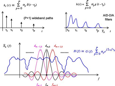
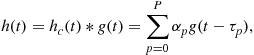
A typical baseband representation for a linear time-invariant (LTI) channel, with ![]() path is summarized by its time-dispersive impulse response
path is summarized by its time-dispersive impulse response
 (5.9)
(5.9)
where ![]() and
and ![]() are the attenuation and delay, respectively, associated with the
are the attenuation and delay, respectively, associated with the ![]() th path, and
th path, and
 (5.10)
is the frequency-selective channel spectrum, as shown in Figure 5.6.
In the presence of a time-dispersive (frequency-selective) channel, the received signal at the MF output is expressed by
 (5.11)
where ![]() is the overall pulse shape that is perceived at the receiver side. The effect of the channel in the frequency-domain is captured by
is the overall pulse shape that is perceived at the receiver side. The effect of the channel in the frequency-domain is captured by
![]() (5.12)
(5.12)
where ![]() replaces the role of
replaces the role of ![]() in (5.8).
in (5.8).
Thus, if ![]() is not constant in the frequency support where
is not constant in the frequency support where ![]() , e.g., if
, e.g., if ![]() when
when ![]() , the frequency selectivity of the physical channel destroys the ISI-free design of Figure 5.1. This means that, in the presence of multipath (frequency-selectivity), the time dispersion of the channel
, the frequency selectivity of the physical channel destroys the ISI-free design of Figure 5.1. This means that, in the presence of multipath (frequency-selectivity), the time dispersion of the channel ![]() destroys the ISI-free design, because
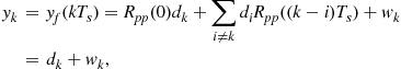
destroys the ISI-free design, because ![]() , and the received samples at the MF output become
, and the received samples at the MF output become
![]() (5.13)
(5.13)
where ![]() is the equivalent discrete-time impulse response of the overall channel, which is generally modeled as a finite impulse response (FIR) filter of order
is the equivalent discrete-time impulse response of the overall channel, which is generally modeled as a finite impulse response (FIR) filter of order ![]() .
.
The presence of ISI from adjacent symbols requests both the estimation of the channel coefficients ![]() and more complex detection techniques. For equiprobable transmitted symbols, the optimal detection choice consists in a maximum likelihood (ML) receiver that can exploit the Viterbi algorithm [183], whose complexity grows exponentially with the discrete-time channel length
and more complex detection techniques. For equiprobable transmitted symbols, the optimal detection choice consists in a maximum likelihood (ML) receiver that can exploit the Viterbi algorithm [183], whose complexity grows exponentially with the discrete-time channel length ![]() . Alternative and simpler detection schemes, characterized by (sometimes significant) bit-error-rate (BER) performance degradation, first try to counteract the effect of the channel by a linear filter (equalizer), and successively resort to a single-symbol decision as in (5.7). The simplest choice for the linear equalizer is represented by a transversal FIR filter, whose coefficients (taps) can be determined according to different criteria [zero-forcing, minimum mean-squared error (MMSE), etc. [183]]. The channel equalization complexity for each transmitted symbol
. Alternative and simpler detection schemes, characterized by (sometimes significant) bit-error-rate (BER) performance degradation, first try to counteract the effect of the channel by a linear filter (equalizer), and successively resort to a single-symbol decision as in (5.7). The simplest choice for the linear equalizer is represented by a transversal FIR filter, whose coefficients (taps) can be determined according to different criteria [zero-forcing, minimum mean-squared error (MMSE), etc. [183]]. The channel equalization complexity for each transmitted symbol ![]() , without considering the channel estimation and the equalizer design, is linearly proportional to the number of taps
, without considering the channel estimation and the equalizer design, is linearly proportional to the number of taps ![]() of the FIR equalizer. Typically the FIR equalizer suffers from noise amplification and gives acceptable BER performance, when
of the FIR equalizer. Typically the FIR equalizer suffers from noise amplification and gives acceptable BER performance, when ![]() . Thus, we can conclude that the simplest linear equalization in SC is characterized by a complexity for transmitted symbol that grows linearly with the channel order
. Thus, we can conclude that the simplest linear equalization in SC is characterized by a complexity for transmitted symbol that grows linearly with the channel order ![]() , rather than exponentially as for ML equalizers.
, rather than exponentially as for ML equalizers.
Another possibility to contrast the effect of the ISI, and avoid the noise amplification associated with linear equalization is to use decision feedback equalization, which is a nonlinear data-aided approach that represents a trade-off between BER performance and computational complexity [183].
It is important to observe that any physical channel is characterized by its own frequency selectivity and coherence bandwidth ![]() , i.e., a band
, i.e., a band ![]() where
where ![]() is almost constant. If the frequency support of the transmitted signal is within the channel coherence bandwidth, i.e., if the bandwidth of
is almost constant. If the frequency support of the transmitted signal is within the channel coherence bandwidth, i.e., if the bandwidth of ![]() is
is ![]() , the channel will not significantly alter the ISI-free design of Eq. (5.8) and Figure 5.1, which will be almost respected by
, the channel will not significantly alter the ISI-free design of Eq. (5.8) and Figure 5.1, which will be almost respected by ![]() . On the contrary, the effect of ISI becomes critical if the system symbol rate
. On the contrary, the effect of ISI becomes critical if the system symbol rate ![]() increases, leading to a proportional increase of the system bandwidth
increases, leading to a proportional increase of the system bandwidth ![]() (see Figure 5.1), which may become greater than the coherence bandwidth
(see Figure 5.1), which may become greater than the coherence bandwidth ![]() . In the discrete-time domain, the increase of the symbol rate would correspond to an increased number
. In the discrete-time domain, the increase of the symbol rate would correspond to an increased number ![]() of channel coefficients
of channel coefficients ![]() [222], and consequently an increased complexity for the channel equalizer.
[222], and consequently an increased complexity for the channel equalizer.
Just to give an idea, a wireless SC system in a urban environment is typically characterized by a multipath channel ![]() with a maximum delay spread
with a maximum delay spread ![]() [60]: if the requested system capacity can be granted by a bandwidth
[60]: if the requested system capacity can be granted by a bandwidth ![]() , this means that the channel length is of the order
, this means that the channel length is of the order ![]() , and a linear transversal FIR equalizers with at least
, and a linear transversal FIR equalizers with at least ![]() taps is request to obtain acceptable BER performance. Needless to say that in this scenario it is impossible to think about ML equalization/detection, whose complexity is exponential in
taps is request to obtain acceptable BER performance. Needless to say that in this scenario it is impossible to think about ML equalization/detection, whose complexity is exponential in ![]() .
.
Thus, the ever increasing demand for high data-rate communications in the last decades has posed tremendous challenges to channel estimation and equalization of classical SC wideband communications. This was the main motivation, even if not the single one, to look for an alternative communication scheme that could more easily handle the propagation through frequency-selective (multipath) channels.
2.05.4 The path to OFDM
This section is dedicated to show how the OFDM principle can naturally evolve from SC communications, through the classical concept of FDM.
2.05.4.1 Frequency division multiplexing
When the information stream ![]() is characterized by a very-high symbol rate
is characterized by a very-high symbol rate ![]() , a natural way to deal with the frequency selectivity of the channel is to split the data stream into M multiple parallel sub-streams. This way, each sub-stream is characterized by a reduced symbol rate
, a natural way to deal with the frequency selectivity of the channel is to split the data stream into M multiple parallel sub-streams. This way, each sub-stream is characterized by a reduced symbol rate ![]() and, consequently, can be transmitted by a baseband signal
and, consequently, can be transmitted by a baseband signal ![]() expressed by
expressed by
 (5.14)
where ![]() represents a serial-to-parallel (S/P) conversion, and
represents a serial-to-parallel (S/P) conversion, and ![]() is the pulse-shaping waveform of the
is the pulse-shaping waveform of the ![]() th sub-stream. The simplest way to separate
th sub-stream. The simplest way to separate ![]() data streams at RF was historically offered by FDM [29], where all the streams are characterized by the same bandwidth
data streams at RF was historically offered by FDM [29], where all the streams are characterized by the same bandwidth ![]() , and are modulated at RF on different (sub-) carriers
, and are modulated at RF on different (sub-) carriers ![]() . The subcarrier separation
. The subcarrier separation ![]() grants that each sub-stream can be separated from the others by simple band-pass filtering at the receiver side (see
grants that each sub-stream can be separated from the others by simple band-pass filtering at the receiver side (see ![]() in Figure 5.2), followed by a classical MF receiver for each sub-stream.
in Figure 5.2), followed by a classical MF receiver for each sub-stream.
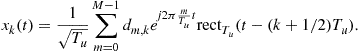
Thus, taking into account (5.1), the equivalent baseband model of the overall transmitted stream is simply represented by the superposition of the ![]() parallel baseband streams, as expressed by
parallel baseband streams, as expressed by
 (5.15)
where
![]() (5.16)
(5.16)
and ![]() , thus producing a multicarrier (MC) communication system.
, thus producing a multicarrier (MC) communication system.
As for SC communications, the role of ![]() is twofold, i.e., to shape the spectrum
is twofold, i.e., to shape the spectrum ![]() and to guarantee ISI-free reception by the receiver MF of each single sub-stream. The role of
and to guarantee ISI-free reception by the receiver MF of each single sub-stream. The role of ![]() is to shift in frequency each single sub-stream, such that the sub-streams are almost separated, i.e.,
is to shift in frequency each single sub-stream, such that the sub-streams are almost separated, i.e., ![]() : this way, each single sub-stream can be easily separated by bandpass filtering (see also Figure 5.2). In practice, in order to filter each sub-stream with physically realizable filters, it is also necessary to introduce a frequency guard-band
: this way, each single sub-stream can be easily separated by bandpass filtering (see also Figure 5.2). In practice, in order to filter each sub-stream with physically realizable filters, it is also necessary to introduce a frequency guard-band ![]() between adjacent frequency channels and, consequently,
between adjacent frequency channels and, consequently, ![]() . Thus, the overall RF spectral occupancy is
. Thus, the overall RF spectral occupancy is ![]() and FDM sacrifices spectral efficiency with respect to the SC solution, whose spectrum support is
and FDM sacrifices spectral efficiency with respect to the SC solution, whose spectrum support is ![]() (see Figure 5.1)5.2 .
(see Figure 5.1)5.2 .

2.05.4.2 Orthogonal multiplexing principle
The multiple-stream expression in (5.14) and (5.15) may have a much broader interpretation than simple FDM. On one hand, in order to allow for a simple receiver architecture, e.g., a parallel of ![]() SC-like receivers (see Figure 5.3), the pulse shaper
SC-like receivers (see Figure 5.3), the pulse shaper ![]() has to guarantee the maximum SNR by MF and the ISI-free properties of each single sub-stream, as in FDM. On the other hand, additionally, the pulse shaper
has to guarantee the maximum SNR by MF and the ISI-free properties of each single sub-stream, as in FDM. On the other hand, additionally, the pulse shaper ![]() should guarantee the absence of interference from the other (superimposed)
should guarantee the absence of interference from the other (superimposed) ![]() sub-streams.
sub-streams.
By means of (5.6), the output of the ![]() th MF is
th MF is
 (5.17)
which, assuming the ISI-free design for ![]() and a sampling rate
and a sampling rate ![]() , corresponds to a discrete-time signal expressed by
, corresponds to a discrete-time signal expressed by
 (5.18)
Equation (5.18) highlights that the interference caused by the symbols ![]() of the other streams
of the other streams ![]() can be eliminated if, and only if, the pulse-shaper cross-correlation
can be eliminated if, and only if, the pulse-shaper cross-correlation ![]() is characterized by equispaced samples
is characterized by equispaced samples ![]() .
.
For practical considerations, such as the transmission of a symbol in a limited time, it is natural to consider pulse shapers with a limited duration (time support) ![]() . To this end, let us express the
. To this end, let us express the ![]() th pulse shaper as
th pulse shaper as
![]() (5.19)
(5.19)
where ![]() when
when ![]() and
and ![]() elsewhere, and
elsewhere, and ![]() contains the shape of the pulse within the limited time support. The finite time support
contains the shape of the pulse within the limited time support. The finite time support ![]() leads also to autocorrelation and cross-correlation functions with limited time-support
leads also to autocorrelation and cross-correlation functions with limited time-support ![]() , i.e.,
, i.e., ![]() when
when ![]() , for
, for ![]() . Thus, choosing
. Thus, choosing ![]() would easily guarantee that
would easily guarantee that ![]() when
when ![]() . This allows for the elimination of the ISI caused by those symbols (of all the
. This allows for the elimination of the ISI caused by those symbols (of all the ![]() sub-streams) transmitted in the interval
sub-streams) transmitted in the interval ![]() , where
, where ![]() is the interval index of the target symbol. Thus, for time-limited pulse shapers with unit energy
is the interval index of the target symbol. Thus, for time-limited pulse shapers with unit energy ![]() and duration
and duration ![]() , (5.18) reduces to
, (5.18) reduces to
![]() (5.20)
(5.20)
where the ![]() th stream suffers only from the interference caused by those symbols (of the
th stream suffers only from the interference caused by those symbols (of the ![]() sub-streams with
sub-streams with ![]() ) transmitted during the same
) transmitted during the same ![]() th symbol interval. In order to avoid such an interference, it is necessary to design the
th symbol interval. In order to avoid such an interference, it is necessary to design the ![]() pulses such that
pulses such that
![]() (5.21)
(5.21)
which means that the pulse shapers have to be orthogonal over the finite support ![]() . Therefore, for
. Therefore, for ![]() orthogonal and unit-energy design of the pulse shapers, the output of the
orthogonal and unit-energy design of the pulse shapers, the output of the ![]() th MF branch in Figure 5.3, is expressed by
th MF branch in Figure 5.3, is expressed by
![]() (5.22)
(5.22)
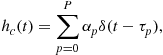
There are wide classes of functions that are orthogonal over a finite interval, and every choice would be equivalent in this respect. By such a design, the system in Figure 5.3 is nothing else than a classical (short) code-division multiple-access (CDMA) receiver [183], where ![]() is the signature waveform (i.e., the pulse-shaped code) associated with the
is the signature waveform (i.e., the pulse-shaped code) associated with the ![]() th sub-stream. The interested reader can refer to [247] for further details on CDMA principles and systems, and Section 2.05.10.2 for a comparison of MC and CDMA philosophies.
th sub-stream. The interested reader can refer to [247] for further details on CDMA principles and systems, and Section 2.05.10.2 for a comparison of MC and CDMA philosophies.
2.05.4.3 Orthogonal frequency-division multiplexing principle
Noteworthy, the exponential functions ![]() involved in the FDM design are candidate functions for
involved in the FDM design are candidate functions for ![]() in (5.21), if the frequencies
in (5.21), if the frequencies ![]() are carefully selected. Indeed, in order to approximate any regular function on a finite time-interval, the Fourier series [173] exploits orthogonal exponential functions whose frequencies are proportional to the fundamental frequency
are carefully selected. Indeed, in order to approximate any regular function on a finite time-interval, the Fourier series [173] exploits orthogonal exponential functions whose frequencies are proportional to the fundamental frequency ![]() , e.g.,
, e.g., ![]() . This way the baseband spectrum would exploit only positive frequencies, and in order to be consistent with (5.1) where
. This way the baseband spectrum would exploit only positive frequencies, and in order to be consistent with (5.1) where ![]() is the central RF spectrum frequency, it would be necessary to use
is the central RF spectrum frequency, it would be necessary to use ![]() . However, this choice implies only a fixed frequency shift of the spectrum, which is inessential. Thus, in the rest of the paper the frequency shift
. However, this choice implies only a fixed frequency shift of the spectrum, which is inessential. Thus, in the rest of the paper the frequency shift ![]() is ignored, which can also be interpreted as assuming
is ignored, which can also be interpreted as assuming ![]() as the RF central frequency.
as the RF central frequency.
Consequently, a multicarrier design that guarantees an easy sub-stream separation exploits
![]() (5.23)
(5.23)
and the overall transmitted signal is expressed by
 (5.24)
Equation (5.23) is analogous to (5.16) for FDM, where ![]() : this fact highlights that the system designed with (5.23) and (5.24) is a special FDM system that exploits (baseband) orthogonal frequencies
: this fact highlights that the system designed with (5.23) and (5.24) is a special FDM system that exploits (baseband) orthogonal frequencies ![]() and, as such, is typically called OFDM.
and, as such, is typically called OFDM.
However, the philosophy of OFDM is noticeably different from FDM, as can be noted from the following observations:
a. The ISI-free condition for each sub-stream is granted by a pulse shaper ![]() with a finite time-support
with a finite time-support ![]() .
.
b. The rectangular pulse shaper ![]() induces, for each sub-stream, a baseband spectrum with
induces, for each sub-stream, a baseband spectrum with ![]() . Thus, each sub-stream is not band-limited, although a high percentage of its energy is mainly concentrated into its main lobe, i.e., on an RF frequency support equal to
. Thus, each sub-stream is not band-limited, although a high percentage of its energy is mainly concentrated into its main lobe, i.e., on an RF frequency support equal to ![]() .
.
c. The spectra ![]() of different sub-streams, separated by
of different sub-streams, separated by ![]() , are not disjoint in the frequency-domain and they significantly overlap with the adjacent ones (see Figure 5.4).
, are not disjoint in the frequency-domain and they significantly overlap with the adjacent ones (see Figure 5.4).

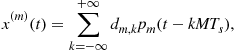
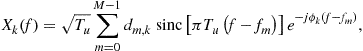
We now focus on the signal ![]() associated with a block of
associated with a block of ![]() parallel symbols transmitted during a single OFDM interval of duration
parallel symbols transmitted during a single OFDM interval of duration ![]() , expressed by
, expressed by
 (5.25)
The signal ![]() in (5.25), or equivalently the data
in (5.25), or equivalently the data ![]() in (5.25), is usually denoted as the
in (5.25), is usually denoted as the ![]() th OFDM symbol or the
th OFDM symbol or the ![]() th OFDM block. The spectrum associated with the single OFDM block in (5.25) is
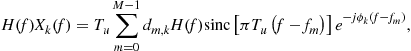
th OFDM block. The spectrum associated with the single OFDM block in (5.25) is
 (5.26)
where ![]() is a linear-phase term that takes into account the delay associated with the
is a linear-phase term that takes into account the delay associated with the ![]() th OFDM block. Observing the shape of
th OFDM block. Observing the shape of ![]() in Figure 5.4 (where the phase
in Figure 5.4 (where the phase ![]() is not considered for simplicity), it is evident that the transmission of an OFDM symbol corresponds to the parallel transmission of
is not considered for simplicity), it is evident that the transmission of an OFDM symbol corresponds to the parallel transmission of ![]() data symbols
data symbols ![]() , each one modulating the amplitude of a pulse-shaper spectrum
, each one modulating the amplitude of a pulse-shaper spectrum ![]() . From the same figure, it is also evident that the middle points of the
. From the same figure, it is also evident that the middle points of the ![]() overlapping spectra are equispaced in the frequency-domain, by
overlapping spectra are equispaced in the frequency-domain, by ![]() . Thus, also the data overlap (interfere) in the frequency-domain, except in the equispaced locations of the zeros of each sinc-like spectrum where
. Thus, also the data overlap (interfere) in the frequency-domain, except in the equispaced locations of the zeros of each sinc-like spectrum where
![]() (5.27)
(5.27)
Consequently, as Figure 5.4 clarifies, OFDM performs in the frequency-domain a dual operation of SC transmissions in the time-domain: the equispaced zero-location property of ![]() at frequencies
at frequencies ![]() is the dual of the equispaced zero-location property of
is the dual of the equispaced zero-location property of ![]() that grants ISI-free transmission at
that grants ISI-free transmission at ![]() in SC systems. In this case,
in SC systems. In this case, ![]() are the points in the frequency-domain where the symbols
are the points in the frequency-domain where the symbols ![]() belonging to different subcarriers do not interfere with each other. In the multicarrier literature [29,59,94,196,246], this kind of interference is called intercarrier interference (ICI), or interchannel interference: OFDM is characterized by an ICI-free design for
belonging to different subcarriers do not interfere with each other. In the multicarrier literature [29,59,94,196,246], this kind of interference is called intercarrier interference (ICI), or interchannel interference: OFDM is characterized by an ICI-free design for ![]() .
.
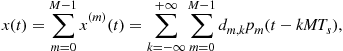
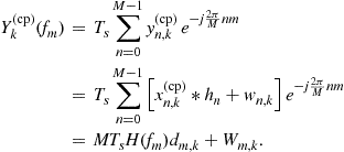
Figure 5.4 suggests that in order to recover the data ![]() transmitted during the
transmitted during the ![]() th OFDM block, it would be sufficient to sample its spectrum at the frequencies
th OFDM block, it would be sufficient to sample its spectrum at the frequencies ![]() . Indeed, the signal received in an AWGN channel during the
. Indeed, the signal received in an AWGN channel during the ![]() th OFDM block is
th OFDM block is
 (5.28)
and the output ![]() of the
of the ![]() th receiver branch in (5.22) is expressed by
th receiver branch in (5.22) is expressed by
 (5.29)
which confirms the intuition that in the OFDM case the optimal parallel MF architecture in Figure 5.3 actually performs an equispaced (frequency-domain) sampling of the received spectrum.
2.05.4.4 DFT-based implementation of OFDM
By the Nyquist-Shannon sampling theorem [213], it is well known that an equispaced spectrum sampling of a band-limited signal can be accomplished by the DFT of its time-domain samples, collected with a sampling frequency ![]() in order to avoid aliasing. Actually, the spectrum
in order to avoid aliasing. Actually, the spectrum ![]() in Figure 5.4 is not rigorously band-limited, because of the everlasting tails of the
in Figure 5.4 is not rigorously band-limited, because of the everlasting tails of the ![]() function associated to the rectangular pulse shaper
function associated to the rectangular pulse shaper ![]() in (5.19). However, if the sampling frequency is chosen such that
in (5.19). However, if the sampling frequency is chosen such that ![]() , where
, where ![]() is a positive integer, by the Nyquist sampling theorem the sampled signal
is a positive integer, by the Nyquist sampling theorem the sampled signal
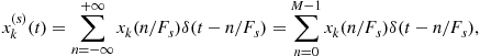 (5.30)
has a spectrum that is the sum of the replicas of the original spectrum, as summarized by
 (5.31)
Due to the fact that also the spectral aliases are centered at integer multiples of the OFDM symbol frequency ![]() , also (some of) the zeros of their sinc-like functions will coincide with the orthogonal frequencies
, also (some of) the zeros of their sinc-like functions will coincide with the orthogonal frequencies ![]() . Thus, aliasing is null on the frequency grid
. Thus, aliasing is null on the frequency grid ![]() where the spectrum is sampled in order to recover the transmitted data
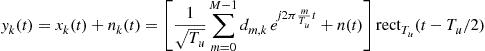
where the spectrum is sampled in order to recover the transmitted data ![]() . In formulas, when
. In formulas, when ![]() , i.e., when the signal is sampled at the receiver side by
, i.e., when the signal is sampled at the receiver side by ![]() , and ignoring the presence of the noise, we have
, and ignoring the presence of the noise, we have
 (5.32)
The last equation highlights that the receiver can recover the transmitted data ![]() by sampling the spectrum of the (discrete-time) received signal. In the absence of noise, sampling the spectrum of the discrete-time received signal corresponds to compute
by sampling the spectrum of the (discrete-time) received signal. In the absence of noise, sampling the spectrum of the discrete-time received signal corresponds to compute
 (5.33)
which, by the last equality [173], corresponds to compute the DFT of the discrete-time sequence ![]() , scaled by
, scaled by ![]() .
.
Consequently, also the inverse is true by exploiting the properties of DFT, i.e., the transmitted discrete-time symbols ![]() can be obtained by the inverse DFT (IDFT) of the spectrum samples
can be obtained by the inverse DFT (IDFT) of the spectrum samples ![]() , scaled by
, scaled by ![]() . This can be also easily verified by direct substitution in (5.25), which leads to
. This can be also easily verified by direct substitution in (5.25), which leads to
 (5.34)
Equations (5.33) and (5.34) highlight that an efficient digital implementation of OFDM is possible by exploiting (inverse) fast Fourier transform (FFT) algorithms for (inverse) DFT computations [173]. This observation was first recognized in [257] and it is at the base of the renewed interest in OFDM between 1980 and 1990, when the sampling frequencies of A/D and D/A converters, as well as the clock frequencies of integrated circuits (IC) and memories, have started to become compatible with a real-time implementation. It was indeed at the end of that decade that the first mass-market commercial OFDM standards were deployed, namely digital audio broadcasting (DAB) [71] and digital video broadcasting-terrestrial (DVB-T) [72].
2.05.5 OFDM in frequency-selective multipath channels
Note that, the architecture in Figure 5.5 has solved only the problem of efficiently separating ![]() parallel streams in AWGN channels. In the presence of frequency-selective (multipath) channels, each of the
parallel streams in AWGN channels. In the presence of frequency-selective (multipath) channels, each of the ![]() orthogonal single (sub-) carrier systems would suffer from the classical problem of ISI. However, the reduction of the symbol rate of each stream to
orthogonal single (sub-) carrier systems would suffer from the classical problem of ISI. However, the reduction of the symbol rate of each stream to ![]() leads to consequent reduction, by a factor
leads to consequent reduction, by a factor ![]() , of the length of the discrete-time impulse response
, of the length of the discrete-time impulse response ![]() associated with each of the
associated with each of the ![]() parallel systems. Thus, the OFDM system could be equalized by
parallel systems. Thus, the OFDM system could be equalized by ![]() parallel SC equalizers. As we already mentioned at the end of Section 2.05.1, the complexity grows linearly and exponentially with the channel length for time-domain linear and ML equalization, respectively [183]: thus we can immediately conclude that the equalization complexity of OFDM is significantly reduced with respect to a SC system with the same bandwidth. Furthermore, we will show that the smart use of time guards further reduces OFDM equalization, by a frequency-domain approach.
parallel SC equalizers. As we already mentioned at the end of Section 2.05.1, the complexity grows linearly and exponentially with the channel length for time-domain linear and ML equalization, respectively [183]: thus we can immediately conclude that the equalization complexity of OFDM is significantly reduced with respect to a SC system with the same bandwidth. Furthermore, we will show that the smart use of time guards further reduces OFDM equalization, by a frequency-domain approach.
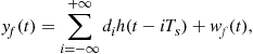
In order to identify how to recover the transmitted data also in the presence of a frequency-selective channel, let us investigate the expression for the received signal in case of a typical time-invariant multipath propagation, as shown in Figure 5.6 and summarized by
 (5.35)
where ![]() has been defined in (5.9), and
has been defined in (5.9), and ![]() captures the low-pass filtering included in the A/D and D/A converters, as well as the baseband (BB) equivalent of the band-pass filtering stages in the RF-to-BB and the BB-to-RF conversion.
captures the low-pass filtering included in the A/D and D/A converters, as well as the baseband (BB) equivalent of the band-pass filtering stages in the RF-to-BB and the BB-to-RF conversion.
To better understand the effect of the channel, and the potential resistance of OFDM to multipath propagation, first it is convenient to consider the spectrum of the received signal, which is given by
![]() (5.36)
(5.36)
Focusing on a single OFDM symbol, the useful part of the spectrum (i.e., ignoring the noise) is expressed by
 (5.37)
which clarifies that a frequency-selective channel ![]() does not destroy the orthogonality of the transmitted data on the equispaced frequency grid
does not destroy the orthogonality of the transmitted data on the equispaced frequency grid ![]() , as shown in Figure 5.1, and summarized by
, as shown in Figure 5.1, and summarized by
![]() (5.38)
(5.38)
Thus, the receiver can effectively separate and detect the data transmitted during a single OFDM block, still by sampling the OFDM spectrum of the received signal ![]() . However, in time-dispersive channels, because of the convolution with the channel impulse response (CIR) (5.35), the duration of each single received OFDM block will be longer than
. However, in time-dispersive channels, because of the convolution with the channel impulse response (CIR) (5.35), the duration of each single received OFDM block will be longer than ![]() . If the CIR
. If the CIR ![]() has a time support (duration)
has a time support (duration) ![]() , the received OFDM block
, the received OFDM block ![]() will have duration
will have duration ![]() , as shown in Figure 5.7.
, as shown in Figure 5.7.

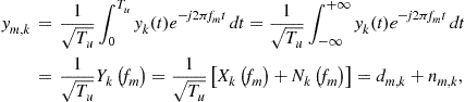
Thus, sampling the OFDM spectrum of the 0th block requests to compute
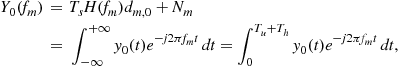 (5.39)
which can be obtained by the DTFT of the sequence ![]() , evaluated at
, evaluated at ![]() , as expressed by
, as expressed by
 (5.40)
Note that (5.40) is quite similar to a DFT processing: the only difference is that the summation index ![]() exceeds the DFT period
exceeds the DFT period ![]() . However, because of the periodicity of the discrete Fourier exponentials, i.e.,
. However, because of the periodicity of the discrete Fourier exponentials, i.e., ![]() , it is evident that
, it is evident that
 (5.41)
Equation (5.41) highlights that the sampling can still be performed by an ![]() -point DFT processing, on a new
-point DFT processing, on a new ![]() -length sequence
-length sequence ![]() obtained adding to the received sequence
obtained adding to the received sequence ![]() its replica anticipated by
its replica anticipated by ![]() discrete-time indexes, by an overlap-and-add strategy [173]. This way, the tail of
discrete-time indexes, by an overlap-and-add strategy [173]. This way, the tail of ![]() that exceeds the transmitted length
that exceeds the transmitted length ![]() is added at the beginning of the original sequence, as shown in Figure 5.8, making (5.41) equivalent to (5.40).
is added at the beginning of the original sequence, as shown in Figure 5.8, making (5.41) equivalent to (5.40).

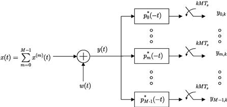
2.05.5.1 Zero-padded OFDM (ZP-OFDM)
Equation (5.38), and consequently (5.41), has shown a simple receiving strategy that preserves orthogonality among the subcarriers at the receiver side, also in the presence of a time-dispersive channel. This strategy, which has not been outlined in any of the historical and classical papers on OFDM [29,59,257], is an alternative to the CP-OFDM transmission that will be described shortly. However, note that (5.41) alone leads to a simple DFT-based receiver in frequency-selective channels, for a single OFDM block. Actually, the transmission of consecutive OFDM blocks through a time-dispersive channel would introduce ISI between successive blocks, typically called inter-block interference (IBI), as shown in Figure 5.9.
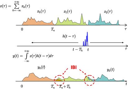
This means that (5.41) avoids the ISI between different subcarriers (i.e., the ICI), but each (sub-) SC signal ![]() that constitutes the overall OFDM signal still suffers from the ISI between adjacent symbol periods of duration
that constitutes the overall OFDM signal still suffers from the ISI between adjacent symbol periods of duration ![]() (i.e., IBI). Anyway, by designing
(i.e., IBI). Anyway, by designing ![]() , i.e., by employing a high number
, i.e., by employing a high number ![]() of carriers, the IBI impairs only a small fraction of the symbol period
of carriers, the IBI impairs only a small fraction of the symbol period ![]() . Consequently, the performance degradation induced on each (sub-) SC system would be much lower than for a single SC system with the same data rate, whose symbol duration is
. Consequently, the performance degradation induced on each (sub-) SC system would be much lower than for a single SC system with the same data rate, whose symbol duration is ![]() . Obviously, there exist methods to compensate for such IBI (i.e., equalization algorithms), as we will detail later on; however, if the goal is a very low-complexity receiver, it would be easy to deterministically avoid IBI by designing an OFDM system that inserts a silent period
. Obviously, there exist methods to compensate for such IBI (i.e., equalization algorithms), as we will detail later on; however, if the goal is a very low-complexity receiver, it would be easy to deterministically avoid IBI by designing an OFDM system that inserts a silent period ![]() (i.e., a time-guard) between consecutive OFDM symbols. This approach, shown in Figure 5.10, is summarized by
(i.e., a time-guard) between consecutive OFDM symbols. This approach, shown in Figure 5.10, is summarized by
 (5.42)
where ![]() , is the new duration of each OFDM block, including the time guard
, is the new duration of each OFDM block, including the time guard ![]() filled with a signal equal to zero. As a consequence, a multicarrier system based on (5.42) is typically called zero-padded (ZP)-OFDM [251] or trailing-zeros (TZ) OFDM [166].
filled with a signal equal to zero. As a consequence, a multicarrier system based on (5.42) is typically called zero-padded (ZP)-OFDM [251] or trailing-zeros (TZ) OFDM [166].

The insertion of a null symbol, with duration greater than the channel delay spread ![]() , grants an IBI-free design and consequently the possibility to recover the data
, grants an IBI-free design and consequently the possibility to recover the data ![]() transmitted during each OFDM block, by the simple per-subcarrier receiver architecture subsumed by (5.41). However, note that this simple receiver is not the optimal one for ZP-OFDM from the BER performance point-of-view [251], as it will be clarified later on.
transmitted during each OFDM block, by the simple per-subcarrier receiver architecture subsumed by (5.41). However, note that this simple receiver is not the optimal one for ZP-OFDM from the BER performance point-of-view [251], as it will be clarified later on.
2.05.5.2 Cyclic-prefix OFDM (CP-OFDM)
A careful observation of the simple receiver for ZP-OFDM, induced by (5.41) and shown in Figure 5.8, suggests that the superposition to each received OFDM symbol of ![]() samples from its anticipated replica (tail) could be induced also at the transmitter side. Indeed, by some abuse of notation, it could be observed that
samples from its anticipated replica (tail) could be induced also at the transmitter side. Indeed, by some abuse of notation, it could be observed that
![]() (5.43)
(5.43)
i.e., an anticipated replica of the signal received during the ![]() th OFDM symbol can be obtained by transmitting, through the same channel, a replica of the original signal
th OFDM symbol can be obtained by transmitting, through the same channel, a replica of the original signal ![]() anticipated by
anticipated by ![]() samples, i.e., anticipated by the useful symbol period
samples, i.e., anticipated by the useful symbol period ![]() . Moreover, only the last
. Moreover, only the last ![]() samples of
samples of ![]() are necessary in (5.41) to enable the simple per-subcarrier receiver: therefore it is necessary to transmit only the last
are necessary in (5.41) to enable the simple per-subcarrier receiver: therefore it is necessary to transmit only the last ![]() seconds of the anticipated signal
seconds of the anticipated signal ![]() . This strategy leads to the so called CP-OFDM, shown in Figure 5.11, which is nowadays the most used approach in wireless communications standards [71,72,104,105,237].
. This strategy leads to the so called CP-OFDM, shown in Figure 5.11, which is nowadays the most used approach in wireless communications standards [71,72,104,105,237].
Thanks to the periodicity of the IDFT, mathematically the insertion of the CP is simply represented by a longer rectangular pulse shaper with duration ![]() , which is anticipated by
, which is anticipated by ![]() , as summarized by
, as summarized by
 (5.44)
Figure 5.11 shows that the time guard ![]() is exploited for the insertion of the CP, rather than to insert zeros as in ZP-OFDM. This CP insertion induces at the receiver side both the desired overlap during the useful time period
is exploited for the insertion of the CP, rather than to insert zeros as in ZP-OFDM. This CP insertion induces at the receiver side both the desired overlap during the useful time period ![]() , and an undesired IBI during the time guards. However, the IBI can just be removed because the signal received during the useful period
, and an undesired IBI during the time guards. However, the IBI can just be removed because the signal received during the useful period ![]() has the same structure of Figure 5.8 and, consequently, grants the simple separation of the
has the same structure of Figure 5.8 and, consequently, grants the simple separation of the ![]() data flows by frequency-domain sampling. This separation is obtained by DFT processing through
data flows by frequency-domain sampling. This separation is obtained by DFT processing through
 (5.45)
Equation (5.45) highlights that, similarly to ZP-OFDM in (5.39), CP-OFDM performs a separation of the data in ![]() orthogonal data-flows, where channel equalization reduces to a simple per-subcarrier equalization (PSE) of the flat channel
orthogonal data-flows, where channel equalization reduces to a simple per-subcarrier equalization (PSE) of the flat channel ![]() . Noteworthy, CP-OFDM performs the orthogonalization by overlapping only the transmitted signal and not the noise
. Noteworthy, CP-OFDM performs the orthogonalization by overlapping only the transmitted signal and not the noise ![]() , as it conversely happens for ZP-OFDM in (5.41) and Figure 5.8. Thus, PSE of CP-OFDM has a noise performance advantage with respect to PSE of ZP-OFDM. However, it should be taken in mind that PSE is not the optimal equalization strategy for ZP-OFDM, as it will be clarified later on.
, as it conversely happens for ZP-OFDM in (5.41) and Figure 5.8. Thus, PSE of CP-OFDM has a noise performance advantage with respect to PSE of ZP-OFDM. However, it should be taken in mind that PSE is not the optimal equalization strategy for ZP-OFDM, as it will be clarified later on.
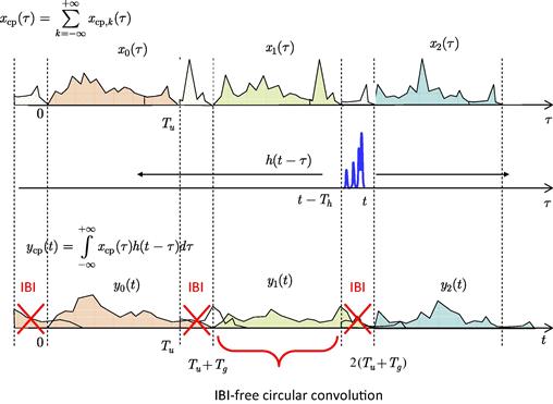
An easy interpretation of CP-OFDM is that the CP induces a circular convolution of the transmitted signal with the CIR, instead of the classical linear convolution. Thus, passing to the digital domain, and after removal of the time guards, the discrete-time received signal during the ![]() th OFDM symbol is expressed by
th OFDM symbol is expressed by
![]() (5.46)
(5.46)
where ![]() is the discrete-time equivalent of the overall CIR, and
is the discrete-time equivalent of the overall CIR, and ![]() stands for the
stands for the ![]() -point discrete circular convolution operator [173]. By well-known DFT properties, the DFT of a time-domain circular convolution of two sequences corresponds to the product of their DFTs, as expressed by
-point discrete circular convolution operator [173]. By well-known DFT properties, the DFT of a time-domain circular convolution of two sequences corresponds to the product of their DFTs, as expressed by
![]() (5.47)
(5.47)
which enables the easy and optimal PSE and detection [251]
![]() (5.48)
(5.48)
![]() (5.49)
(5.49)
The capability to convert any system affected by a frequency-selective channel into a set of ![]() independent flat-fading channels by the insertion of a CP longer than the channel delay spread, is the main motivation for the OFDM success. The main price to be paid is a waste of power efficiency, by a factor equal to
independent flat-fading channels by the insertion of a CP longer than the channel delay spread, is the main motivation for the OFDM success. The main price to be paid is a waste of power efficiency, by a factor equal to ![]() , due to the insertion of
, due to the insertion of ![]() time samples employed for the CP. Additionally, for both CP-OFDM and ZP-OFDM, the CP or ZP insertion to grant IBI-free transmission induces also a data-rate loss, again of a factor
time samples employed for the CP. Additionally, for both CP-OFDM and ZP-OFDM, the CP or ZP insertion to grant IBI-free transmission induces also a data-rate loss, again of a factor ![]() .
.
2.05.6 A vector-matrix representation for OFDM
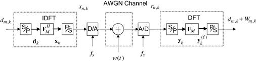
Figure 5.5 shows the discrete-time equivalent model of an OFDM system that exploiting a serial-to-parallel (S/P) converter, selects a block of ![]() data symbols every
data symbols every ![]() seconds, then generates the
seconds, then generates the ![]() discrete-time samples to be transmitted by IDFT processing, and finally, after a parallel-to-serial (P/S) conversion, sends the
discrete-time samples to be transmitted by IDFT processing, and finally, after a parallel-to-serial (P/S) conversion, sends the ![]() samples to a D/A converter. In a vector-matrix notation equivalent to (5.34), the OFDM symbol
samples to a D/A converter. In a vector-matrix notation equivalent to (5.34), the OFDM symbol ![]() transmitted during the
transmitted during the ![]() th period is obtained by
th period is obtained by
![]() (5.50)
(5.50)
where ![]() is a zero-mean uncorrelated data vector with covariance
is a zero-mean uncorrelated data vector with covariance ![]() , and
, and ![]() is the unitary DFT matrix of size
is the unitary DFT matrix of size ![]() . For notational convenience, in (5.50) we have normalized the transmitted samples with respect to
. For notational convenience, in (5.50) we have normalized the transmitted samples with respect to ![]() . In AWGN channels, the received vector
. In AWGN channels, the received vector ![]() is simply expressed by
is simply expressed by
![]() (5.51)
(5.51)
where ![]() , is an i.i.d. zero-mean Gaussian vector with covariance
, is an i.i.d. zero-mean Gaussian vector with covariance ![]() , whose elements
, whose elements ![]() are the samples of the noise
are the samples of the noise ![]() generated by low-pass filtering of
generated by low-pass filtering of ![]() in the A/D converter. Thus, the transmitted data
in the A/D converter. Thus, the transmitted data ![]() can be recovered by a DFT processing that generates the soft estimate
can be recovered by a DFT processing that generates the soft estimate ![]() of the data vector
of the data vector ![]() , as expressed by
, as expressed by
 (5.52)
where ![]() is the
is the ![]() th sample of the unitary DFT of the received vector
th sample of the unitary DFT of the received vector ![]() , and
, and ![]() is a vector containing the frequency-domain samples of the noise, which is still AWGN.
is a vector containing the frequency-domain samples of the noise, which is still AWGN.
The presence of an LTI multipath channel induces a dispersion in time of the symbols transmitted during the ![]() th block, as expressed by
th block, as expressed by
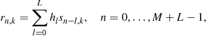 (5.53)
where ![]() is the CIR order, and
is the CIR order, and ![]() for OFDM transmissions. In a vector-matrix notation, this time-domain spreading is captured by the
for OFDM transmissions. In a vector-matrix notation, this time-domain spreading is captured by the ![]() Toeplitz convolution matrix of the channel
Toeplitz convolution matrix of the channel ![]() , which is expressed by
, which is expressed by
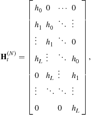 (5.54)
such that a transmitted vector ![]() of size
of size ![]() , generates a received vector
, generates a received vector ![]() , of size
, of size ![]() , as expressed by
, as expressed by
![]() (5.55)
(5.55)
However, because of the channel delay spread ![]() , the received blocks associated to different OFDM blocks overlap in time, thereby generating IBI (see Figure 5.9). As detailed in Section 2.05.3, a simple way to contrast IBI is the introduction of a time guard between OFDM blocks, with a duration
, the received blocks associated to different OFDM blocks overlap in time, thereby generating IBI (see Figure 5.9). As detailed in Section 2.05.3, a simple way to contrast IBI is the introduction of a time guard between OFDM blocks, with a duration ![]() , which can be exploited to insert either zeros as in ZP-OFDM, or the CP as in CP-OFDM. Thus, as shown in Figure 5.12, each transmitted block
, which can be exploited to insert either zeros as in ZP-OFDM, or the CP as in CP-OFDM. Thus, as shown in Figure 5.12, each transmitted block ![]() , of size
, of size ![]() , is expressed by
, is expressed by
![]() (5.56)
(5.56)
where ![]() is the
is the ![]() -size OFDM block before the insertion of the time-guard,
-size OFDM block before the insertion of the time-guard, ![]() with
with ![]() is the
is the ![]() CP insertion matrix for CP-OFDM, and
CP insertion matrix for CP-OFDM, and ![]() is the
is the ![]() ZP insertion matrix for ZP-OFDM. Assuming for simplicity that
ZP insertion matrix for ZP-OFDM. Assuming for simplicity that ![]() , and that the delay spread
, and that the delay spread ![]() of the discrete-time channel is shorter than the OFDM block length
of the discrete-time channel is shorter than the OFDM block length ![]() , the received samples associated to the
, the received samples associated to the ![]() th transmitted symbol can be collected in a vector
th transmitted symbol can be collected in a vector ![]() of size
of size ![]() , as expressed by
, as expressed by
 (5.57)
In (5.57)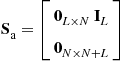 is the
 ![]() matrix that shifts up a vector, inserting zeros in the empty positions, to mimic the time advance associated with the transmission of consecutive OFDM blocks,
matrix that shifts up a vector, inserting zeros in the empty positions, to mimic the time advance associated with the transmission of consecutive OFDM blocks, 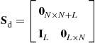 is the
 ![]() matrix that shifts down a vector, inserting zeros in the empty positions, to represent the time delay,
matrix that shifts down a vector, inserting zeros in the empty positions, to represent the time delay, ![]() , and
, and ![]() is the AWGN term.
is the AWGN term.
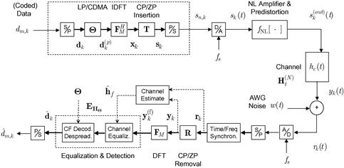
Figure 5.12 Baseband equivalent system model of a LP-OFDM/MC-CDMA system in a multipath fading channel.
2.05.6.1 Vector-matrix representation of CP-OFDM
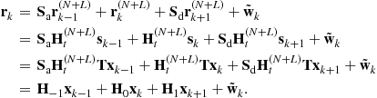
In CP-OFDM, it is straightforward to derive that the structure of the three channel matrices ![]() , is expressed by (5.58). From (5.57) and (5.58), it is clear that the vector
, is expressed by (5.58). From (5.57) and (5.58), it is clear that the vector ![]() , of size
, of size ![]() , suffers from IBI caused by the previous (successive) block only in the first (last)
, suffers from IBI caused by the previous (successive) block only in the first (last) ![]() samples of
samples of ![]() (see also Figure 5.11). Thus, a simple way to remove the IBI is to select only the central
(see also Figure 5.11). Thus, a simple way to remove the IBI is to select only the central ![]() samples of
samples of ![]() : this corresponds to remove the CP and to ignore the last
: this corresponds to remove the CP and to ignore the last ![]() samples induced by the channel delay spread. Note that the last
samples induced by the channel delay spread. Note that the last ![]() samples of
samples of ![]() overlap with the CP of
overlap with the CP of ![]() , which has to be removed as well, because we adopted a receiving window (of length
, which has to be removed as well, because we adopted a receiving window (of length ![]() that overlaps for adjacent blocks.
that overlaps for adjacent blocks.
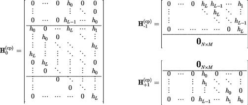 (5.58)
Thus, the received vector typically used for the detection of a CP-OFDM symbol is expressed by
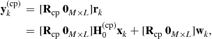 (5.59)
where ![]() is the CP removal matrix defined in [251] for non-overlapping receiving windows. Summarizing, the overall effect of inserting a CP by
is the CP removal matrix defined in [251] for non-overlapping receiving windows. Summarizing, the overall effect of inserting a CP by ![]() , removing it by
, removing it by ![]() , and discarding the last
, and discarding the last ![]() samples, leads to an overall observation equation equal to
samples, leads to an overall observation equation equal to
 (5.60)
where ![]() corresponds to the
corresponds to the ![]() central rows of
central rows of ![]() in (5.58), as expressed by
in (5.58), as expressed by
 (5.61)
The matrix ![]() is circulant, its first column contains the CIR
is circulant, its first column contains the CIR ![]() , and the last equality in (5.61) highlights the equivalence with the notation in [251]. A circulant matrix can be always diagonalized by DFT matrices [89], as expressed by
, and the last equality in (5.61) highlights the equivalence with the notation in [251]. A circulant matrix can be always diagonalized by DFT matrices [89], as expressed by
![]() (5.62)
(5.62)
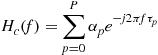
where ![]() is the frequency transfer function of the discrete-time channel, whose
is the frequency transfer function of the discrete-time channel, whose ![]() th element is expressed by (see Figure 5.6)
th element is expressed by (see Figure 5.6)
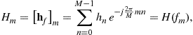 (5.63)
for perfectly band-limited channel models ![]() .
.
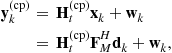
Consequently, taking into account (5.50)
![]() (5.64)
(5.64)
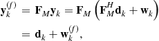
and applying a DFT on the received vector after the CP removal, we obtain
![]() (5.65)
(5.65)
Equation (5.65) highlights that the data transmitted on different subcarriers do not interfere with each other, i.e., there is no ICI, and that the transmitted data are simply scaled by the diagonal frequency-domain channel matrix ![]() . Thus, for a Gaussian white noise
. Thus, for a Gaussian white noise ![]() , the optimal reception based on (5.65) is equivalent to the ML reception based on (5.60), as expressed by [117]
, the optimal reception based on (5.65) is equivalent to the ML reception based on (5.60), as expressed by [117]
 (5.66)
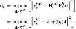
Since the frequency-domain channel matrix is diagonal, (5.66) can be separated in ![]() independent ML decisions
independent ML decisions
 (5.67)
Thus, the ML detector for a CP-OFDM system (that discards the CP) is a per-subcarrier zero-forcing equalizer, followed by a threshold device that selects from the alphabet ![]() the constellation symbol that is closest to the equalizer output
the constellation symbol that is closest to the equalizer output ![]() .
.
2.05.6.2 A note on the CP philosophy
A careful observation of (5.60) and (5.62) reveals that the easy equalization of OFDM is granted by the CP insertion and removal (which produce a circulant channel convolution) rather than by the use of orthogonal subcarriers. Thus, also SC communications could exploit this easy equalization property, by inserting a CP of length ![]() every
every ![]() symbols. This type of block transmission is typically called CP-SC [199,251]. For CP-SC systems, the
symbols. This type of block transmission is typically called CP-SC [199,251]. For CP-SC systems, the ![]() th transmitted block is
th transmitted block is
![]() (5.68)
(5.68)
and, after CP removal by ![]() and DFT processing, the observation vector in the frequency-domain at the receiver side is
and DFT processing, the observation vector in the frequency-domain at the receiver side is
 (5.69)
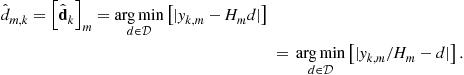
Equation (5.69) also allows for an easy non-ML detection, which consists in a diagonal equalization in the frequency-domain (![]() complex divisions), followed by an IDFT processing and by
complex divisions), followed by an IDFT processing and by ![]() scalar data detections, as expressed by
scalar data detections, as expressed by
![]() (5.70)
(5.70)
where
 (5.71)
where ![]() is the circulant matrix with
is the circulant matrix with ![]() as first column. Note that (5.70) is not the joint ML detector of
as first column. Note that (5.70) is not the joint ML detector of ![]() in (5.69), and that the least-squares (LS) estimator (5.71) is not the linear minimum variance estimator for
in (5.69), and that the least-squares (LS) estimator (5.71) is not the linear minimum variance estimator for ![]() in (5.69). As firstly suggested in [199], and subsequently analyzed in [251,253,254], the CP-SC transmission is the equivalent of the CP-OFDM transmission of Figure 5.5, where also the IDFT processing is moved at the receiver side. Noteworthy, SC block transmission could induce a circulant convolution, and exploit diagonal frequency-domain equalization, also by substituting the CP with a known symbol [46] that can be further exploited for channel estimation and synchronization purposes.
in (5.69). As firstly suggested in [199], and subsequently analyzed in [251,253,254], the CP-SC transmission is the equivalent of the CP-OFDM transmission of Figure 5.5, where also the IDFT processing is moved at the receiver side. Noteworthy, SC block transmission could induce a circulant convolution, and exploit diagonal frequency-domain equalization, also by substituting the CP with a known symbol [46] that can be further exploited for channel estimation and synchronization purposes.
2.05.6.3 Vector-matrix representation of ZP-OFDM
For ZP-OFDM, the three channel matrices ![]() and
and ![]() in (5.57) are expressed by (5.72). Thanks to the insertion of zeros among the blocks, the received vector
in (5.57) are expressed by (5.72). Thanks to the insertion of zeros among the blocks, the received vector ![]() does not contain any IBI (see also Figure 5.10). The useful information about the data
does not contain any IBI (see also Figure 5.10). The useful information about the data ![]() transmitted during the
transmitted during the ![]() th block is contained in the first
th block is contained in the first ![]() samples.
samples.
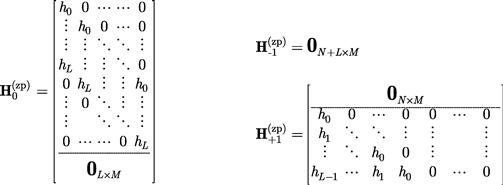 (5.72)
Therefore, in order to recover the data, it is sufficient to employ a receiving window of size ![]() to collect
to collect
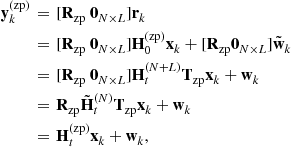 (5.73)
where the receiving matrix for ZP-OFDM is simply expressed by ![]() , and
, and ![]() contains the first
contains the first ![]() rows of
rows of ![]() . In (5.73), the last-but-one equality highlights the equivalence with the notation used in [251]. Summarizing, the ZP-OFDM transmission through a time-dispersive channel is affected by the banded Toeplitz channel matrix
. In (5.73), the last-but-one equality highlights the equivalence with the notation used in [251]. Summarizing, the ZP-OFDM transmission through a time-dispersive channel is affected by the banded Toeplitz channel matrix ![]() , contained in the first
, contained in the first ![]() rows of
rows of ![]() in (5.72), which has always full rank. In this case, the channel matrix is not circulant, and the received vector has a size
in (5.72), which has always full rank. In this case, the channel matrix is not circulant, and the received vector has a size ![]() . Thus, a receiver that employs a pure DFT operation should use a DFT matrix
. Thus, a receiver that employs a pure DFT operation should use a DFT matrix ![]() of size
of size ![]() , which would correspond to project the received vector on a set of discrete frequencies different from those used at the transmitter side, which does not make any sense. The intuition would suggest to use, at the receiver side, the same discrete frequencies
, which would correspond to project the received vector on a set of discrete frequencies different from those used at the transmitter side, which does not make any sense. The intuition would suggest to use, at the receiver side, the same discrete frequencies ![]() used at the transmitter (which are periodic), by extending them on the longer time-support
used at the transmitter (which are periodic), by extending them on the longer time-support ![]() . This corresponds to use a set of basis functions contained in the columns of the matrix
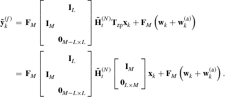
. This corresponds to use a set of basis functions contained in the columns of the matrix
![]() (5.74)
(5.74)
where ![]() is the
is the ![]() matrix containing the first
matrix containing the first ![]() columns of
columns of ![]() , to extend each basis vector. Thus, projecting the received vector onto the extended basis, we obtain
, to extend each basis vector. Thus, projecting the received vector onto the extended basis, we obtain
 (5.75)
where ![]() is a shortened version of
is a shortened version of ![]() to its first
to its first ![]() values, and
values, and ![]() is an
is an ![]() vector containing an anticipated version of
vector containing an anticipated version of ![]() , with its last
, with its last ![]() samples in the first
samples in the first ![]() positions, and zeros elsewhere. Thus, (5.75) is the vector-matrix equivalent of (5.40) and (5.41), which enabled in ZP-OFDM the simple PSE and decoding of the data transmitted on each separate subcarrier
positions, and zeros elsewhere. Thus, (5.75) is the vector-matrix equivalent of (5.40) and (5.41), which enabled in ZP-OFDM the simple PSE and decoding of the data transmitted on each separate subcarrier ![]() . Indeed, plugging (5.73) in (5.75), we obtain
. Indeed, plugging (5.73) in (5.75), we obtain
 (5.76)
By direct substitution, it is straightforward to prove that
 (5.77)
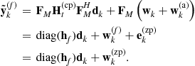 (5.78)
Note that, except for the extra noise term ![]() induced by the anticipated replica
induced by the anticipated replica ![]() , (5.78) is equivalent to the receiving Eq. (5.65) for CP-OFDM, and consequently simple PSE is possible also in this case. However, PSE and detection by (5.67) would not result in the ML estimator of
, (5.78) is equivalent to the receiving Eq. (5.65) for CP-OFDM, and consequently simple PSE is possible also in this case. However, PSE and detection by (5.67) would not result in the ML estimator of ![]() in (5.78), because
in (5.78), because ![]() is characterized by a (non-diagonal) circulant correlation matrix, expressed by
is characterized by a (non-diagonal) circulant correlation matrix, expressed by
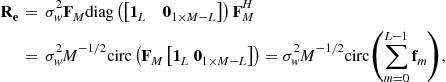
which introduces a color on the overall noise ![]() [117]. Indeed, in this case, the ML estimator of
[117]. Indeed, in this case, the ML estimator of ![]() in (5.78), with a perfect channel knowledge, would request to compute
in (5.78), with a perfect channel knowledge, would request to compute
 (5.79)
that reduces to
![]() (5.80)
(5.80)
only if the noise is white and uncorrelated, that is if ![]() is a scaled identity matrix, which is not this case since
is a scaled identity matrix, which is not this case since ![]() .
.
2.05.7 Symbol error rate (SER) performance analysis
The SER analysis for ML detection of CP-OFDM is quite simple, because of the frequency-domain channel diagonalization induced by the CP. Indeed, (5.65) and (5.45) show that the data transmitted on each separate subcarrier are impaired by a flat-fading channel, as expressed by
![]() (5.81)
(5.81)
If the discrete-time channel taps ![]() are zero-mean Gaussian distributed, then it is straightforward to verify that
are zero-mean Gaussian distributed, then it is straightforward to verify that ![]() in (5.63) is also zero-mean Gaussian,
in (5.63) is also zero-mean Gaussian, ![]() is Rayleigh distributed with a probability density function (pdf) expressed by
is Rayleigh distributed with a probability density function (pdf) expressed by ![]() , with
, with ![]() , and
, and
 (5.82)
where ![]() is the autocorrelation matrix of the discrete-time channel, and
is the autocorrelation matrix of the discrete-time channel, and ![]() is the AWGN in the frequency-domain. Thus, the symbol error rate (SER) performance on a frequency-flat Rayleigh fading channel for each subcarrier is expressed by [183]
is the AWGN in the frequency-domain. Thus, the symbol error rate (SER) performance on a frequency-flat Rayleigh fading channel for each subcarrier is expressed by [183]
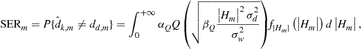 (5.83)
where ![]() and
and ![]() depend on the complex alphabet
depend on the complex alphabet ![]() of
of ![]() . Defining the average SNR for each subcarrier as
. Defining the average SNR for each subcarrier as ![]() , if
, if ![]() is drawn from a QPSK alphabet, (5.83) leads to [183]
is drawn from a QPSK alphabet, (5.83) leads to [183]
 (5.84)
and the total ![]() is the average of (5.84) over all the subcarriers, as expressed by
is the average of (5.84) over all the subcarriers, as expressed by
 (5.85)
Equation (5.84), together with (5.82), highlights that the SER performance depends on the sum of the second order moments of the time-domain channel paths rather than on the number ![]() of the paths. For instance, in the simpler case when the channel paths are independents (i.e.,
of the paths. For instance, in the simpler case when the channel paths are independents (i.e., ![]() , (5.82) becomes
, (5.82) becomes
 (5.86)
which highlights the two following observations:
i. ![]() , and consequently
, and consequently ![]() , is the same for all the subcarriers, and
, is the same for all the subcarriers, and ![]() .
.
ii. The ![]() depends only on the total power
depends only on the total power ![]() of the multipath channel and does not depend on the power distribution among the different paths (i.e., does not depend on the power-delay profile of the channel). Thus, the performance of CP-OFDM in a multipath Rayleigh fading channel would be the same performance in a single-path Rayleigh fading channel, where all the power is concentrated in the single path.
of the multipath channel and does not depend on the power distribution among the different paths (i.e., does not depend on the power-delay profile of the channel). Thus, the performance of CP-OFDM in a multipath Rayleigh fading channel would be the same performance in a single-path Rayleigh fading channel, where all the power is concentrated in the single path.
The last observation indicates that an uncoded CP-OFDM system is not capable to exploit the potential diversity offered by a multipath fading channel. Indeed, while it is highly improbable that all the ![]() time-domain paths fade to zero simultaneously, the single frequency-domain path associated to each data in (5.81) has a greater probability to fade towards zero, making the data
time-domain paths fade to zero simultaneously, the single frequency-domain path associated to each data in (5.81) has a greater probability to fade towards zero, making the data ![]() unrecoverable also in the presence of a low noise value
unrecoverable also in the presence of a low noise value ![]() . Actually, each single path of the CIR is a potential source of diversity,2 because the receiver collects multiple (independent) copies of the transmitted signal. This is similar to the space diversity offered by multi-antenna receiving systems [183]. However, the CP insertion and removal, which leads to the frequency-domain channel diagonalization, destroys the multipath diversity and sacrifices uncoded SER performance for a simpler per-subcarrier equalization. Such loss of diversity for uncoded SER performance can be recovered by channel coding (see Section 2.05.6), or by linear precoding (see Section 2.05.7), which spreads each uncoded data over all (or several) different subcarriers [167]. The SER analysis for ML decoding of ZP-OFDM is not as simple as for CP-OFDM, because the ML detection based on (5.73) leads to
. Actually, each single path of the CIR is a potential source of diversity,2 because the receiver collects multiple (independent) copies of the transmitted signal. This is similar to the space diversity offered by multi-antenna receiving systems [183]. However, the CP insertion and removal, which leads to the frequency-domain channel diagonalization, destroys the multipath diversity and sacrifices uncoded SER performance for a simpler per-subcarrier equalization. Such loss of diversity for uncoded SER performance can be recovered by channel coding (see Section 2.05.6), or by linear precoding (see Section 2.05.7), which spreads each uncoded data over all (or several) different subcarriers [167]. The SER analysis for ML decoding of ZP-OFDM is not as simple as for CP-OFDM, because the ML detection based on (5.73) leads to
![]() (5.87)
(5.87)
which does not have an equivalent (diagonal) formulation in the frequency-domain, because of the banded Toeplitz structure of ![]() . Consequently, differently from CP-OFDM, the ML detector for ZP-OFDM is not based on PSE. SER and diversity analysis for ML problems like in (5.87) are typically addressed by the probability that a given transmitted data vector
. Consequently, differently from CP-OFDM, the ML detector for ZP-OFDM is not based on PSE. SER and diversity analysis for ML problems like in (5.87) are typically addressed by the probability that a given transmitted data vector ![]() is confused at the receiver side with another possible transmitted vector
is confused at the receiver side with another possible transmitted vector ![]() . This leads to the so-called pairwise-error probability (PEP) [218,219,229,236], which is defined as
. This leads to the so-called pairwise-error probability (PEP) [218,219,229,236], which is defined as
![]() (5.88)
(5.88)
and dominates the SER. As detailed in [250], the minimum PEP for all the possible couples ![]() is granted if the observation matrix
is granted if the observation matrix ![]() has a full column rank for any channel realization. This is equivalent to state that, in the absence of noise, is not possible to confuse
has a full column rank for any channel realization. This is equivalent to state that, in the absence of noise, is not possible to confuse ![]() with
with ![]() at the receiver, or equivalently, to the symbol detectability condition [251]
at the receiver, or equivalently, to the symbol detectability condition [251]
![]() (5.89)
(5.89)
Actually, (5.89) is granted because both ![]() and
and ![]() are always full column rank, and consequently
are always full column rank, and consequently ![]() . The same analysis for CP-OFDM highlights that the observation matrix in (5.66) is
. The same analysis for CP-OFDM highlights that the observation matrix in (5.66) is ![]() , which is not full rank for those channel realizations
, which is not full rank for those channel realizations ![]() that contain a zero in one of its elements. Indeed, in CP-OFDM, if the discrete-time channel
that contain a zero in one of its elements. Indeed, in CP-OFDM, if the discrete-time channel ![]() induces a frequency-domain channel
induces a frequency-domain channel ![]() with a zero on the
with a zero on the ![]() th subcarrier, i.e.,
th subcarrier, i.e., ![]() , the data
, the data ![]() on that subcarrier would be not recoverable even in the absence of noise, as clarified by (5.81). Thus, at the receiver side, those data vectors
on that subcarrier would be not recoverable even in the absence of noise, as clarified by (5.81). Thus, at the receiver side, those data vectors ![]() that differ from
that differ from ![]() only on the
only on the ![]() th element would be undistinguishable from
th element would be undistinguishable from ![]() , causing a degradation of the average PEP and SER.
, causing a degradation of the average PEP and SER.
The price paid by ZP-OFDM with respect to CP-OFDM, for better uncoded SER performance with ML detection, is the higher detection complexity induced by (5.87), which grows exponentially with the vector size ![]() and the cardinality of the data alphabet
and the cardinality of the data alphabet ![]() . Conversely, if ZP-OFDM is detected by exploiting the overlap-and-add (OLA) approach of (5.75), the detection complexity is significantly reduced. Indeed, the OLA operation of (5.75) induces a circulant channel at the receiver side: in this case, a simpler PSE can be employed by compensating for the
. Conversely, if ZP-OFDM is detected by exploiting the overlap-and-add (OLA) approach of (5.75), the detection complexity is significantly reduced. Indeed, the OLA operation of (5.75) induces a circulant channel at the receiver side: in this case, a simpler PSE can be employed by compensating for the ![]() term in (5.78). Therefore, OLA-based per-subcarrier detection of ZP-OFDM presents a decoding complexity
term in (5.78). Therefore, OLA-based per-subcarrier detection of ZP-OFDM presents a decoding complexity ![]() that is similar to CP-OFDM. In addition, using OLA-based per-subcarrier detection of ZP-OFDM, also the SER performance would be somewhat similar to CP-OFDM (see Figure 5.13). Indeed, with respect to CP-OFDM, OLA-based ZP-OFDM presents a noise power penalty caused by the extra noise term
that is similar to CP-OFDM. In addition, using OLA-based per-subcarrier detection of ZP-OFDM, also the SER performance would be somewhat similar to CP-OFDM (see Figure 5.13). Indeed, with respect to CP-OFDM, OLA-based ZP-OFDM presents a noise power penalty caused by the extra noise term ![]() in (5.78), and an equivalent advantage on the average (useful) signal power due to the absence of CP transmission. Each of these two effects compensates with one another, as shown in Figure 5.13.
in (5.78), and an equivalent advantage on the average (useful) signal power due to the absence of CP transmission. Each of these two effects compensates with one another, as shown in Figure 5.13.
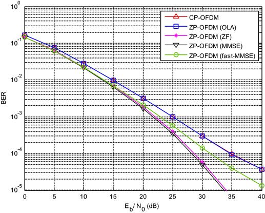
Figure 5.13 Performance comparison between CP-OFDM and different ZP-OFDM detectors in a multipath Rayleigh fading channel (Uncoded BER, QPSK, ![]() ,
, ![]() , Channel A of HIPERLAN/2). This figure has been generated using the MATLAB script zp_vs_cp.m.
, Channel A of HIPERLAN/2). This figure has been generated using the MATLAB script zp_vs_cp.m.
2.05.7.1 Suboptimal linear equalization/detection for ZP-OFDM
As detailed in [167], other suboptimal receivers for ZP-OFDM are possible, allowing for different performance-complexity trade-offs. For instance, linear receivers produce a soft estimate of the transmitted data by
![]() (5.90)
(5.90)
where the equalization/detection matrix can be designed according to a LS or MMSE approach [117], as expressed by
![]() (5.91)
(5.91)
and
![]() (5.92)
(5.92)
It is clear from (5.91) and (5.92), that this approach consists in a LS and MMSE equalization of the tall and Toeplitz channel matrix ![]() in (5.73), followed by a frequency-domain per subcarrier detection.
in (5.73), followed by a frequency-domain per subcarrier detection.
These LS and MMSE approaches, denoted in Figure 5.13 with ZF and MMSE, respectively, give a performance gain with respect to OLA-based detection, at the price of increased complexity, which is ![]() .
.
Another low-complexity suboptimal approach, denoted with fast-MMSE in Figure 5.13, relies on a sliding window of dimension ![]() that includes two ZP parts: the ZP part that precedes, and the ZP part that follows, the data vector of size
that includes two ZP parts: the ZP part that precedes, and the ZP part that follows, the data vector of size ![]() . In this case, the first ZP part, of size
. In this case, the first ZP part, of size ![]() , can be interpreted as the CP of the remaining vector, of size
, can be interpreted as the CP of the remaining vector, of size ![]() , because the last part of the remaining vector is the second ZP part. As a consequence, the detection approach can be similar to CP-OFDM: the first ZP part is discarded, and the FFT of size
, because the last part of the remaining vector is the second ZP part. As a consequence, the detection approach can be similar to CP-OFDM: the first ZP part is discarded, and the FFT of size ![]() is applied on the remaining vector of size
is applied on the remaining vector of size ![]() . The complexity of this fast-MMSE approach is
. The complexity of this fast-MMSE approach is ![]() .
.
2.05.8 Coded—OFDM
As highlighted in Section 2.05.5, and summarized by (5.81) and (5.83), CP-OFDM is not capable to exploit the potential diversity offered by a multipath fading channel, whose taps fade in an independent fashion. This is a direct consequence of transmitting each single data ![]() onto a single subcarrier: if the
onto a single subcarrier: if the ![]() th frequency channel
th frequency channel ![]() fades to zero, there is no way to recover
fades to zero, there is no way to recover ![]() , because
, because ![]() is not contained in any other diversely received sample. Thus, in highly frequency-selective channels, the SER performance is significantly degraded because of the loss of the data
is not contained in any other diversely received sample. Thus, in highly frequency-selective channels, the SER performance is significantly degraded because of the loss of the data ![]() on those subcarriers that are impaired by an almost null channel transfer function. For instance, in multipath Rayleigh fading conditions, the SER performance is equivalent to that of a single-carrier system impaired by a Rayleigh flat-fading channel, with diversity order equal to one.
on those subcarriers that are impaired by an almost null channel transfer function. For instance, in multipath Rayleigh fading conditions, the SER performance is equivalent to that of a single-carrier system impaired by a Rayleigh flat-fading channel, with diversity order equal to one.
Possible counter-measures to channel fading are typically known as diversity techniques and historically emerged in telecommunications by providing the receiver with multiple copies of the same information. These multiple copies of the same information are transmitted in the frequency-domain [or in the space (antenna)-domain or in the time-domain], and possibly are impaired by independent fading distortions [183]. The correct combination of multiple information manifests in an increase of the average SNR, a better SNR statistic, and consequently a SER performance that tends to the SER in AWGN channels, when the number of independent information copies is high enough [183]. Anyway, a pure diversity technique cannot improve performance over the SER threshold represented by the AWGN scenario.
Actually, Forward Error Correcting codes (FECs), or channel codes, were historically designed to contrast the errors in AWGN scenarios, by introducing algebraically-structured redundancy [183]. This form of redundancy, introduced at the transmitter side, distributes the information data on almost all the subcarriers: consequently, by channel decoding at the receiver side, it is possible to exploit this redundancy to jointly contrast the errors induced by fading channels and collect part of the channel diversity. Some examples of popular FEC schemes [183] exploited in standard Coded-OFDM (C-OFDM) systems include block-codes (e.g., Reed-Solomon codes), convolutional codes (CC), and concatenated codes, which were exploited since the beginning of the OFDM era in commercial systems such as DAB [71], DVB-T/S [72], WiFi [104], WiMAX [105], while BCH codes, turbo codes and low-density parity-check (LDPC) codes [183] have been more recently exploited in DVB-T2/S2 [73] and UMTS-LTE [237].
The basic idea to use FEC to contrast fading is to make the errors statistic induced by fading looks similar to the error statistic introduced by the noise in AWGN channels: this is obtained by equipping the OFDM system with appropriate interleavers, which scramble the coded data through the subcarriers to collect the channel frequency diversity, and through consecutive OFDM blocks to collect the channel time diversity. The price for such a joint resistance to fading and AWGN is the increase of decoding delay, because the interleaver depth may span several OFDM blocks in order to be effective. Thus, especially for time-sensitive communications, it could be preferable to have some sort of diversity resistance that does not require coding over several consecutive OFDM blocks.
This possibility has been explored more recently, by exploiting the possibility to transmit (possibly redundant) linear combinations of the data ![]() by the so called linearly precoded-OFDM (see Section 2.05.9), or by antenna-diversity through space-time coding (see [66,84,88,178] ad references therein for further details).
by the so called linearly precoded-OFDM (see Section 2.05.9), or by antenna-diversity through space-time coding (see [66,84,88,178] ad references therein for further details).
2.05.9 Linearly precoded-OFDM (LP-OFDM)
FEC are typically designed to contrast AWGN channels and therefore are designed in order to maximize the Euclidean distance among codewords in order to be resistant to an additive distortion. This Euclidean maximization is not the optimal strategy in a fading channel, where the Hamming distance is the key element to minimize the PEP among codewords [229,250], in order to be resistant to a multiplicative Distortion.
In an OFDM system, which conveys information on parallel carriers, the transmitter could spread a group of data ![]() over several of these carriers, by exploiting a linear precoding (LP) matrix
over several of these carriers, by exploiting a linear precoding (LP) matrix ![]() . The aim is to introduce frequency diversity and potentially be capable to recover all the transmitted data (exploiting the finite alphabet of
. The aim is to introduce frequency diversity and potentially be capable to recover all the transmitted data (exploiting the finite alphabet of ![]() even if one of the carriers fades to zero. Thus, an LP transmitter generates a (potentially redundant) vector
even if one of the carriers fades to zero. Thus, an LP transmitter generates a (potentially redundant) vector ![]() by performing a linear combination of the original data, as shown in Figure 5.12 and expressed by
by performing a linear combination of the original data, as shown in Figure 5.12 and expressed by
![]() (5.93)
(5.93)
where ![]() , is the (possibly redundant) precoding matrix3 of size
, is the (possibly redundant) precoding matrix3 of size ![]() . Thus, with LP, a CP-OFDM system transmits
. Thus, with LP, a CP-OFDM system transmits ![]() through a multipath fading channel
through a multipath fading channel ![]() , and (5.65) becomes
, and (5.65) becomes
![]() (5.94)
(5.94)
where the number of subcarriers (i.e., the size of ![]() and
and ![]() ) is
) is ![]() . From (5.94), ML detection requests to compute
. From (5.94), ML detection requests to compute
![]() (5.95)
(5.95)
which involves the non-diagonal channel-precoding matrix ![]() . Thus, the easy PSE (and easy ML detection) of OFDM is lost, but the PEP (and SER) performance can be boosted by a proper design of the precoding matrix
. Thus, the easy PSE (and easy ML detection) of OFDM is lost, but the PEP (and SER) performance can be boosted by a proper design of the precoding matrix ![]() .
.
As clarified in [172], in order to exploit all the diversity ![]() offered by a multipath fading channel, the overall observation matrix should guarantee that in the absence of noise any couple of transmitted data vectors are observable at the receiver side with a minimum Hamming distance greater than or equal to
offered by a multipath fading channel, the overall observation matrix should guarantee that in the absence of noise any couple of transmitted data vectors are observable at the receiver side with a minimum Hamming distance greater than or equal to ![]() . To this end, it is sufficient (but not necessary) to guarantee the symbol detectability condition, i.e., that
. To this end, it is sufficient (but not necessary) to guarantee the symbol detectability condition, i.e., that ![]() has full column rank. Note that the discrete-time frequency response
has full column rank. Note that the discrete-time frequency response ![]() of a time-domain channel
of a time-domain channel ![]() with
with ![]() non-zero paths may have at most
non-zero paths may have at most ![]() zeros: therefore,
zeros: therefore, ![]() can cancel-out up to
can cancel-out up to ![]() rows of
rows of ![]() . Thus, it would be enough to redundantly design
. Thus, it would be enough to redundantly design ![]() with
with ![]() linearly independent rows, such that any set of
linearly independent rows, such that any set of ![]() rows of
rows of ![]() are linearly independent. If this design condition is verified, the row cancellation in
are linearly independent. If this design condition is verified, the row cancellation in ![]() still guarantee that
still guarantee that ![]() has (full-column) rank
has (full-column) rank ![]() . Thus, by the
. Thus, by the ![]() out of
out of ![]() observations in (5.94) that are different from zero, it would be always possible in the absence of noise to distinguish any transmitted data vector
observations in (5.94) that are different from zero, it would be always possible in the absence of noise to distinguish any transmitted data vector ![]() from any other
from any other ![]() . A possible choice for such precoding matrices are Vandermonde matrices where [251]
. A possible choice for such precoding matrices are Vandermonde matrices where [251]
![]() (5.96)
(5.96)
or cosine matrices with
![]() (5.97)
(5.97)
When ![]() and
and ![]() , the Vandermonde matrix becomes the DFT matrix
, the Vandermonde matrix becomes the DFT matrix ![]() , while, when
, while, when ![]()
![]() represents the discrete cosine transform (DCT) matrix. Moreover, note that the precoding matrix should be normalized such that all the columns have a unit norm, i.e.,
represents the discrete cosine transform (DCT) matrix. Moreover, note that the precoding matrix should be normalized such that all the columns have a unit norm, i.e., ![]() [250] in order to not decrease the minimum Euclidean distance between the precoded vectors and consequently penalize the SER performance in AWGN channels where
[250] in order to not decrease the minimum Euclidean distance between the precoded vectors and consequently penalize the SER performance in AWGN channels where ![]() .
.
An interesting choice for the redundant precoding matrix is ![]() , i.e., the Vandermonde matrix obtained by selecting the first
, i.e., the Vandermonde matrix obtained by selecting the first ![]() columns of an IDFT matrix of size
columns of an IDFT matrix of size ![]() . By this choice, the precoded vector to be transmitted, is expressed by
. By this choice, the precoded vector to be transmitted, is expressed by
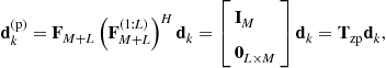 (5.98)
which is nothing else than a ZP-SC system, which does not need the use of a CP. Thus, the redundancy introduced by ZP in a block SC system grants not only IBI suppression, but also symbol detectability and, consequently, the capability by ML decoding to exploit the maximum diversity offered by the channel [253,254].
In practice, LP-OFDM systems (including ZP-SC), can capture (part of) the diversity [236] also by exploiting suboptimal linear equalization/detection schemes by producing the soft estimate
![]() (5.99)
(5.99)
where the equalization/detection matrix ![]() can be computed by an LS or MMSE approach [117], by substituting
can be computed by an LS or MMSE approach [117], by substituting ![]() with
with ![]() in (5.91) and (5.92), respectively. Further details can be found in [250].
in (5.91) and (5.92), respectively. Further details can be found in [250].
However, the sufficient condition ![]() guarantees that any couple of vectors
guarantees that any couple of vectors ![]() could be distinguished at the receiver side in the absence of noise, without exploiting the fact that the elements of
could be distinguished at the receiver side in the absence of noise, without exploiting the fact that the elements of ![]() belong to a finite alphabet
belong to a finite alphabet ![]() . Thus, by exploiting the structure imposed on the possible data vectors by the finite alphabet and algebraic number theory, it is possible to design also non-redundant (square) precoding matrices
. Thus, by exploiting the structure imposed on the possible data vectors by the finite alphabet and algebraic number theory, it is possible to design also non-redundant (square) precoding matrices ![]() that are capable to capture all the diversity offered by the channel, with
that are capable to capture all the diversity offered by the channel, with ![]() . As detailed in [148], such a matrix is proved to always exist: it is a square Vandermonde matrix, whose elements are expressed by
. As detailed in [148], such a matrix is proved to always exist: it is a square Vandermonde matrix, whose elements are expressed by
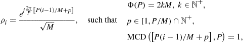 (5.100)
where ![]() is the Euler’s totient function, which identifies the number of integers that are lower, and relative prime, with respect to
is the Euler’s totient function, which identifies the number of integers that are lower, and relative prime, with respect to ![]() . Although for a given size
. Although for a given size ![]() the solution of (5.100) is not unique, for the special but important case where
the solution of (5.100) is not unique, for the special but important case where ![]() is a power of two, the precoding matrix can be always written as
is a power of two, the precoding matrix can be always written as
![]() (5.101)
(5.101)
which highlights that the precoding matrix is unitary, i.e., ![]() . Moreover, (5.101) practically states that the diversity-optimum CP-aided block transmission, is a CP-SC system equipped by a simple diagonal non-redundant precoder, as expressed by the transmitted data vector
. Moreover, (5.101) practically states that the diversity-optimum CP-aided block transmission, is a CP-SC system equipped by a simple diagonal non-redundant precoder, as expressed by the transmitted data vector
![]() (5.102)
(5.102)
It is important to highlight that the non redundant precoding based on (5.100) or (5.101) is not only capable to capture all the diversity, but can also maximize the coding gain4 in SER performance, by selecting the lowest ![]() that satisfies (5.100). For further details on optimal constellation rotations, the interested readers are redirected to [24,32,87].
that satisfies (5.100). For further details on optimal constellation rotations, the interested readers are redirected to [24,32,87].
The price to be paid for the exploitation of the channel diversity is the computational complexity of ML decoding, which grows exponentially with the size ![]() of the data vector
of the data vector ![]() . Quasi-ML decoding performance can be obtained by algorithms such as sphere decoding [250] characterized by reduced complexity for moderate precoder sizes and many SNR values [108].
. Quasi-ML decoding performance can be obtained by algorithms such as sphere decoding [250] characterized by reduced complexity for moderate precoder sizes and many SNR values [108].
However, it can be observed that, in order to not sacrifice too much the system efficiency, the CP or ZP length is in general ![]() , and consequently, in order to collect the diversity
, and consequently, in order to collect the diversity ![]() offered by the channel, it would be enough to spread each symbol on a number of subcarriers
offered by the channel, it would be enough to spread each symbol on a number of subcarriers ![]() , where
, where ![]() is an integer greater than 1. Therefore, instead of a large precoder of size
is an integer greater than 1. Therefore, instead of a large precoder of size ![]() equal to the number of subcarriers, many precoders can be applied to different groups of
equal to the number of subcarriers, many precoders can be applied to different groups of ![]() subcarriers. This corresponds to an overall precoded matrix that can be written as
subcarriers. This corresponds to an overall precoded matrix that can be written as
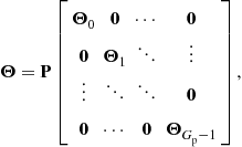 (5.103)
where ![]() is a permutation matrix that establishes how the
is a permutation matrix that establishes how the ![]() subcarriers are grouped into the
subcarriers are grouped into the ![]() groups, and
groups, and ![]() is a
is a ![]() non-redundant precoding matrix designed according to (5.101). Since the benefit in SER performance tends to reduce for increasing diversity [183], suboptimal designs based on (5.103) with
non-redundant precoding matrix designed according to (5.101). Since the benefit in SER performance tends to reduce for increasing diversity [183], suboptimal designs based on (5.103) with ![]() can be employed: this way, the ML decoding in (5.95) leads to
can be employed: this way, the ML decoding in (5.95) leads to ![]() parallel ML decoding problems for the data observed (and transmitted) on the
parallel ML decoding problems for the data observed (and transmitted) on the ![]() orthogonal sets, with a complexity
orthogonal sets, with a complexity ![]() instead of
instead of ![]() . The parallel ML decoding is expressed by
. The parallel ML decoding is expressed by
 (5.104)
The data sub-vectors ![]() , as well as the other quantities in (5.104), are just the sub-vectors selected from the corresponding ones in (5.95), by means of (5.103). This approach has been proposed in [148], where it is called grouped linear precoding (GLP). In order to collect the highest possible diversity for all the subgroups, and thus optimize the average SER, the best strategy is to design the permutation matrix
, as well as the other quantities in (5.104), are just the sub-vectors selected from the corresponding ones in (5.95), by means of (5.103). This approach has been proposed in [148], where it is called grouped linear precoding (GLP). In order to collect the highest possible diversity for all the subgroups, and thus optimize the average SER, the best strategy is to design the permutation matrix ![]() such that each subgroups of data
such that each subgroups of data ![]() is assigned to a different set of equispaced subcarriers, which, being separated, are most likely different (more diverse) than contiguous subcarriers [148]. In the context of non-redundant GLP-OFDM, the performance of ML and other suboptimal equalization/detection schemes, such as ZF and MMSE, is shown in Figure 5.14.
is assigned to a different set of equispaced subcarriers, which, being separated, are most likely different (more diverse) than contiguous subcarriers [148]. In the context of non-redundant GLP-OFDM, the performance of ML and other suboptimal equalization/detection schemes, such as ZF and MMSE, is shown in Figure 5.14.

Figure 5.14 Performance comparison among different detection criteria for GLP-OFDM (Uncoded BER, BPSK,![]() ,
,![]() ,
, ![]() ,
, ![]() , multipath channel with uniform power-delay profile). This figure has been generated using the MATLAB script lp_ofdm.m.
, multipath channel with uniform power-delay profile). This figure has been generated using the MATLAB script lp_ofdm.m.
Linear precoding approaches for multicarrier transmissions have been discussed also in [38], which compares linear precoders based on rotated (Fourier or Walsh-Hadamard) transforms, and in [146], which derives the conditions for minimum-SER precoding design for a linear detector.
A fundamental contribution to redundant LP can be found in [201,202]. The first of these two companion papers generalizes OFDM, DMT, CDMA, and TDMA communications, and establishes sufficient conditions for a precoded transmission scheme to perfectly equalize any FIR channel (channel identifiability), independently of its zeros locations. Additionally, a joint ZF design of the transmitter and receiver filterbanks is proposed, under MMSE and maximum SNR criteria. The second paper, by a ZP approach, derives also blind channel estimators, block synchronizers, and direct-equalizers for the proposed filterbank structure. Note that, also multiuser MC systems, such those addressed in the next section, fall within the general filterbank formulation in [201,202].
As a final remark, it should be noted that LP and FEC are not alternative with one another, but they are both valuable tools to protect an OFDM system from errors induced by a fading channel. As already explained, FECs have been historically introduced to protect digital communications from AWGN, they introduce redundancy, and can be effective also to combat channel fading by properly scrambling and interleaving the coded data. Conversely, LP techniques are designed to exploit the channel diversity (if it is present), cannot improve performance in AWGN, and they do not necessarily request redundancy. Thus, a proper design could combine LP with FEC, in order to collect the channel diversity (if any) to make the equivalent channel almost AWGN, and then exploit FEC mainly to protect from AWGN. In severe multipath fading channels, this approach can guarantee SER performance equivalent to those of a pure FEC-OFDM system, with lower redundancy, lower complexity, and lower decoding delay. Readers interested on a comparison of LP with FEC, and on their joint design, are redirected to [252–254].
2.05.10 Multiuser multicarrier systems
Section 2.05.2 has clarified that OFDM can be seen as a special case of CDMA, where ![]() parallel data flows are simultaneously transmitted in time and distinguished by the use of different codes
parallel data flows are simultaneously transmitted in time and distinguished by the use of different codes ![]() , as expressed by
, as expressed by
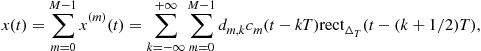 (5.105)
where ![]() is the symbol period and
is the symbol period and ![]() is the symbol duration, less than or equal to the symbol period. For instance, a CDMA system with
is the symbol duration, less than or equal to the symbol period. For instance, a CDMA system with ![]() parallel transmissions, can be represented during the useful
parallel transmissions, can be represented during the useful ![]() th symbol by a transmitted data vector
th symbol by a transmitted data vector ![]() expressed by
expressed by
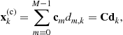 (5.106)
where ![]() , with
, with ![]() , is the
, is the ![]() th spreading sequence, also known as spreading code, and
th spreading sequence, also known as spreading code, and ![]() is the code matrix. Additionally, to handle IBI as in OFDM transmissions, each transmitted block in (5.105) could be separated in time by
is the code matrix. Additionally, to handle IBI as in OFDM transmissions, each transmitted block in (5.105) could be separated in time by ![]() , leading to a CP-CDMA when
, leading to a CP-CDMA when ![]() , or to a ZP-CDMA when
, or to a ZP-CDMA when ![]() . Further considerations on CDMA are left for the end of this section where CDMA systems are briefly compared with multiuser MC systems.
. Further considerations on CDMA are left for the end of this section where CDMA systems are briefly compared with multiuser MC systems.
In the case of OFDM, the codes are ![]() , which are orthogonal on the useful duration
, which are orthogonal on the useful duration ![]() by (21),
by (21), ![]() , and the overall transmitted block is
, and the overall transmitted block is
 (5.107)
with ![]() for CP-OFDM and
for CP-OFDM and ![]() for ZP-OFDM. When orthogonal frequencies
for ZP-OFDM. When orthogonal frequencies ![]() are employed to distinguish different users, the system is identified as an OFDM access (OFDMA) systems, which has the nice property to preserve users’ orthogonality in LTI channels. Moreover, different data rates can be easily handled in OFDMA by reserving different groups of subcarriers to different users, as it happens for instance in WiMAX and LTE [105,237].
are employed to distinguish different users, the system is identified as an OFDM access (OFDMA) systems, which has the nice property to preserve users’ orthogonality in LTI channels. Moreover, different data rates can be easily handled in OFDMA by reserving different groups of subcarriers to different users, as it happens for instance in WiMAX and LTE [105,237].
Researchers have historically tried to combine the easy equalization of OFDM, with desirable properties of classical CDMA systems, such as resistance to narrowband interference, and capability to exploit diversity in multipath fading channels [183,247].
A possibility is to use a code in the frequency-domain, to spread a single data ![]() on all the sub-carries, such that, after spreading, the data vector for the
on all the sub-carries, such that, after spreading, the data vector for the ![]() th user is
th user is ![]() , and the overall data vector for all the
, and the overall data vector for all the ![]() users is expressed by
users is expressed by
 (5.108)
which is transmitted by OFDM through
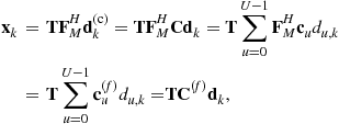 (5.109)
and where the number of orthogonal codes (users) is ![]() .
.
The transmission mode with ![]() is typically called multicarrier CDMA (MC-CDMA) [95,251], whose implementation principle is shown in Figure 5.15.
is typically called multicarrier CDMA (MC-CDMA) [95,251], whose implementation principle is shown in Figure 5.15.

Note that the last line in (5.109) highlights that MC-CDMA corresponds to a CP-CDMA system, which transmits the inverse spectra ![]() of the original codes
of the original codes ![]() , plus a CP to handle IBI and to guarantee easy frequency-domain equalization. This way, MC-CDMA grants both easy PSE and multipath diversity exploitation, since each data symbol is transmitted (spread) by the code matrix
, plus a CP to handle IBI and to guarantee easy frequency-domain equalization. This way, MC-CDMA grants both easy PSE and multipath diversity exploitation, since each data symbol is transmitted (spread) by the code matrix ![]() on several (potentially all) subcarriers. Indeed, the frequency-domain spreading operation expressed in (5.109) is performed on all the
on several (potentially all) subcarriers. Indeed, the frequency-domain spreading operation expressed in (5.109) is performed on all the ![]() subcarriers, and therefore tries to achieve a diversity gain of
subcarriers, and therefore tries to achieve a diversity gain of ![]() . However, the frequency-domain channel coefficients on the
. However, the frequency-domain channel coefficients on the ![]() subcarriers are correlated, because they are obtained by DFT of
subcarriers are correlated, because they are obtained by DFT of ![]() nonzero time-domain channel coefficients in (5.63), with
nonzero time-domain channel coefficients in (5.63), with ![]() . Therefore, the maximum achievable diversity gain is only
. Therefore, the maximum achievable diversity gain is only ![]() . For this reason, similarly to GLP in (5.103), multicarrier CDMA systems can employ an alternative frequency-domain spreading operation that uses only
. For this reason, similarly to GLP in (5.103), multicarrier CDMA systems can employ an alternative frequency-domain spreading operation that uses only ![]() subcarriers out of
subcarriers out of ![]() . In order to minimize the correlation, the
. In order to minimize the correlation, the ![]() subcarriers are chosen as maximally separated, i.e., equispaced. Therefore, using spreading sequences of length
subcarriers are chosen as maximally separated, i.e., equispaced. Therefore, using spreading sequences of length ![]() , we can accommodate up to
, we can accommodate up to ![]() users into the
users into the ![]() subcarriers. If we assume that
subcarriers. If we assume that ![]() is integer, there are
is integer, there are ![]() different groups of equispaced subcarriers, and therefore
different groups of equispaced subcarriers, and therefore ![]() groups of
groups of ![]() users can be accommodated. This scheme is usually known as group-orthogonal MC-CDMA [42], because each group behaves as a reduced-dimension MC-CDMA systems, while the different groups are orthogonal in the frequency-domain, similarly to OFDMA.
users can be accommodated. This scheme is usually known as group-orthogonal MC-CDMA [42], because each group behaves as a reduced-dimension MC-CDMA systems, while the different groups are orthogonal in the frequency-domain, similarly to OFDMA.
The above mentioned group approach is also suitable for multirate transmissions. For instance, the ![]() subcarriers of a given group, and all the
subcarriers of a given group, and all the ![]() associated spreading codes, can be assigned to the same user. In this case, only
associated spreading codes, can be assigned to the same user. In this case, only ![]() users can be accommodated, but the data rate of each user can be
users can be accommodated, but the data rate of each user can be ![]() times higher than conventional MC-CDMA. This multirate scheme is basically a combination of linear precoding and OFDMA, since users, which are orthogonal in the frequency-domain, can apply a linear precoder onto the
times higher than conventional MC-CDMA. This multirate scheme is basically a combination of linear precoding and OFDMA, since users, which are orthogonal in the frequency-domain, can apply a linear precoder onto the ![]() assigned subcarriers, as detailed in Section 2.05.7. Alternatively, multirate transmissions may be obtained by multicode MC-CDMA, as detailed in [187].
assigned subcarriers, as detailed in Section 2.05.7. Alternatively, multirate transmissions may be obtained by multicode MC-CDMA, as detailed in [187].
Another possibility to mix CDMA with OFDM is to apply the CDMA spreading principle to each of the ![]() independent SC transmissions embedded in OFDM, as shown in Figure 5.16. Indeed, by (5.105), each SC data flow can accommodate
independent SC transmissions embedded in OFDM, as shown in Figure 5.16. Indeed, by (5.105), each SC data flow can accommodate ![]() different users by expressing
different users by expressing
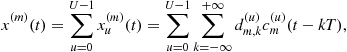 (5.110)
where, ignoring the potential presence of time guards to prevent IBI, the pulse shaper ![]() associated to each data is spread by the chip sequence
associated to each data is spread by the chip sequence ![]() through the signal
through the signal ![]() , as expressed by
, as expressed by
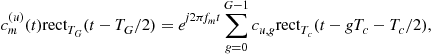 (5.111)
where the code duration is ![]() . The time spreading of each waveform in (5.111) induces a spectrum
. The time spreading of each waveform in (5.111) induces a spectrum
 (5.112)
and an overall spectrum support on the ![]() th subcarrier expressed by
th subcarrier expressed by
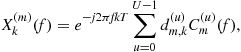 (5.113)
which is centered on ![]() and has equispaced zeros on the frequency grid
and has equispaced zeros on the frequency grid ![]() .
.
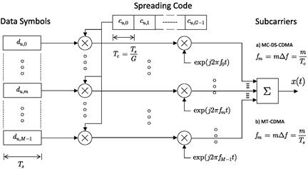
Thus, similarly to classical OFDM, the spectra on different subcarriers will preserve orthogonality if the subcarriers are chosen such that the subcarrier separations are multiple of ![]() , e.g., when
, e.g., when ![]() . This transmission mode is typically called multicarrier direct-sequence CDMA (MC-DS-CDMA) [95]: this corresponds to an OFDM system that transmits a chip of duration
. This transmission mode is typically called multicarrier direct-sequence CDMA (MC-DS-CDMA) [95]: this corresponds to an OFDM system that transmits a chip of duration ![]() in each OFDM block, i.e., in MC-DS-CDMA the OFDM block duration is
in each OFDM block, i.e., in MC-DS-CDMA the OFDM block duration is ![]() , and the symbol duration is
, and the symbol duration is ![]() (see Figure 5.16). Thus, assuming a fixed number
(see Figure 5.16). Thus, assuming a fixed number ![]() of subcarriers, if we want to compare MC-DS-CDMA (with block duration
of subcarriers, if we want to compare MC-DS-CDMA (with block duration ![]() with respect to single-user OFDM (with block duration
with respect to single-user OFDM (with block duration ![]() , two cases are of interest. First, if each MC-DS-CDMA user wants to preserve the same data rate with respect to single-user OFDM systems, the spreading operation imposes a shorter OFDM block duration
, two cases are of interest. First, if each MC-DS-CDMA user wants to preserve the same data rate with respect to single-user OFDM systems, the spreading operation imposes a shorter OFDM block duration ![]() , and, consequently, a bandwidth overexpansion of a factor
, and, consequently, a bandwidth overexpansion of a factor ![]() . Alternatively, if each MC-DS-CDMA user wants to preserve the same bandwidth with respect to single-user OFDM systems, the spreading operation leads to a data rate reduction of a factor
. Alternatively, if each MC-DS-CDMA user wants to preserve the same bandwidth with respect to single-user OFDM systems, the spreading operation leads to a data rate reduction of a factor ![]() , which is a direct consequence of the OFDM block duration
, which is a direct consequence of the OFDM block duration ![]() and of the increased symbol duration
and of the increased symbol duration ![]() . However, it should be emphasized that CDMA systems allows for a maximum of
. However, it should be emphasized that CDMA systems allows for a maximum of ![]() orthogonal users: therefore, in the second case, the aggregate data rate of the
orthogonal users: therefore, in the second case, the aggregate data rate of the ![]() MC-DS-CDMA users would be equal to that of single-user OFDM systems.
MC-DS-CDMA users would be equal to that of single-user OFDM systems.
Moreover, in MC-DS-CDMA, in order to prevent IBI (i.e., inter-chip interference) and grant easy equalization in LTI channels, CP or ZP has to be inserted between each OFDM block (i.e., between each chip). In a vector-matrix notation, this corresponds to a coded (row) vector for each subcarrier expressed by
![]() (5.114)
(5.114)
which leads to an overall spread data-matrix for each user
![]() (5.115)
(5.115)
whose columns are sequentially transmitted by OFDM. In (5.115), ![]() stands for the Kronecker product. The vector transmitted during each chip period is expressed by
stands for the Kronecker product. The vector transmitted during each chip period is expressed by
![]() (5.116)
(5.116)
and the overall transmitted OFDM chip, i.e., OFDM block, is
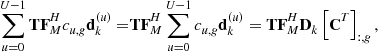 (5.117)
where ![]() is the column-wise data matrix containing the data vector associated to each user, and
is the column-wise data matrix containing the data vector associated to each user, and ![]() is the column vector containing the
is the column vector containing the ![]() th chips of all the users, i.e., the
th chips of all the users, i.e., the ![]() th row of the code matrix
th row of the code matrix ![]() . Equation (5.117) highlights that MC-DS-CDMA grants the easy separation (and equalization) of the
. Equation (5.117) highlights that MC-DS-CDMA grants the easy separation (and equalization) of the ![]() th flow on the
th flow on the ![]() subcarriers by preserving the subcarrier orthogonality through a frequency-selective channel, and the separation among different users by orthogonal design of the code matrix, which requests to collect all the
subcarriers by preserving the subcarrier orthogonality through a frequency-selective channel, and the separation among different users by orthogonal design of the code matrix, which requests to collect all the ![]() chips associated with a single data matrix
chips associated with a single data matrix ![]() .
.
Alternatively, as also shown in Figure 5.16, it is possible to renounce to easy equalization and separation of subcarriers by resorting to the so-called multi-tone CDMA (MT-CDMA) [95]. This system corresponds to choose subcarriers that are not orthogonal on the chip duration, and which would be orthogonal (in the absence of spreading) on the symbol duration ![]() , that is,
, that is, ![]() . Thus, the spectra in (5.112), for different
. Thus, the spectra in (5.112), for different ![]() , are not centered on the zeros of the other spectra as shown in Figure 5.17.
, are not centered on the zeros of the other spectra as shown in Figure 5.17.
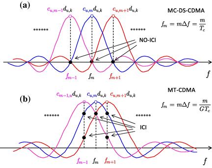
This way, ICI would emerge at the receiver side, independently of the presence or absence of CP or ZP. For this reason, MT-CDMA systems typically avoid the use of a CP [244]. MT-CDMA corresponds to an OFDM system, without CP, on the time interval ![]() , followed by a chip spreading (bandwidth expansion) to distinguish different users [244]. This signal could be generated by a classical OFDM modulator at the symbol rate, followed by
, followed by a chip spreading (bandwidth expansion) to distinguish different users [244]. This signal could be generated by a classical OFDM modulator at the symbol rate, followed by ![]() up-sampling to describe the signal at the chip-rate and by the spreading operation, which is just a chip-by chip multiplication. Due to the fact that a time-domain up-sampling can be easily generated by DFT processing, through a zero-filled spectrum [173], a possible matrix representation for the overall data vector transmitted by the
up-sampling to describe the signal at the chip-rate and by the spreading operation, which is just a chip-by chip multiplication. Due to the fact that a time-domain up-sampling can be easily generated by DFT processing, through a zero-filled spectrum [173], a possible matrix representation for the overall data vector transmitted by the ![]() th user is
th user is
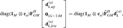 (5.118)
where ![]() is a selection of the DFT matrix
is a selection of the DFT matrix ![]() , containing its first and last
, containing its first and last ![]() rows, and
rows, and ![]() and
and ![]() are two vectors of size
are two vectors of size ![]() obtained by splitting
obtained by splitting ![]() into two parts.
into two parts.
2.05.10.1 Equalization and data recovery for multiuser multicarrier systems
In multicarrier multiuser systems, different data recovery algorithms may be employed, depending on the type of system (e.g., MC-CDMA, MC-DS-CDMA, or MT-CDMA), on the type of communication (e.g., downlink or uplink), and on the type of channel (e.g., linear or nonlinear, time invariant or time varying, with or without multipath, and so on). In this work, as an example, we consider MC-CDMA downlink communications subject to time-invariant multipath channels. We also assume channel knowledge at the receiver side. In this case, after CP removal and FFT processing, by means of (5.65) and (5.108) the frequency-domain received vector can be expressed as
![]() (5.119)
(5.119)
where ![]() represents the
represents the ![]() th received block, with size equal to the number of subcarriers
th received block, with size equal to the number of subcarriers ![]() ,
, ![]() is the frequency-domain channel,
is the frequency-domain channel, ![]() is the code matrix defined after (5.106), with size
is the code matrix defined after (5.106), with size ![]() , where
, where ![]() is the number of users,
is the number of users, ![]() is the transmitted data vector of all the
is the transmitted data vector of all the ![]() users, and
users, and ![]() is the AWGN. Note the similarity of (5.119) with (5.94): indeed, when the number of users is
is the AWGN. Note the similarity of (5.119) with (5.94): indeed, when the number of users is ![]() , MC-CDMA becomes a non-redundant LP-OFDM system with
, MC-CDMA becomes a non-redundant LP-OFDM system with ![]() , and therefore the detection techniques suitable for LP-OFDM can be employed (see Figure 5.14). On the other hand, when
, and therefore the detection techniques suitable for LP-OFDM can be employed (see Figure 5.14). On the other hand, when ![]() , in general the user of interest does not know which codes have been assigned to the other users, and hence the full knowledge of
, in general the user of interest does not know which codes have been assigned to the other users, and hence the full knowledge of ![]() cannot be exploited. Similarly to the suboptimal equalization/detection schemes of ZP-OFDM and LP-OFDM, summarized by (5.90) and (5.99), linear detection schemes can be used also for MC-CDMA, to produce a soft estimate
cannot be exploited. Similarly to the suboptimal equalization/detection schemes of ZP-OFDM and LP-OFDM, summarized by (5.90) and (5.99), linear detection schemes can be used also for MC-CDMA, to produce a soft estimate
![]() (5.120)
(5.120)
and where ![]() is obtained either by (5.91) or (5.92), by substituting
is obtained either by (5.91) or (5.92), by substituting ![]() to
to ![]() .
.
Usually, for MC-CDMA downlink channels, the ![]() th user is interested only to its transmitted data, and consequently performs the data estimation by means of a linear detector that employs only the code
th user is interested only to its transmitted data, and consequently performs the data estimation by means of a linear detector that employs only the code ![]() [95]. In this case, when the
[95]. In this case, when the ![]() th user has no knowledge about the codes of the other users, the joint equalization/despreading in (5.120) can be split in two, as expressed by
th user has no knowledge about the codes of the other users, the joint equalization/despreading in (5.120) can be split in two, as expressed by
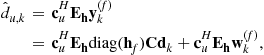 (5.121)
where ![]() is a diagonal matrix that depends on the frequency-domain channel. As clearly expressed by (5.121),
is a diagonal matrix that depends on the frequency-domain channel. As clearly expressed by (5.121), ![]() performs the equalization task, and
performs the equalization task, and ![]() performs the despreading operation.
performs the despreading operation.
For the matrix ![]() , different choices are possible [95]. The choice
, different choices are possible [95]. The choice
![]() (5.122)
(5.122)
known as orthogonal restoring combining (ORC), perfectly compensates for the multipath channel ![]() in (5.119) and restores the orthogonality between users. Therefore, ORC eliminates the inter-user interference, also known as multiple-access interference (MAI). However, the drawback of this ZF approach is a noise enhancement that arises when one or more elements of
in (5.119) and restores the orthogonality between users. Therefore, ORC eliminates the inter-user interference, also known as multiple-access interference (MAI). However, the drawback of this ZF approach is a noise enhancement that arises when one or more elements of ![]() have a low modulus: indeed, in this case, the corresponding elements of
have a low modulus: indeed, in this case, the corresponding elements of ![]() have a high modulus, and hence the noise term
have a high modulus, and hence the noise term ![]() in (5.121) is enhanced. To reduce the noise enhancement, some subcarriers may be excluded from the detection: this ORC variant is known as controlled equalization [95]. An alternative choice for
in (5.121) is enhanced. To reduce the noise enhancement, some subcarriers may be excluded from the detection: this ORC variant is known as controlled equalization [95]. An alternative choice for ![]() is the maximum ratio combining (MRC), as expressed by
is the maximum ratio combining (MRC), as expressed by
![]() (5.123)
(5.123)
By inserting (5.123) into (5.121), it is clear that the MRC approach weights the subcarriers proportionally to their channel amplitudes, and compensate for the different phase offsets of the frequency-domain channel. Therefore, the MRC approach is a sort of frequency-domain matched filter, which maximizes the SNR when there is only a single active user. However, in the presence of multiple users, the amount of MAI may be significant [95]. A third approach, known as equal-gain combining (EGC), tries to avoid both excessive MAI and significant noise boosting, by means of
![]() (5.124)
(5.124)
where ![]() is the vector that contains the phases of the elements of
is the vector that contains the phases of the elements of ![]() . In general, when there are many active users, EGC provides better performance than ORC and MRC [95]. Another possible approach is the MMSE combining (MMSEC), which also tries to balance residual MAI and noise at the detector output. For MMSEC, the matrix
. In general, when there are many active users, EGC provides better performance than ORC and MRC [95]. Another possible approach is the MMSE combining (MMSEC), which also tries to balance residual MAI and noise at the detector output. For MMSEC, the matrix ![]() in (5.121) is expressed by [95,117]
in (5.121) is expressed by [95,117]
![]() (5.125)
(5.125)
Note that the MMSEC expression (5.125) requires also the knowledge of the number of active users ![]() and AWGN power
and AWGN power ![]() . Specifically, at high SNR,
. Specifically, at high SNR, ![]() in (5.125) becomes negligible and therefore MMSEC tends to ORC (5.122), thereby minimizing the MAI at the detector output. From (5.125), it is also clear that noise enhancement is avoided, because, when some elements of
in (5.125) becomes negligible and therefore MMSEC tends to ORC (5.122), thereby minimizing the MAI at the detector output. From (5.125), it is also clear that noise enhancement is avoided, because, when some elements of ![]() have a low modulus,
have a low modulus, ![]() does not contain elements with high modulus. For these reasons, usually the MMSEC detector outperforms ORC, MRC, and also EGC [95].
does not contain elements with high modulus. For these reasons, usually the MMSEC detector outperforms ORC, MRC, and also EGC [95].
If the spreading codes of the other users are known to the user of interest, many other detection strategies are possible [95], including those used for LP-OFDM. For instance, (soft or hard) interference cancellation approaches, or quasi-ML detection techniques, may be pursued. However, we remind that the knowledge of the spreading codes of all users is more reasonable in uplink rather than in downlink. Indeed, in uplink communications, the base station has to detect the signals of all users, and therefore may perform a joint detection of the multiuser signals.
For MC-DS-CDMA, the detection strategies are usually different than for MC-CDMA. Specifically, in time-invariant frequency-selective channels, because of the time-domain spreading of MC-DS-CDMA, the use of orthogonal codes preserves user orthogonality. Hence, the despreading operation is performed in the time-domain, as in DS-CDMA [191] whereas the channel compensation is performed in the frequency-domain, as in OFDM. However, because of the absence of frequency-domain spreading, pure MC-DS-CDMA does not collect frequency diversity, and therefore presents a performance loss with respect to MC-CDMA (see Figure 5.18). To avoid this performance loss, MC-DS-CDMA must incorporate additional features, such as in [127,225], and [259]. On the other hand, MT-CDMA suffers from ICI, and therefore also presents a performance loss with respect to MC-CDMA, especially when the number of users is high (see [95]).