Creative Suite 4 documents have two groups of items: objects, which are editable and which include paths, shapes, type, and even multimedia elements, and images, which are pictures composed of an array of colored pixels. Although you have some crossover, you generally use Photoshop to work with images and Illustrator to work with objects. Most designs combine both of these items. Although all Creative Suite 4 applications use both objects and images and have similar tools, this chapter focuses mainly on Illustrator objects. Images in Photoshop are covered in the next chapter. The other CS4 applications of InDesign, Dreamweaver, Fireworks, and Acrobat have some of the same features for working with objects and images that are found in these two applications.
Several topics apply equally to both objects and images such as color, gradients, and transparency. Although these topics are covered in this chapter on objects, they apply equally to images covered in the next chapter.
This chapter covers lots of ground, including creating objects, the tools used to select them, and a sampling of the features used to edit them. The tools used to edit objects are as diverse as the tools and commands used to create and select them.
The most common Illustrator objects are created using the various drawing tools. These tools are the second section of tools located in the Toolbox directly under the Selection tools, as shown in Figure 9.1. They consist of the Pen tool, the Type tool, the Line Segment tool, the Rectangle tool, the Paintbrush tool, and the Pencil tool. Each of these tools also has several additional flyout tools that you can use to create objects.
Note
The Illustrator Tools palette can toggle between a single vertical column and a double vertical column if you click the arrow icons in the upper-left corner. Photoshop and InDesign also can toggle to a single horizontal orientation.

Drawing in the workspace with any of these tools creates a line that Illustrator calls a path, which is identified as an object. When you select an object, its path and the points that make up its path are highlighted using the layer color. The various selection tools are covered later in this chapter.
In addition to the objects presented in this section, Illustrator includes some other tools that create objects, such as the Symbol Sprayer and Graph tools.
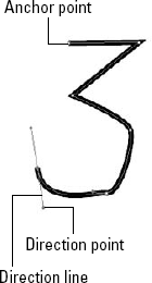
You use the Pen tool to draw several connected lines by simply clicking once where you want the first anchor point and clicking again for each successive connected line.
But the power of the Pen tool isn't in creating straight lines. When you click with the Pen tool to place an anchor point, you can drag to extend a direction line that lies tangent to the curve. At the end of each direction line are direction points that may be moved to alter the curvature at the point. Figure 9.2 shows a path created with the Pen tool.
Tip
If you hold down the Shift key while dragging to create a direction line, the direction line is constrained to 45-degree increments.
You also can use the Pen tool to do the following:
End a path: Hold down the

Tip
The Pen tool provides feedback when creating a new path, adding and deleting points, and closing a path using a small icon beneath and to the right of the tool's cursor.
Create a closed object: Here, the first and last anchor points are the same. Position the last anchor point over the top of the first anchor point until a small circle appears as part of the cursor, and then click.
Add, delete, and convert anchor points on a line: You can perform these tasks by using the Add or Delete Anchor Point tools, which are Pen tool flyout tools. Another flyout tool, the Convert Anchor Point tool, changes points without any direction lines to a smooth curve point. You simply click the point and drag out a direction line. This tool also changes smooth anchor points to corner points without a direction line when you click the anchor points. Holding down the Option/Alt key changes the cursor to the Convert Anchor Point tool.
Add or delete point on a path: With the Pen tool selected, move the cursor over the top of the selected path. A small plus sign appears as part of the cursor when you're over the path; a small minus sign appears as part of the cursor when you're over a point that you may want to delete.
Note
The Pen, Add Anchor Point, Delete Anchor Point, and Convert Anchor Point tools are found in Illustrator, Photoshop, InDesign, Fireworks, and Flash.
Points created with the Pen tool can be selected with the Direct Selection or Lasso tools. If the point includes a direction line, the direction line and its points appear. When a direction line and its points are visible, you can drag them to alter the curvature around the point.
STEPS: Drawing with the Pen Tool
Create a new Illustrator document. Choose File

Enable a snapping grid. Choose View
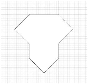
Draw straight lines. Click the Pen tool, and click several times to create an anchor point every time you click.
Close the shape. To close the shape, move the cursor until it's on top of the first anchor point and click. A small circle appears as part of the cursor when it's over the first anchor point. Figure 9.3 shows the simple shape made from straight lines using the Pen tool.
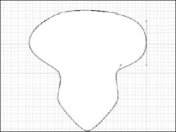
Draw curved segments. With the Pen tool still selected, click to create the same shape beneath the first one, but after clicking each point, drag to pull a direction line out from the point before you release the mouse button. This direction line defines the curvature of the corner. Continue to click around the shape until the shape is closed.
Edit the path points. Select the Direct Selection tool, drag over each anchor point, and compare it to the anchor point across from it. Drag the direction points to make them similar to their opposite corner to make the object symmetrical. Figure 9.4 shows the resulting shapes.
Tip
Illustrator has a preference in the Selection & Anchor Display panel that highlights path points when you move the cursor over them. This helps make points easier to see.
You use the Type tool to create text objects. Clicking with the Type tool creates a Point type object, which you typically you use for a single line of text, such as a heading. You create an Area type object by clicking and dragging in the art board with the Type tool. All text that you type within a text area wraps to fit within the text object area.
Note
Type and all the Type tools are covered in detail in Part IV.
Text objects aren't limited to a rectangular area created by dragging with the Type tool. Using the flyout tools available under the Type tool, you can add text to a selected area or have text follow a path. You also have tools for creating text that runs vertically instead of horizontally.
Note
Type objects you create with the Type tool are a unique type of object. You edit them using the Type tool; you can select them in a similar manner as other objects by dragging over them with the Selection tool.
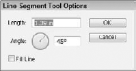
You use the Line Segment tool to create simple straight lines by clicking and dragging on the art board. If you double-click with the Line Segment tool, a dialog box, shown in Figure 9.5, opens where you can specify the line's length and angle. Holding down the Shift key while dragging constrains the line to 45-degree increments; holding down the Option/Alt key while dragging extends the line in both directions from the clicked first point; and holding down the spacebar lets you move the line by dragging.
As flyouts under the Line Segment tool, Illustrator includes tools for creating arcs, spirals, rectangular grids, and polar grids. The Shift key constraints the Line Segment tool to straight horizontal, 45-degree, or vertical lines and the Alt [option] key extends the line outward from the point where you click at both ends.
Tip
If you click the right edge of the tool flyout, you can tear off the flyout to access all the tools simultaneously.
The Rectangle tool creates rectangle objects by dragging in the art board. Clicking without dragging opens a simple dialog box where you can enter precise Width and Height values. Holding down the Shift key creates a perfect square when you drag; holding down the Option/Alt key while dragging creates the rectangle from the center outward; and holding down the spacebar lets you move and position the rectangle as you draw it out.
As flyout tools under the Rectangle tool, you can find the Rounded Rectangle, Ellipse, and Polygon tools. Dragging the Ellipse tool with the Shift key held down creates a perfect circle. Clicking with the Polygon tool opens a dialog box where you can specify a radius and the number of sides to include in the polygon. Illustrator also includes tools for creating pointed stars and flares as flyouts under the Rectangle tool. The Shift key constraints the Rectangle tool to perfect squares and the Alt [option] key creates a rectangle from the center outward where the center is the point where you first clicked.
You can use both the Paintbrush and Pencil tools to draw freehand curves. The difference is that the Paintbrush tool applies art along a path. To draw with either the Paintbrush or Pencil tools, click and drag in the art board.
If you press the Option/Alt key and hold it down after starting a path, a small circle appears as part of the cursor, indicating that you're creating a closed path. When you release the mouse, regardless of where it's located, a line is drawn back to the first anchor point, creating a closed object.
If you double-click either tool in the Toolbox, a dialog box of preferences for the selected tool appears, such as the Paintbrush Tool Preferences dialog box, shown in Figure 9.6. In this dialog box, you can set Fidelity and Smoothness values as well as other options.

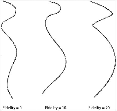
Fidelity: The Fidelity value determines how far the cursor can stray before a new anchor point is created. Increasing this value causes small changes in the path to be ignored. Figure 9.7 shows three curves drawn with the Paintbrush tool with different Fidelity settings. Notice how the curve with the lowest Fidelity value has the most anchor points.
Smoothness: The Smoothness value ranges from 0 to 100 and sets the smoothness of the resulting path.
Fill New Brush Strokes option: Only available for the Paintbrush tool, this option allows you to apply a fill to the path. If the path isn't closed, an imaginary line is drawn between the first and endpoints of the path, and the interior portion is colored with the fill color.
Keep Selected option: This option causes the path to remain selected after you release the mouse button.
Edit Selected Paths option: This option enables you to redraw portions of the path using the selected tool when the cursor is within the specified number of pixels. With this option, you can move the tool over the top of the selected path. If a small x displays as part of the cursor, a new path is created; if the small x disappears, you can drag over the path and replace that portion of the path with the new dragged path.
The flyout tools under the Pencil tool are the Smooth and Erase tools. You can drag the Smooth tool over the top of a selected path to reduce the number of anchor points and smooth the line. You can use the Erase tool to delete the path section that you drag over. You must select the path to use the Erase tool. Editing with these tools is covered later in the chapter.
Tip
You can temporarily enable the Smooth tool when you have the Paintbrush or Pencil tool selected by holding down the Option/Alt key.
The Blob Brush tool (Shift+B) is a pressure sensitive tool that creates Beziér paths of like colors. This is a departure from standard Illustrator brush technology and when combined with the eraser allows great artistic expression of thin-thick line weights.
The Blob Brush tool lets you easily combine several paths of the same color into the same object. Figure 9.8 shows the branches of a tree that have been combined using the Blob Brush. The normal brush would keep each stroke as a separate path. Although the paths are combined, they remain independent from the trunk paths, which are a different color.
The Blob Brush Tool Options dialog box, shown in Figure 9.9, let you define the brush size and shape. You also can control the fidelity and smoothness of the overlapping paths. The Keep Selected option retains the selected object, which makes it easier to see how new paths are added to the selected path.
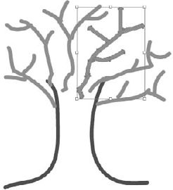
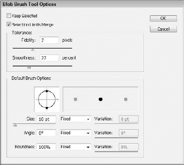
Figure 9.9. The Blob Brush Tool Options dialog box lets you define the characteristics of the Blob Brush tool.
The Path Erase tool can erase portions of the selected path, but it is a detailed tool and has to be right on the path to work. The Eraser tool is much easier to work with and much more forgiving. It works on any objects whether selected or not.
When the Eraser tool is dragged over an open path it removes any portion of the path that is obscured, so it can quickly clean up any leftover path pieces. When the Eraser tool is used on a closed path, the tool changes the path as if the pixels underneath the tool were removed. Figure 9.10 shows an example of some closed paths that were altered with the Eraser tool. This provides a simple way to cut holes within a closed shape.
Double-clicking the Eraser tool opens the Eraser Tool Options dialog box where you can alter the tool's angle, roundness, and diameter. Additional options make each of these attributes fixed or random with a designated amount of variation.
InDesign, like Illustrator, relies heavily on the concept of objects. In fact, everything placed in an InDesign document is an object. Objects are created in InDesign using the tools found in the second section of the Toolbox, shown in Figure 9.11, including the Pen tool, the Type tool, the Pencil tool, the Line tool, the Rectangle Frame tool, and the Rectangle tool along with the additional tools available as flyouts.
All these tools include features that are similar to the Illustrator tools, but InDesign includes some additional object types created with the Frame and Shape tools. Frames offer a way to create an image placeholder, and the various shape tools are used to add a variety of shapes. The key difference between frames and shapes in InDesign is the initial state of the stroke and fills. The drawing tools, on the other hand, apply the current stroke and fill.

Note
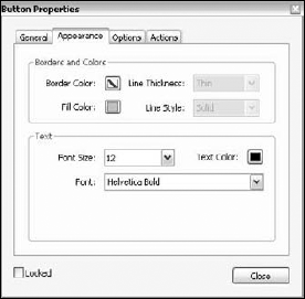
Creating and using interactive buttons in InDesign is covered in Chapter 29.
Although Photoshop's forte is working with images, you also can use Photoshop to create shapes. The tools used to create objects in Photoshop are located in the third section of tools in the Toolbox, as shown in Figure 9.12. They include a Type tool, a Pen tool, and a Rectangle tool, along with several additional tools available as flyouts.
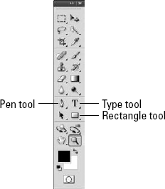
When you select one of these drawing tools, the Options bar, shown in Figure 9.13, displays all the drawing tools. Selecting a drawing tool and clicking the drop-down options to the right of the Custom Shape Tool opens a pop-up menu of settings for the selected tool. These pop-up menus of settings let you enter precise Width and Height values for the shapes.
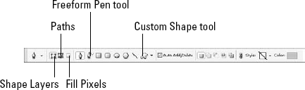
Photoshop also includes a Freeform Pen tool, as a flyout under the Pen tool that acts like Illustrator's Pencil tool. It lets you draw freehand paths. If you enable the Magnetic option in the Options bar, the Freeform Pen tool detects areas of contrast and snaps the line to follow a pixel image behind it.
Tip
If you're having trouble with the Pen tool, try enabling the Rubber Band option, which makes it easier to learn to use the Pen tool.
The Photoshop object tools (referred to in Photoshop as drawing tools) also work just like their Illustrator counterparts. Among these tools is a unique tool called the Custom Shape tool, which is a flyout under the Rectangle tool and which is available in the Options bar at the top of the screen whenever any of the shape tools are active.
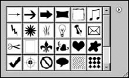
The Custom Shape tool lets you select a custom shape by right-clicking in the workspace after selecting the Custom Shape tool or through the drop-down menu on the Options bar, shown in Figure 9.14. You add the selected shape to the document by dragging with the tool. Add new shapes to the pop-up menu by choosing Edit
Photoshop custom shapes are similar to Illustrator's symbols, except that there are no update or replace features.
Note
Symbols are covered in the "Using Symbols, Graphic Styles, and Swatches", section later in this chapter.
If you select the Paths option in the Options bar, select a drawing tool, and then create a shape, Photoshop adds the shape to the Paths palette, shown in Figure 9.15. You can then use these paths to mask areas or define a clipping path. You also can convert them into a selection.

You also can export paths to Illustrator by choosing File
Note
Using paths as clipping masks is covered in the "Creating a clipping mask in Illustrator" section later in this chapter.
Paths drawn on an image are temporary and appear with the name Work Path in the Paths palette. If you deselect the Work Path in the Paths palette and draw another path, then the new path replaces the first path. Because paths placed in the Paths palette are temporary, you can save them using the Save Path palette menu command. This opens a simple dialog box where you can name the saved path. The saved path then appears permanently in the Paths palette where it can be selected and reused.
All shapes drawn in Photoshop as objects are contained within special layers called shape layers. If a single shape layer includes multiple shapes, you can use the Pathfinder buttons to add, subtract, intersect, or exclude the overlapping areas.
Note
More on the Pathfinder commands is covered in the section "Using Pathfinder features."
If you select the Fill Pixels option in the Options bar when drawing a shape in Photoshop, the shape becomes rasterized and becomes part of the pixel layer. For these painted shapes, you can select a blending mode and an opacity. You also can rasterize existing shapes by choosing Layer
Smart Objects are objects that know the application used to create them and by double-clicking on them or by selecting the Layer
Smart Objects are created in Photoshop using the Open As Smart Object menu command, but they also can be created by placing a file, pasting a file from Illustrator, or converting a Photoshop layer to a Smart Object. Smart Object layers are easy to identify in the Layers palette because they include a special icon in the lower-right corner of the thumbnail.
Tip
One roundabout method for working with Smart Objects in Photoshop is to place a Photoshop image within the current document. This creates a Smart Object layer and lets you work with the image, such as transforming the image, in a nondestructive manner. If the original image needs to be edited, you can simply select the Layer
All items in an Acrobat document are objects. Most of these objects are created from the original document when it's converted into a PDF file, but Acrobat 8 Professional also lets you create several objects that you can use to enhance the Acrobat document or to add review comments.
You select most Acrobat objects by choosing Tools
Objects used to enhance a PDF document—including the Article tool, the Movie tool, the Sound tool, the TouchUp Text and TouchUp Object tools, and several Form object tools—are located in the Tools
Article tool: Use this to add several threaded text areas to the document. To create an article object, drag to create each of the threaded text areas and press the Enter key to complete the article. After the article is completed, a Properties dialog box appears, where you can enter the title, subject, author, and keywords for the article.
Video and Flash tools: Use these to add movie or Flash files to an existing PDF document. After selecting either of these tools and dragging in the document, a dialog box opens where you can browse to the desired movie or sound file.
Note
The details of using movie and sound files within an Acrobat document are covered in Chapter 29.
TouchUp Text tool: Use this to edit an existing piece of text. Selecting the Text TouchUp tool and clicking in the document with the
Form object tools: The Tools
All the commenting objects for reviewing a document are included in the Tools
The Comment & Markup menu also includes the Stamps submenu, which is used to add stamped image objects to the document. The Stamps submenu includes many different default stamps choices, including stamps that say Approved, Confidential, Void, and so on. Also included is a category of dynamic stamps that include the applier's name and date.
To add more attention to a comment, you may select to use one of the tools found in the bottom of the Comment & Markup menu. These tools include a collection of drawing tools, including tools for creating rectangles, ovals, arrows, lines, clouds, polygons, and polygon line objects.
The Comment & Markup menu also includes a Text Edits tool that creates highlighted text area objects, the Pencil tools, which lets you draw freehand objects, and the Pencil Eraser tool, which erases lines drawn with the Pencil tool. In addition, the Attach a File as a Comment menu command opens a dialog box where you can select a file to attach to the document. After you've selected the file, the File Attachment Properties dialog box, shown in Figure 9.17, appears; here, you can define how the attachment looks in the PDF document. The Record Audio Comment tool opens a Sound Recorder, where you can record a simple audio message or select a sound file to attach to the document.

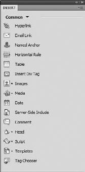
Dreamweaver also uses objects extensively to lay out Web pages. All the objects that you can add to a Web page are available in different tabbed categories in the Insert panel. The various tabbed categories include Common, Layout, Forms, Data, Spry, Text, and Favorites. Selecting a category displays all the available objects as icon buttons. Figure 9.18 shows many of the objects in the Basic Objects category.
An object is added to a Web page by clicking its icon button to make the object's properties dialog box appear. After an object is created, you can access its properties in the Properties palette at the bottom of the interface. You also can add objects while using the Code view.
Unlike objects, which can be thought of as a group of items sitting on a shelf ready for you to place in a document, you create images by drawing them on a canvas or by loading an existing image file. All the CS4 applications also support images, but the first place to look is obviously Photoshop.
Note
The process of creating objects within the CS4 applications is referred to as drawing, and the process of creating images is called painting.
The main tools used in Photoshop to paint images are the Paintbrush tool, the Pencil tool, and the Paint Bucket tool. All these tools apply the foreground color to the canvas.
The Paintbrush tool coupled with the Brushes palette offers unlimited flexibility and power in applying paint to the canvas. Selecting the Brush tool (B) in the Toolbox changes the cursor to match the shape of the selected brush. Dragging with this tool in the canvas paints a line using the properties set in the Brushes palette.
You may open the Brushes palette, shown in Figure 9.19, by choosing Window

Note
The Brushes palette is active only when one of the painting tools is selected.
Brush Presets: This panel lets you choose a brush from a long list of presets. To select a preset brush, just click it and a preview of the selected brush appears at the bottom of the panel. You also can change the Master Diameter for the selected brush. In the Brush palette menu are several options for setting how the preset brushes are viewed, including Text Only, Small and Large Thumbnails, Small and Large Lists, and Stroke Thumbnail.
The Brush palette menu also includes a New Brush Preset option that is used to add a new preset to the Brush Preset panel. A set of brush presets may be saved to the local system using the Save Brushes palette menu command. The brush libraries are saved using an ABR file extension. Photoshop includes several brush libraries that may be loaded into the Brushes palette or selected from the bottom of the Brushes palette menu.
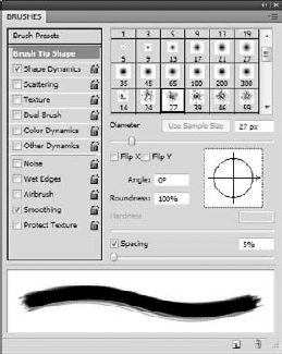
Brush Tip Shape panel: Shown in Figure 9.20, this panel displays thumbnails of the brush tips for the respective brush presets listed in the Brush Presets panel. The brush tip properties let you change the tip's diameter and orientation using controls to flip the brush tip and set its angle and roundness. You also can alter its Angle and Roundness values by dragging in the diagram pane to the right of the Angle and Roundness values. The Hardness value sets the diameter of the brush's hard center, where no softening takes place. The Spacing value determines the distance between successive brush marks in a stroke. Low Spacing values cause the brush tip to overlap into a continuous path.
Shape Dynamics and other panels: This panel includes controls to add some randomness to the brush strokes, including the amount of jitter that is added. The Scattering panel is used to spread the brush tip over a given width with a specified density. The Texture panel lets you specify an underlying texture for the brush. The Dual Brush panel lets you select a secondary brush tip that is combined with the original brush tip to create a new unique pattern. The Color and Other Dynamics panels let you specify how the colors, transparency, and brightness change as the brush is painted.
The Noise, Wet Edges, Airbrush, Smoothing, and Protect Texture options don't open a panel of settings but may be enabled to change the characteristics of the selected brush.
When the Paintbrush tool is selected, the Options bar includes controls that let you select a tool preset or a brush tip. You also can select a blending mode to use and change the amount of opacity and flow that is applied to the brush.
As you paint with the Paintbrush tool, you can dynamically alter the brush size by dragging with the Ctrl and Alt (Option) keys held down. You also can change the brush's hardness value while painting by dragging with the Ctrl, Alt (Option), and Command keys held down.
STEPS: Painting with the Paintbrush Tool
Open a Photoshop document. With Photoshop open, choose File
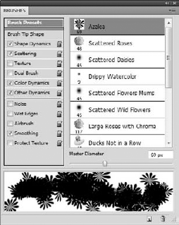
Select a Brush. Click the Paintbrush tool to select it. In the Options bar, click the Brushes tab to open the Brushes palette. Click the palette menu, and select the Special Effect Brushes command. A dialog box opens asking if you want to replace the brush sets. Click OK. The new brush set is displayed in the Brush Presets panel, as shown in Figure 9.21. In the Brush Presets panel of the Brushes palette, select the first brush preset, called the Azalea brush.
Set the brush properties. In the Swatches palette, select an orange color. This color becomes the new foreground color. Click the Color Dynamics panel in the Brushes palette, and drag the Hue Jitter over to 50%.
Paint with a Preset brush. Drag with the Paintbrush tool in the canvas. The Azalea brush paints a random assortment of colored flowers in the canvas, as shown in Figure 9.22.
The Pencil tool works just like the Paintbrush tool, except it produces a hard edge instead of a smooth, soft edge. The Pencil tool uses all the same controls found in the Brushes palette for specifying its shape and characteristics.
The Paint Bucket tool, located as a flyout under the Gradient tool, applies the selected foreground color or pattern to an area where all the contiguous pixels are the same or within the specified Tolerance. You can select the properties of the Paint Bucket tool in the Options bar when the Paint Bucket tool is selected. You also can select a blending mode and an opacity.
All the other CS4 applications can work with images, but these images are confined to an object or frame. This lets you transform the images within the work area and place them relative to the other objects, but Illustrator and InDesign don't include any tools that alter the pixels by painting. You can load images into Illustrator and InDesign using the File
You also can convert certain text and vector objects to their bitmap equivalents through a process called rasterizing. Raster images may be moved back to Photoshop using the Clipboard. When pasted into Photoshop, the images are contained within a frame that allows you to move the object, but when you select a different tool, a confirm dialog box asks if you want to place the object. Choosing to place the object permanently places it in the current image.
Illustrator also includes a Live Trace feature that works the opposite of rasterizing, allowing you to convert images into vectorized objects.
Warning
Rasterizing objects eliminates their resolution independence. Scaling a rasterized object reveals all the individual pixels.
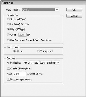
You can rasterize Illustrator objects by choosing Object
Color Model options: Include RGB, CMYK, Grayscale, or Bitmap, depending on the color settings for the document.
Background options: Define whether the object background is colored as white pixels or made transparent. Selecting the Transparent option causes an alpha channel to be saved with the document.
Anti-Aliasing options: Include None, Art Optimized (which is used for graphics), and Type Optimized (which is used for text).
Create Clipping Mask: Creates a clipping mask that hides all the background pixels. It isn't needed if the Transparent Background option is selected.
Add field: Lets you specify a distance that is added to every edge of the rasterized object.
You can define all these settings for the document using the Document Raster Effects Settings dialog box, shown in Figure 9.24, which you open by choosing Effect
Note
More on using effects is covered in Chapter 13.

STEPS: Rasterizing Objects
Create a new Illustrator document. With Illustrator open, choose File
Drag a symbol from the Symbols palette. For a quick object that may be rasterized, drag a symbol from the Symbols palette onto the art board.
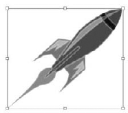
Resize the object. Because the object loses its resolution independence when it's rasterized, drag on the bounding-box handles of the symbol with the Shift key held down to maintain its aspect ratio until it is the size you want to use, as shown in Figure 9.25.
Rasterize the symbol. With the symbol selected, choose Object

Note
If you intend to use the image in Photoshop, then you can paste the object as a smart object. This preserves the vector data and rasterizes the image on the fly when copied to Photoshop.
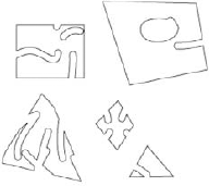
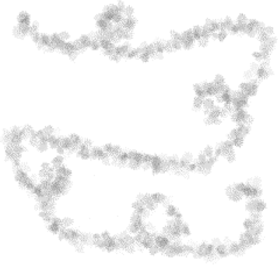
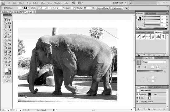
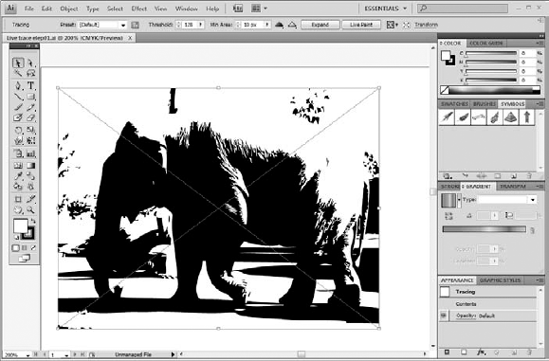
Just as you can rasterize vector objects into pixel images, Illustrator also includes a feature that reverses the process. Illustrator's Live Trace takes raster images and traces them into editable objects. Figure 9.27 shows a simple sailboat image that has been traced into black and white objects.
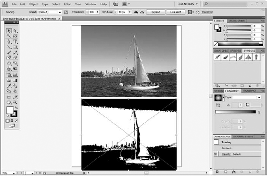
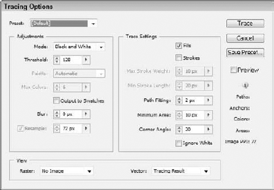
The Live Trace button appears in the Options bar anytime a raster graphic is selected in Illustrator. After a raster graphic is traced, the Options bar displays a drop-down list of Presets that you can select. The Options bar also includes a button to open the Tracing Options dialog box, shown in Figure 9.28. After tracing the image, the Options bar also includes a setting for controlling the Threshold and the Minimum Area. The Threshold value applies to the black and white tracing mode. All pixels in the trace area lighter than the Threshold value are converted to white, and all pixels darker are converted to black. The Minimum Area setting controls the size of the details considered during the trace pass. Details in pixel areas smaller than the Minimum Area value are ignored.
Live Trace also can be selected from the Object
Note
The Live Trace options can be changed as long as the trace is not expanded or converted to a Live Paint object. A linked image can also be manipulated in Photoshop to alter the tone or contrast in order to influence the Live Trace outcome.
You can remove the existing tracing using the Object
STEPS: Using Live Trace
Open an Illustrator document. With Illustrator open, choose File
Select the bitmap image. Choose the Selection tool, and click the raster image in the center of the artboard.
Use Live Trace. With the image selected, select the Object
Open the Tracing Options dialog box. Select the Object
Expand the traced image. With the traced image still selected, choose the Object

Before the properties of an object are displayed, you need to select the object that you want to change. Selecting an object is as easy as clicking it with the Selection tool. When selected, the object is surrounding with a bounding box. An object's bounding box may be used to transform the object.
Note
Dreamweaver is the anomaly when it comes to selection. Because Dreamweaver doesn't have any selection tools, objects are selected in Design view by clicking them with the cursor.
Note
Transforming objects is covered in Chapter 12.
The core Selection tools—including the Selection and Direct Selection tools found in Illustrator, Photoshop, InDesign, Fireworks, and Flash—all work the same.
Note
Acrobat is also a little different in how it selects objects.
Both the Illustrator and InDesign Toolboxes include several tools for selecting objects and parts of objects. These tools are located at the top of the Toolbox, as shown in Figure 9.32 for Illustrator include the Selection tool, Direct Selection tool, the Magic Wand tool, and the Lasso tool. InDesign includes the Selection and Direct Selection tools.
Note
Illustrator and InDesign have a Group Selection tool that is used to select individual objects within a group and groups of objects.

Selection tool: The simplest way to select objects is to click them with the Selection tool. You also can select multiple objects by dragging over them with the Selection tool (V). All objects that are at least partially included within the area that is dragged over are selected. You also may select multiple objects by holding down the Shift key while clicking each object.
Tip
You can access the most recently used selection tool in Illustrator regardless of the current tool by holding down the
Direct Selection tool: Use this to select individual points or segments on a path. When a path point is selected, it appears solid; unselected path points appear hollow. When the Direct Selection tool (A) is over the top of a line segment, a small line appears as part of the cursor; if the Direct Selection tool is over an anchor point, a small hollow square appears as part of the cursor and the selected anchor point appears larger to make it easier to select.
Note
If only a single path point is selected with the Direct Selection tool and the Scale tool is selected, then the scale only affects the direction handles on the selected point.
Illustrator's Group Selection tool (available as a flyout under the Direct Selection tool) may be used to select a single object that is part of a group. Clicking a grouped set of objects selects the object and the group it belongs to. Each successive click adds another group level.
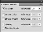
Illustrator's Magic Wand tool (Y) is used to select all objects that have a similar fill color or pattern, but using the Magic Wand palette, shown in Figure 9.33, you can choose to have the Magic Wand tool select all objects with a similar fill color, stroke color, stroke weight, opacity, and blending mode. For each of these (except for blending mode), you can specify a Tolerance value. The Tolerance value determines how loose the selected attribute may be while still being selected.
Illustrator's Lasso tool (Q) also may be used to select multiple path points on multiple objects. Every object that has a point encircled by the Lasso tool is selected. Holding down the Shift key lets you add to the current selection; holding down the Option/Alt key subtracts from the current selection.
Note
You cannot select objects that are locked or hidden. To unlock all objects, choose Object
Although you use most of Photoshop's selection tools to make pixel selections, Photoshop also includes Selection and Direct Selection tools specifically for selecting objects. When you select a layer containing images in the Layers palette, you can use Photoshop's Marquee, Lasso, Magic Wand, or Quick Selection tools to select a pixel area. You move pixel selections using the Move tool, but the Move tool also is used to move objects when an object is selected.
When objects are created in Photoshop, each object resides on its own layer. Photoshop CS4 lets you select multiple layers by holding down the Shift key. Once multiple layers are selected, they can be moved and altered as needed.
You can use the Layers palette to select all objects contained on a layer or individual objects within that layer. To the right of the layer name in the Layers palette is a circle button used to target objects. Clicking this target button for a given layer selects all objects on that layer. If you expand a layer, you can select the individual objects that make up the layer.
Note
Layers are covered in detail in Chapter 25.
In addition to the Toolbox tools, there are many selection-menu commands available in the Select menu. Choose Select
Note
Photoshop also includes a Select menu, but all these menu commands apply to the pixel selection tools, which are covered in Chapter 11.
Choosing Select
Objects also can be selected using their stacking order. Choosing Select
Note
The First Object Above, Next Object Above, Next Object Below, and Last Object Below menu commands are found in InDesign's Object
The Select
The Select
The Select
Note
The Save Selection feature in Photoshop lets you save a selection as a mask in an alpha channel. These saved selections are stored in the Channels palette. When saving the selection to a channel, you can choose to combine the selection with other defined channels using the Replace, Add to, Subtract from, or Intersect with commands.
Just as Illustrator and InDesign include several tools that select objects, Photoshop includes several tools that select specific pixels. The Selection tools are located at the top of Photoshop's Toolbox and include several Marquee tools, several Lasso tools, and the Quick Selection tool, as shown in Figure 9.34.

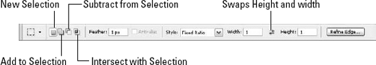
When one of the Selection tools is selected, the Options bar displays four icon buttons that are used to create a new selection, add to the current selection, subtract from the current selection, and intersect with the current selection. These buttons let you continuously edit a selection until you have exactly what you want.
Holding down the Shift key while selecting an area adds to the current selection. Holding down the Option/Alt key subtracts from the current selection. Holding down the Shift+Option/Alt keys intersects the current selection.
The Options bar also lets you specify a feather amount and includes an option to enable anti-aliasing. Dragging with a selection tool in the canvas marks a selection with a blinking dashed line often called marching ants.
Note
If a selection isn't visible, choose View
You can display only one selection on the canvas at a time, but you may save and load selections by choosing Select
The Marquee selection tools (M) included in Photoshop include the Rectangle Marquee tool, the Ellipse Marquee tool, the Single Row Marquee tool, and the Single Column Marquee tool. The difference among these tools is the shape of the selection they make.
In the Options bar, which appears directly under the menu at the top of the interface, shown in Figure 9.35, you can choose a selection Style as Normal, Fixed Aspect Ratio, and Fixed Size. If the Normal option is chosen, then a selection is made by clicking and dragging to specify the selection size. The Fixed Aspect Ratio option lets you specify Width and Height values. Dragging with this option produces a selection that maintains the specified aspect ratio. The Fixed Size option also lets you specify Width and Height values. Clicking and dragging with this option drags a selection of the specified dimensions in the image.
Holding down the Shift key while dragging with the Rectangle or Ellipse tools constrains the selection to a perfect square or circle. You also can hold down the Option/Alt key to drag from the center of the shape. Holding down the spacebar lets you move the current selection as you make it. When you release the spacebar, you can continue dragging to create the selection. The Single Row and Single Column Marquee tools let you click to select a single row or column of pixels.
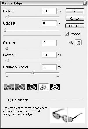
At the right end of the Options bar is the Refine Edge button. Clicking this button opens the Refine Edge dialog box, shown in Figure 9.36. This dialog box lets you make adjustments to the selection using a set of simple sliders. The sliders let you change the Radius and Contrast of the selection edge and also the smoothness and feather amount. The Contract/Expand slider changes the size of the selection.
Photoshop actually includes three different Lasso tools (L):
Lasso tool: You create a selection by drawing in the canvas. When you release the mouse, a straight line is drawn back to the point where you first clicked. If you hold down the Option/Alt key, you can click and drag to create straight lines. With the Option/Alt key held down, you also can press the Delete key to delete the last created straight line point or gradually delete the drawn path.
Polygonal Lasso tool: This is the opposite of the Lasso tool. You create a selection by clicking at the endpoints of each successive straight line, but if you hold down the Option/Alt key, you can draw freehand. The Delete key also works to delete line segments. To close a selection created with the Polygonal Lasso tool, move the cursor near the starting point until a small circle appears as part of the cursor, and click or hold down the
Magnetic Lasso tool: This automatically creates selection anchor points based on the contrast of the image below. To use this tool, set the Width, Edge Contrast, and Frequency values in the Options bar. The Width value specifies how far around the cursor the Magnetic Lasso tool looks for contrasting pixels. The Edge Contrast value sets the amount of contrast required for an edge to be selected. The Frequency value determines the number of anchor points used to define the selection area.
Click an image border that you want to trace with the Magnetic Lasso tool and drag along the image border. The tool places anchor points regularly along the path and connects them. If you click, you can manually place an anchor point as needed. The Delete key may be used to backtrack if needed, and holding down the Option/Alt key changes the Magnetic Lasso tool to the normal Lasso tool for dragging or the Polygonal Lasso tool for clicking. Double-click or drag back to the first point again to close the selection.
The Quick Selection tool (W) lets you select like-colored sections using a brush. The Options bar offers controls for changing the brush's size and edge refinement. You also can add or subtract from the current selection. As you paint over the image, the Quick Selection tool automatically selects all the like-colored pixels within the section where you paint.
The Magic Wand tool is located as a flyout under the Quick Selection tool. It selects all areas with the same color or a color that is within the specified Tolerance value. The Tolerance value (found on the Options bar) can range between 0 and 255. Tolerance values of 0 require that the color values be exactly the same, and a Tolerance value of 255 is so forgiving that almost all colors are selected.
On the Options bar, the Contiguous option selects only those areas immediately connected to the selected color, but if the Contiguous option is deselected, all colors within the canvas that are within the Tolerance value are selected. The Use All Layers option makes selections from all layers but only from the selected layer if disabled.
STEPS: Building a Selection
Open a Photoshop document. With Photoshop open, choose File
Choose an initial selection. Click the Rectangle Marquee tool, and drag in the canvas to select a rectangular area.
Subtract an interior section. With the Rectangle Marquee tool still selected, click the Subtract from Selection button in the Options bar. Then drag over an interior section of the current selection. The interior section is removed from the selection.
Use the Ellipse Marquee tool. Click and hold the Rectangle Marquee tool to select the Ellipse Marquee tool from the flyout menu. Click the Add to Selection button in the Options bar. Then select the Fixed Size Style with Width and Height values of 64 pixels. Click and drag the circular selection so it's positioned on top of each of the corners of the current selection.
Save the selection. With the selection completed, choose Select
Fill the selection. Choose Edit

In addition to the Selection tools, Photoshop also includes a Select menu that holds many commands that are helpful for selecting pixels. Choose Select
Choosing Select
Note
If a selection exists in the canvas, opening Photoshop's Color Range dialog box displays the selected area only. If no selection exists, the entire image displays in the Color Range dialog box.
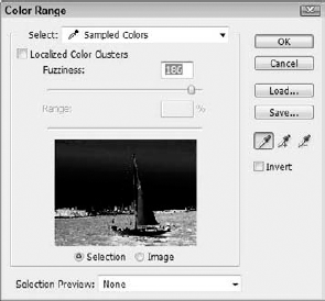
The Localized Color Clusters option causes areas similar in color to be taken into account. This provides a good way to separate foreground pixels from background colors like the sky. Increasing the Fuzziness value increases the color range included in the selection, much like the Tolerance value for the Magic Wand.
To add more colors to the selection, click the Add to Sample eyedropper; to remove colors, click the Subtract from Sample eyedropper. You also can select the Add to Sample eyedropper by holding down the Shift key and the Subtract from Sample eyedropper by holding down the Option/Alt key. The Invert option switches the colors used in the Preview pane.
The Select drop-down list at the top of the dialog box lets you select from several default colors, including reds, yellows, greens, cyans, blues, magentas, highlights, midtones, shadows, and out of gamut. The Out of Gamut selection in particular is useful as a color check prior to printing.
The Selection Preview options at the bottom of the dialog box project the selection back into the canvas using None, Grayscale, Black Matte, White Matte, or Quick Mask. Color Range selections may be saved using the AXT file extension and reloaded again.
The Select

Choosing Select
Paths that are saved in the Paths palette may be turned into a selection using the Make Selection palette menu command. This opens the Make Selection dialog box where you can select a Feather Radius value and whether the selection is anti-aliased. You also can choose that the selection is a New Selection, added to the existing selection, subtracted from the existing selection, or intersected with the existing selection.
Tip
You also can Ctrl/
Illustrator and InDesign both include several ways to organize objects. Chief among these is the Layers palette, which lets you place objects on separate layers. Other organization features are contained within the Object menu; these features help in grouping and preventing unwanted edits by locking and hiding objects.
Note
The Object menu includes many other commands, such as commands to transform and arrange objects. These commands are covered in Chapter 12.
All of the print-oriented CS4 applications have layers accessed through a Layers palette. You create new layers by selecting the New Layer palette menu command or by clicking the New Layer icon button at the bottom of the palette. All new objects are added to the selected layer, and objects may be moved between layers.
Note
Although Acrobat doesn't have a Layers palette, layers can exist in a PDF file created using one of the other CS4 applications and be viewed in Acrobat using the Layers interface.
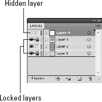
The first two columns of the Layers palette in Illustrator and InDesign let you hide or lock layers by clicking in the column boxes. Locked and hidden layers cannot be selected or edited.
Note
Turn to Chapter 25 for much more information on layers.
You may group together several selected objects by choosing Object
Tip
It is often easier to select individual members of a group with the Direct Selection tool than with the Group Selection tool.
To prevent set objects from accidentally being selected or edited, you can lock and hide objects in Illustrator by choosing Object
Objects or layers that are locked have a small lock icon displayed in the second column of the Layers palette, as shown in Figure 9.40, and objects or layers that are hidden have no eye icon in the first column of the Layers palette. The Layers palette provides another way to quickly hide and lock objects by clicking the palette's columns.
Note
You also can lock or hide layers in Photoshop using the Layers palette. Select the layer, and click the Lock Position or Lock All icons at the top of the Layers palette. When locked, a small lock icon appears to the right of the Layer name. You hide layers in Photoshop clicking the eye icon in the first column of the Layers palette.
The two properties probably most common for objects are the object's fill and stroke. An object's fill is the color, gradient, or pattern that fills the interior portion of an object, and an object's stroke is the line or outline that makes up the object. Fills and strokes may be any color, or they may be set to no color. Fills also may be added with a gradient or a pattern.
Note
Applying fill and stroke colors in Flash works differently than the other CS4 apps.
Note
InDesign can apply a gradient to a stroke, but the other applications cannot.
Fill and stroke colors are applied to objects using the colors for each that are identified in the Fill and Stroke boxes located at the bottom of the Toolbox, as shown in Figure 9.41. The Fill box looks like a filled colored square; the Stroke box looks like a thick outlined square. The Fill box is active by default, but you can click the Stroke box to select it.
With either the Fill or Stroke box in the Toolbox active, you can change the box's color by selecting a new color from the Color or Swatches palette, or you can double-click the box to access a Color Picker dialog box.
The double-headed arrow that appears above and to the right of the Fill and Stroke boxes swaps the colors, so the Fill color becomes the Stroke color and vice versa. The small icon to the lower left of the Fill and Stroke boxes set the Fill and Stroke colors to their defaults, which are a white fill and a black stroke in Illustrator and Photoshop and no fill and a black stroke for InDesign.
Tip
The keyboard shortcut to swap the Fill and Stroke colors is Shift+X; the keyboard shortcut for setting the fill and stroke colors to their defaults is D.
Below the Fill and Stroke boxes in the Toolbox are three simple icons, shown in Figure 9.42. These icons are used to set the active Fill or Stroke box to hold a Color (<), a Gradient (>), or None (/). When the None icon is clicked for either box, a red diagonal line appears in the box.
Warning
Gradients may be applied only to a Fill, not to a Stroke, in Illustrator. If the Gradient button in Illustrator is clicked for a stroke, a gradient is added to the Fill box. InDesign can add gradients to strokes.
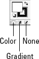
Figure 9.42. The icons under the Fill and Stroke boxes can fill the selected object with a color, a gradient, or neither.
If the fill and stroke colors are changed without any objects selected, the default colors are applied to all new objects created from that point on.
The Color and the Swatches palette also includes Fill and Stroke boxes that match those in the Toolbox, as shown in Figure 9.43.

One other place that may be used to change fill and stroke colors is the Appearance palette. Using the Appearance palette, shown in Figure 9.44, you can change the stacking order for fills and strokes. Attributes listed in the Appearance palette are applied to an object from front to back in the order that they appear in the Appearance palette.

By dragging the fill above the stroke, the fill appears above the stroke, making any portion of the stroke that overlaps the fill hidden behind the fill.
Although the only attribute that may be applied to a fill is a color, gradient, or pattern, strokes include several additional attributes. These attributes are applied using the Stroke palette, shown in Figure 9.45.
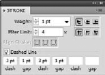
The stroke weight defines how thick the stroke is. By default, half of the weight thickness appears on either side of the object path marked in the object's layer color when the object is selected. Stroke weights ranging from 0.25 points to 100 points may be selected from the pop-up menu to the right of the Weight field, or you may enter a custom weight value in the Weight field.
Note
Entering a Weight value of 0 sets the stroke to None.
Selecting the Show Options palette menu command causes several additional stroke attributes to appear at the bottom of the Stroke palette. These options are also visible when you access the stroke controls in the Options bar.
The row of icons that appears to the right of the Weight field lets you select from three different cap styles that are applied to the end of the stroke. The three options are Butt Cap, Round Cap, and Projecting Cap. Butt Cap squares the ends of a stroke, Round Cap applies half a circle to the stroke ends, and Projecting Cap applies a square end that is extended half a line width beyond the end of the stroke.
Note
Selecting a cap style for a closed object with no dash such as a rectangle has no effect.
Beneath the three cap style buttons are three Join options. These buttons define how the corners of an object appear and has an effect on dashed strokes, making them visible on closed objects. The Join options are Miter Join, Round Join, and Bevel Join. Miter Join draws the corners as sharp squares, Round Join rounds the corners, and Bevel Join replaces the corners with diagonal lines. The Miter Limit sets a limit for the corner point as a number times the weight when Miter Joins are automatically switched to Bevel Joins.
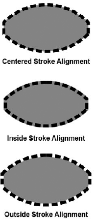
The Align Stroke options let you move a stroke so its thickness is centered on the objects boundary, so the stroke's thickness is inside the object, or so it is outside the object. Setting the Align Stroke option to Outside causes the stroke to be completely free of the fill color, but setting the alignment to Inside causes the stroke to conceal a portion of the fill color. Figure 9.46 shows each of these alignment options.
If the Dashed Line option is selected, you can enter the Dash and Gap values for three separate dashes, enabling you to create many unique dashed lines. Not all the Dash and Gap values need to be filled in. Whatever values are entered are repeated around the entire object.
Figure 9.47 shows several stroke samples of various weights, cap types, and dashed lines.
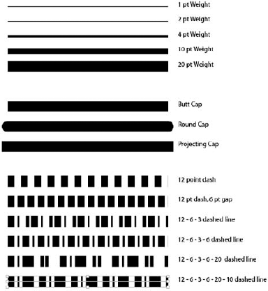
Figure 9.47. Altering the settings in the Stroke palette changes the attributes for the stroked path.
STEPS: Applying Fills and Strokes
Create a new Illustrator document. With Illustrator open, choose File
Expand and ungroup the symbol. With the symbol selected, choose Object
Select and apply a fill. Click the airplane path with the Selection tool. Notice that the Fill box is set to white and the Stroke box is set to None. With the Fill box selected, click a blue color in the Swatches palette.
Select and apply a stroke. Click the Stroke box at the bottom of the Toolbox to select it. Then choose a red color in the Swatches palette. In the Stroke palette, increase the Weight value to 10 pt and enable the Dashed Line option. Increase the stroke weight in the first dashed line field and 2 pt in the second field. The stroke is updated as you change the Stroke settings in the Stroke palette. The resulting fill and stroke are shown in Figure 9.49.
Copy the style to the Graphic Styles palette. Choose Window
Apply the copied style to the background object. Select the background rounded square object, and drag the copied style from the Graphic Styles palette to the background object. This applies the same fill and stroke attributes to the square object, as shown in Figure 9.50.


If you create and fill a circle in Illustrator and overlap that circle with another circle object that also is filled and stroked, changing the color of the overlapped section becomes difficult. This is because the colors are inherited from each separate object. Illustrator's Live Paint feature overcomes these difficulties by splitting the overlapping objects into a series of edges and faces. You can fill each face independent of the other faces much like a simple coloring book.
You can convert selected objects to Live Paint objects by choosing the Object
Warning
Live Paint objects have several limitations that you need to keep in mind. In particular, Live Paint objects can't use transparency, effects, symbols, blends, clipping masks, or pathfinder.
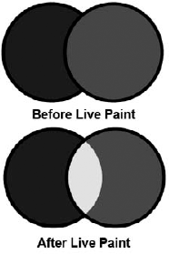
Figure 9.51. You can convert objects to Live Paint objects using the Object
You cannot convert some object types, such as type and brushes, to Live Paint objects directly, but if you first convert them to paths using the Type
Note
You also can convert bitmap images to Live Paint objects by first using the Live Trace feature. Simply select the bitmap image, and choose the Object
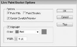
Once converted, you can fill faces using the Live Paint Bucket tool (shortcut, K) and select them with the Live Paint Selection tool (Shift+L). Moving the mouse over a face with either tool highlights the face boundaries in red. Double-clicking either tool opens a dialog box of options, as shown in Figure 9.52. With these options, you can select to apply only Paint Fills, only Paint Strokes, or both. You also can change the highlight color and width. And you can preview the swatch color as part of the cursor. You also can use the Live Paint Bucket and Live Paint Selection tools to convert the selected objects to Live Paint objects.
If you double-click a Live Paint face with the Live Paint Bucket tool, all contiguous faces are filled across an unstroked edge. A triple-click changes all faces with the same color to the current fill. Holding down the Shift key switches the current settings in the Live Paint Bucket Options dialog box. For example, if you select Paint Fills, the Shift key causes the Paint Strokes option to be selected.
If you want to add more paths to the existing objects to divide it into even more faces, simply double-click the face with the Selection tool where you want to add another path to isolate the face. Then draw the path using one of the drawing tools, and double-click the art board again with the Selection tool (not the Live Paint Selection tool, just the normal Selection tool). The new path is added to the Live Paint objects, and new faces are created. The new face won't be visible until you use the Live Paint Bucket to change the face attribute.
You also can add new paths to an existing Live Paint group using the Object

Perhaps the coolest feature of a Live Paint object is that when you edit it, all the filled faces readjust to maintain their filled colors. Figure 9.54 shows the same two overlapping circles where the points have been selected and moved. Live Paint is smart enough to adjust the objects so that the faces remained filled.

If you need to apply a feature that Live Paint can't handle, such as transparency, you can dissolve the Live Paint group using the Object
Expanding a Live Paint group maintains the current fills and strokes but separates each edge and face into a separate object. Figure 9.55 shows an expanded Live Paint group, which has had each edge and face moved using the Group Selection tool.
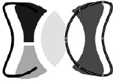
If two paths don't exactly meet in the Live Paint group, a fill could spill over into the next face when you click with the Live Paint Bucket tool. To prevent this, you can manually edit all paths to eliminate existing gaps. To see any gaps in the current Live Paint group, choose View
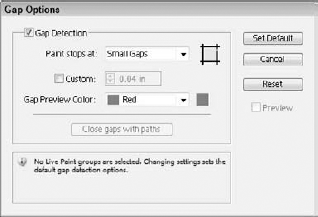
Figure 9.56. You can use the Gap Options dialog box to close any gaps in the current Live Paint group.
STEPS: Working with Live Paint
Open an Illustrator document. With Illustrator open, choose File
Create a Live Paint group. Select all the overlapping objects, and choose the Object
Fill the Live Paint faces. Select the Live Paint Bucket tool from the Toolbox, and change the fill color to blue. Then click the square backgrounds. Change the fill color to yellow, and click the elliptical portions of the kite. You can speed the coloring of each portion by double-clicking the area that needs to be filled. This automatically fills each face where a stroke doesn't exist. The resulting kite is shown in Figure 9.57.
Add a path to the Live Paint group. Click and hold the Rectangle tool flyout until the Star tool is selected. Then drag in the art board to create a simple 5-pointed star object. Drag the star object with the Selection tool to the center of the top kite circle. Drag over the entire kite object, and choose the Object


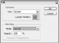
Although fills and strokes are mainly applied to objects, they also may be applied to a pixel selection in Photoshop using the Edit
Note
If the Edit
The Stroke dialog box, shown in Figure 9.60, also includes options to specify the width and color of the stroke and whether to place the stroke inside, in the center, or outside of the selection.

Paths in the Paths palette in Photoshop also may be filled and stroked using the Fill Path and Stroke Path palette menu commands. The Fill Path dialog box includes the same settings used to fill a selection along with a Feather Radius value and an Anti-aliased option.
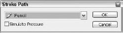
The Stroke Path dialog box, on the other hand, includes a single option to select the Tool that is used to stroke the path, as shown in Figure 9.61. The options include all the various drawing and editing tools including Pencil, Brush, Eraser, Clone Stamp, Smudge, and so on.
Color plays an important part in any design, and the color features found in the Creative Suite 4 applications are amazingly diverse. Whether your documents are designed for print, CD-ROM, or a Web site, colors are easily selected and manipulated. You add colors to objects using fills and strokes, and you paint images using an assortment of tools.
Color is a major part of any design, and in the CS4 applications, you can access several different color models, including RGB, Web Safe RGB, CMYK, HSB, and Grayscale. Which color model you use depends on where you intend the artwork to end up. For example, the RGB color mode works well if you intend your design to be viewed on a computer monitor via a CD-ROM. However, if the design is going to be placed on a Web site, you'll want to consider using the Web Safe RGB color mode. For designs that are to be printed, the CMYK color mode is appropriate. The good news is that you can switch among these different color modes at any time using the Color palette menu.
Tip
In Illustrator and InDesign, you can hold down the Shift key while clicking the color bar in the Color palette toggles through the different color modes.
Tip
InDesign's color selector also can specify colors using the Lab color model.
This color mode is used to display colors on a computer monitor. Inside a CRT computer monitor (or television) are thousands of tiny red, green, and blue electron streams that project beams of red, green, or blue light, one for each pixel. By changing the intensity of each gun, you can control the resulting color of each pixel. LCD screens use a different technique to produce the same colors by controlling the alignment of crystals. The RGB color mode produces colors by mixing together red, green, and blue. The amount of each color determines the final color. Figure 9.62 shows the Color palette with the RGB color mode selected.
Note
The RGB color system is additive, meaning that the higher color values drive the color toward white. This is different from the subtractive color system used by the CMYK color mode, in which the higher color values drive the color toward black like mixing inks that act as filters to remove frequencies of light. The more of each color you have, the closer you get to black because you are removing light.
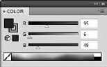
Figure 9.62. The Color palette for the RGB color mode includes separate sliders for Red, Green, and Blue values.
Within Photoshop, Illustrator, InDesign, and Flash, you can create colors by specifying the amount of each color to use. The values range from 0, which includes none of that color, to 255, which includes a full amount. A separate value is listed for red, green, and blue. By altering these color values, 16.7 million different colors are possible for an 8-bit image and high bit depths offer even more colors.
For example, a color that includes a value of 255 for red, 0 for green, and 0 for blue would be pure red. Amounts of 255 of each color produces white, and amounts of 0 of each color produces black. Equal amounts of each of the three colors produces gray. Mixing red and green produces yellow, mixing green and blue produces cyan, and mixing red and blue produces magenta.
The Web Safe color mode is a subset of the RGB color mode that includes a limited palette of colors displayed more consistently without dithering on a browser regardless of the system used to view the design. Figure 9.63 shows the Color palette with the Web Safe color mode selected. Notice how the color values are displayed as hexadecimal numbers, which are numbers based on 16 digits instead of 10 digits in our normal counting system. The hexadecimal system is more efficient for computers because more values can be expressed using only 2 digits instead of 3.
Because of the difference between system color sets on Mac and Windows systems, some Web-page colors viewed on one system look dramatically different from the same Web page viewed on a different system. To fix this problem, a 216-color palette that includes colors that are common between Windows and Mac systems has been defined as a Web Safe palette. Using these colors ensures that the colors are consistent between different systems.
Note
Although systems that display only 256 colors are rare with the modern monitors and video cards, Web-safe colors are important for ensuring that specific colors such as logos are consistent across all systems.
HTML code refers to Web colors using the hexadecimal (base-16) numbering system. The results are two-digit numbers instead of three, but the value is still the same. The hexadecimal equivalents to the RGB numbers are displayed in the Color Picker dialog box.
The HSB color mode defines colors using the common physical properties of hue, saturation, and brightness. This color mode is useful if you need to change the brightness or a color without changing its hue. Hue is measured as a position on a circular color wheel, which ranges from 0 to 360 degrees. Red is found at 0 (and 360) degrees, yellow at 60 degrees, green at 120 degrees, cyan at 180 degrees, blue at 240 degrees, and magenta at 300 degrees. Figure 9.64 shows the Color palette with the HSB color mode selected.
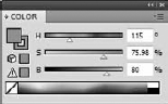
Colors found in between are a mixture of the primary colors. For example, orange is represented by 48 degrees between red and yellow. Colors on the opposite side of the color wheel are inverted pairs—red and cyan, yellow and blue, and green and magenta.
The Saturation value determines the purity of the color. This value can range from 0 to 100 percent. Reducing a color Saturation value is analogous to mixing the color with white. Colors with a 0 percent Saturation value are displayed as pure white, regardless of the Hue value.
Brightness is the opposite of saturation. It ranges from 0 to 100 percent and measures the amount of black that is mixed with the color. Reducing the brightness makes the color darker. HSB colors with a Brightness value of 0 are pure black.
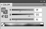
The CMYK color mode is based on cyan, magenta, and yellow inks that are mixed to create colors. The K stands for black. This color mode is used for designs that you print. Figure 9.65 shows the Color palette with the CMYK color mode selected.
Note
The letter B typically represents the color blue, so K represents black. Although you can create black by mixing full equal portions of cyan, magenta, and yellow inks, the actual result from mixing these inks is a muddy brown, so true black is printed using black ink.

Figure 9.65. When the CMYK color mode is selected, the out-of-gamut warning icon appears for all colors that are out of the CMYK gamut.
You specify CMYK colors by providing a percentage between 0 and 100 percent for each color. Digital printers typically print CMYK documents using a four-color process where the sheets are run once for each color.
The Grayscale color mode converts all colors to grayscale values. This color mode is used for black and white images. Grayscale values are represented by a single brightness value that ranges from 0 to 100 percent with 0 percent being white and 100 percent being black. When colors are converted to grayscale, the color's luminosity value determines its grayscale value. Figure 9.66 shows the Color palette with the Grayscale color mode selected.

Note
Photoshop and InDesign actually includes an additional color mode called the Lab color mode. The L stands for lightness, the a is for the green-red color wheel axis, and the b is for the blue-yellow color wheel axis. This color mode makes it intuitive to work with the luminance of an image.
Colors may be applied to an object's fill or stroke using the Fill and Stroke boxes in the Toolbox. Fill and Stroke boxes also are found in the Color palette (refer to Figure 9.67) for convenience, which lets you choose specific colors using color values or select a color by simply clicking the color bar.
Note
To see the Fill and Stroke boxes and the color values for the selected color mode in the Color palette, select the Show Options palette menu command.
When the mouse is moved over the top of the color bar, the cursor changes to an eyedropper. Clicking the color bar changes the color for either the Fill or Stroke box, whichever is active.
Tip
If you drag one of the color value sliders, except for Black, with the Shift key held down, all color values scale along with the selected color. This works for all color modes except for the HSV and Grayscale.
Beneath the Fill and Stroke boxes in the Color palette are two icons that appear as you drag about the color bar. The top icon is the Web Safe color warning. This icon looks like a simple cube and informs you that the current color is not a Web Safe color. The color swatch next to the icon displays the nearest Web Safe color, and clicking it changes the current color to the nearest Web Safe color.
Beneath the Web Safe color icon, another icon may appear that looks like a yellow triangle with an exclamation point inside it. This icon appears when the current color is out-of-gamut and is not available in the CMYK color mode. The color swatch next to it is the nearest color available in the CMYK color mode, which means it may be printed. A similar color swatch appears next to the Out of Gamut warning icon.

Figure 9.67. The Web Safe color warning icon and the Out of Gamut color warning icon both appear within the Color palette.
The Color palette menu in Illustrator also includes two commands (Inverse and Complementary) for quickly locating the inverse or complementary color to the current color. An inverse color is opposite the current color in the color wheel for the current color model; a complementary color offers a decent amount of contrast to the original color.
If you double-click the Fill box in the Toolbox in Illustrator and Photoshop, a Color Picker, shown in Figure 9.68, appears. Using the Color Picker, you may select any color by manipulating the color values or by selecting a color from the color spectrum. Flash requires only a single click to access the Color Selector.
The color values for several color modes are displayed in the Color Picker. Toward the top of the Color Picker dialog box, the Web Safe and Out-of-Gamut icons appear just like the Color palette along with color swatches that you can click to reset the color. The Only Web Colors option in the lower-left corner limits the colors in the color spectrum so only Web Safe colors are displayed. Figure 9.69 shows the Color Picker with this option enabled.
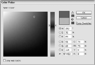
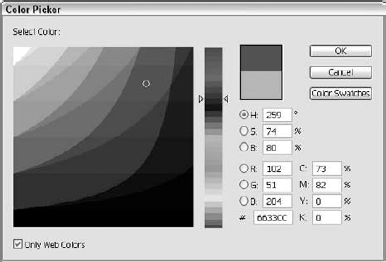
Figure 9.69. With the Only Web Colors option enabled, the total number of colors is severely limited.
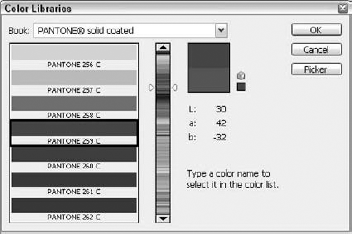
The Color Swatches button (called Color Libraries in Photoshop) opens a dialog box of distinct named colors that coordinate to the color swatches available in the Swatches palette. In Photoshop, you can choose from a specific color book at the top of the dialog box. These color books include several Pantone specific color libraries like the one shown in Figure 9.70.
In addition to using the Color Picker, you can select colors from within the image using the Eyedropper tool. The Eyedropper tool works differently in Photoshop and Illustrator. The tool in Photoshop, Flash, Fireworks, and Dreamweaver is used to get only color. But in Illustrator and InDesign, the Eyedropper tool can retrieve appearance attributes, character style, and paragraph style.
Dragging over an image with the Eyedropper tool changes the Foreground color. In the Options bar, you can use the color of the point directly under the tool or to sample a 3×3 or a 5×5 grid around the cursor. Holding down the Option/Alt key while dragging in the image with the Eyedropper tool changes the Background color.
Tip
The Eyedropper tool may be selected temporarily while using one of the painting tools by holding down the Option/Alt key.
The Color Sampler tool is available as a flyout under the Eyedropper tool. Using this tool, you can click four different points in the image and the color values for those points are displayed in the Info palette. Only four color sample points may be placed in an image, but you can drag these points to new locations as needed or clear them all using the Clear button in the Options bar.
You can use Illustrator's Eyedropper tool to gather property values from one object and apply them to another object. The specific properties that are gathered by the Eyedropper tool is set using the Eyedropper Options dialog box, shown in Figure 9.71, which is opened by double-clicking the Eyedropper tool.
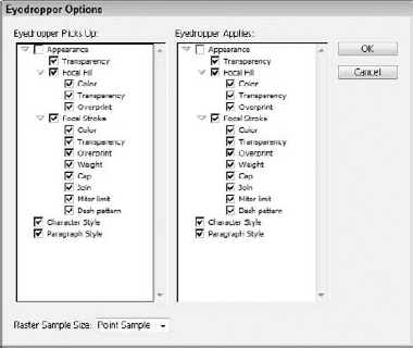
The attributes that are picked up by the Eyedropper tool are immediately applied to the selected object. These attributes may include Appearance attributes such as Transparency, Fill Color, Stroke Color, Stroke Weight, Cap and Join Type, and even Character and Paragraph Style. If you hold down the Shift key, then only the color attribute is gathered and holding down the Alt (Option) key toggles between the applied version of the eyedropper. You also can gather color from the computer's desktop using the Eyedropper tool by clicking and holding in the Illustrator document window and then dragging around the desktop.
The Eyedropper Options dialog box also lets you sample raster images using a point sample, a 3×3-pixel sample or a 5×5-pixel sample.
The Eyedropper tool in InDesign works the same as the one in Illustrator. It is used to both gather and apply selected attributes. Double-clicking the Eyedropper tool opens a dialog box of options, shown in Figure 9.72, that may be gathered using the Eyedropper tool.
Clicking an object gathers all the attributes for that object, and the cursor changes so the Eyedropper is pointing in the opposite direction and appears to be filled. Clicking another object applies the attributes. You can click multiple objects while the Eyedropper is filled. To fill the Eyedropper with new attributes, hold down the Option/Alt key while clicking another object.

Choosing the right colors for a design often can make or break a design. Illustrator's Live Color interface includes a set of controls that alter all the colors in a document. It also is used to give you color hints and lets you experiment with different color groups.
The Live Color dialog box, shown in Figure 9.73, shows all the colors used in the current selection and lets you edit or reduce these colors. The Live Color dialog box is opened using the Edit
You also can select to change specific colors by clicking the color in the New column or by clicking one of the random color shift buttons. If you click the arrow between the Current Colors column and the New column, you can preserve an existing color from being changed. The Preset drop-down list lets you choose to use a specific color library or reduce the total number of colors to a specified number.
At the top of the Live Color dialog box, the Edit button switches the dialog box to a separate panel that shows all the selected colors in a color wheel, as shown in Figure 9.74. This panel lets you see how the colors in the current group are related. You can change any of the colors by dragging the color indicator around the color wheel. If you click the Link button, all colors move together when one is moved.
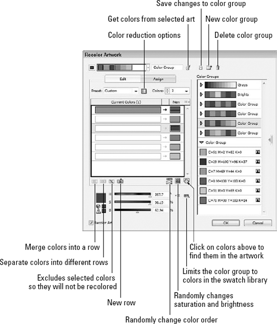
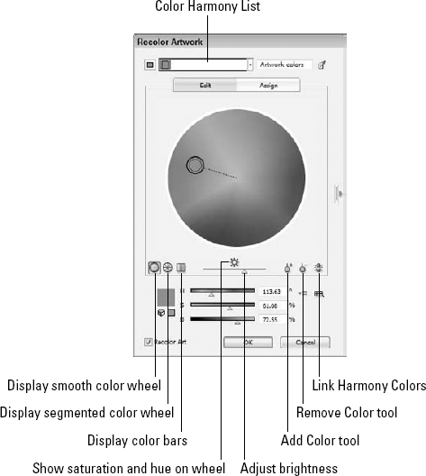
Figure 9.74. The Edit panel of the Live Color dialog box lets you switch among several color harmony settings.
The Color Harmony list includes several design options based on the first color swatch. The available design schemes include the likes of Complementary, Split Complementary, Analogous, Monochromatic, Shades, Triad, Compound, Tetrad, High Contrast, and Pentagram. If you need some inspiration in your color design, these options are a great place to start.
Another helpful tool in Illustrator is the Color Guide palette, shown in Figure 9.75. As you use colors in your document, the Color Guide automatically suggests harmonious colors that match the current colors in the document. From the palette menu, you can save the colors as swatches, access the Variation Options dialog box, or switch between Tints/Shades, Warm/Cool, and Vivid/Muted color schemes. The Variation Options offer controls for changing the number of steps and a slider for altering the amount of variation in the suggested colors. You can also select the same Harmony Rules that are listed in the Live Color interface from the drop-down list at the top of the palette.
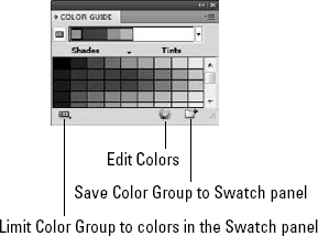
Adobe understands all the issues surrounding color and has endowed the print-oriented CS4 applications including Photoshop, Illustrator, InDesign, Acrobat, and Bridge with color-management methods including a Color Settings dialog box accessed under the Edit menu.
This dialog box, shown for Photoshop in Figure 9.76, lets you select from several different color setting profiles. Using the same profile, settings, and color management policies for all applications produces consistent color output regardless of the application or system. Some of these color setting profiles include North America General Purpose Defaults, U.S. Prepress Defaults, Web Graphics Defaults, as well as profiles for Europe and Japan.
The Color Settings dialog box also lets you define a custom color setting. Custom settings may be saved and loaded for use across applications. Adobe Bridge can synchronize the color management settings for the print-oriented CS4 applications.
Note
The Color Management features found in the various CS4 applications are covered in Chapter 5.
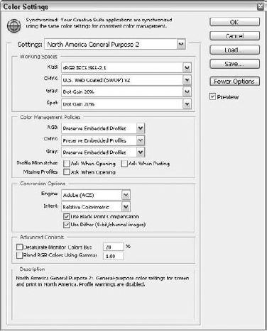
When a light source shines on an object, the point closest to the light is usually the brightest and the light intensity gradually decreases the further you get away from the light. This decrease in light intensity over distance is called attenuation, and it's common for most light sources.
Simple light attenuation may be simulated in Illustrator, InDesign, Photoshop, and Flash using gradients. Gradients let you specify two or more colors, and the gradient interpolates between these two colors by gradually changing between the specified colors.
In addition to color, gradients may be applied as an object fill by clicking the Gradient button in the Toolbox or by clicking the gradient in the Gradient palette. The Gradient palette, shown in Figure 9.77, includes controls for specifying gradient colors and behavior.
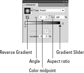
You can expand the Gradient palette in Illustrator and InDesign to show some additional controls including a Type drop-down list, which includes two gradient Types: Linear and Radial. Photoshop goes even further offering Linear, Radial, Angle, Reflected, and Diamond gradient options.
Linear gradients run in a straight line from the color specified at one end of the gradient to the color specified at the other end. For Linear gradients, you can specify an Angle value, which determines the direction that the gradient runs.
Radial gradients place the gradient color specified at one end of the Gradient palette at a specified point, and the changing colors are displayed as concentric circles around this designated point. Figure 9.78 shows examples of linear and radial gradients.
The color bar at the bottom of the Gradient palette lets you specify gradient colors and the midpoints between those colors. The color stop icons appear below the gradient bar; the midpoint markers appear as diamond icons above the gradient bar. To change the position of either of these icons, drag them to the left or right. The position of the icon is displayed in the Location field as a percentage of the entire gradient.
To change the color of a color stop, select the color stop and choose a new color from the Color palette. When a color stop is selected, the small arrow above it turns black.
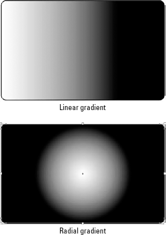
Note
You can select a color swatch to use in the gradient color stop by holding down the Option/Alt key while clicking a color swatch, or you can drag swatch colors to the gradient color stops. But if you select a gradient color stop and click a color swatch, the color in the swatch is selected and the gradient goes away.
To add new color stops to a gradient, click below the gradient bar where you want to position the new color stop, drag a color swatch from the Swatches palette to the gradient bar, or hold down the Option/Alt key and drag an existing color stop to the side. A new midpoint icon is added for each new color stop that is added.
Although the Angle may be specified for Linear gradients in the Gradient palette, the Gradient tool (found in the Toolbox) is useful for interactively specifying the gradient angle. With the gradient tool selected, click a selected object where you want to position the leftmost gradient color and drag to where you want to place the rightmost gradient color. This lets you control precisely how the gradient runs across an object.
If the line that is dragged with the gradient tool lies at an angle, the Angle value is set accordingly. Holding down the Shift key while dragging constrains the angle to 45-degree increments.
The Gradient tool also may be used to cause a single gradient to span multiple objects. To do this, select all the objects, apply a gradient fill to them, and then drag with the Gradient tool across the selected objects.
The Gradient panel includes values for specifying the gradient's angle and aspect ratio. With the Gradient slider marker, you can set the gradient's location and opacity. If you double-click on the slider marker, then you can set the color for the slider. If you click below the color bar, then you can add a new slider.
STEPS: Creating and Applying a Custom Gradient
Create a new Illustrator document. With Illustrator open, choose File
Apply a radial gradient. With the star selected, click the Gradient button at the bottom of the Toolbox. Then in the Gradient palette, select the Radial type. The star is filled with a radial gradient, as shown in Figure 9.79.
Change the gradient colors. With the Swatches palette and the Gradient palette opened at the same time, drag a bright yellow color swatch from the Swatches palette to the first color stop at the left end of the gradient bar in the Gradient palette. Then drag a red color swatch from the Swatches palette to the last color stop at the right end of the gradient bar in the Gradient palette. The colors are immediately applied to the star, as shown in Figure 9.80.
Add a new gradient color stop. Click under the middle of the gradient bar to create a new color stop. This new color stop uses the intermediate color from the gradient bar. Drag a black color swatch from the Swatches palette to the new color stop in the Gradient palette. The new color stop changes the color applied to the star dramatically, as shown in Figure 9.81.
Reduce the black color stop spread. To reduce the spreading color of the black color stop, select the midpoint icons above the gradient bar on either side of the black color stop and drag them toward the black color stop. This limits the spread of the black color within the gradient, as shown in Figure 9.82.
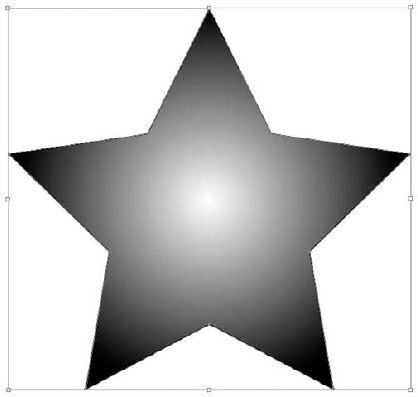
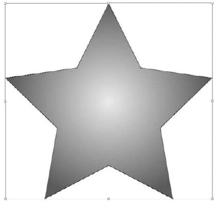
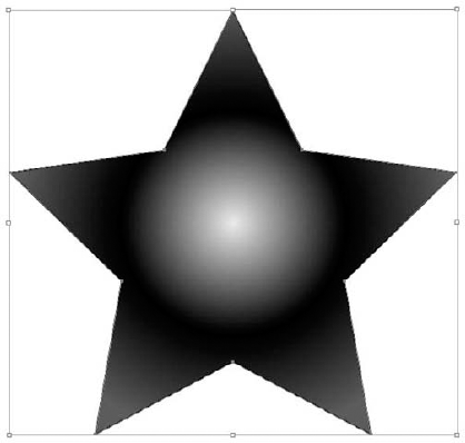
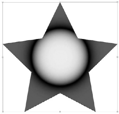
You can change vector objects within Illustrator to mesh objects using the Mesh tool or the Object

The Appearance drop-down list includes Flat, To Center, and To Edge options. The Flat option colors the entire object with a single fill color. The To Center option adds a white highlight at the center of the object that gradually changes to the fill color at the edges. The To Edge places a white highlight at the object's edges that gradually changes to the object's fill color at its center. The Highlight percentage sets how white the highlight color is.
Warning
Mesh objects in Illustrator take up lots of system resources and can greatly slow down your system if they're overly complex. It's best to keep mesh objects simple if you experience performance problems.
Figure 9.84 shows three simple rectangles that have been converted to meshes by choosing Object
The Mesh tool is used to place the intersecting mesh points within an object. After clicking to place an intersecting point on an object, you can choose a color from the Color palette to apply as a gradient color for the new intersecting point. Clicking the object again with the Mesh tool creates another new intersecting mesh point. Holding down the Shift key while clicking an object creates an intersecting mesh point without changing its fill color.

Objects that have a gradient fill applied to them may be expanded to a gradient mesh object with the Object
After you create objects, you have several ways to edit them. An object's position and orientation may be altered using the transformation tools, its properties may be changed using the various palettes such as Illustrator's Appearance palette, and filters and effects may be applied to change the object in many different ways.
Note
Transformations are covered in Chapter 12. Applying filters and effects is covered in Chapter 13.
In addition to these editing methods, there are several other ways to edit objects including joining, slicing, and cutting paths; blending objects; distorting objects; and using the Pathfinder features.
Paths are created by dragging with tools such as the Pen, Paintbrush, Pencil, and Line Segment tools, but several additional tools let you edit paths.
Drawing freehand paths with the Pencil tool often results in jagged lines, but these lines are easily smoothed over with the Smooth tool. The Smooth tool is a flyout under the Pencil tool. Dragging over a freehand line with the Smooth tool gradually removes all the sharp changes in the line and smoothes it. Double-clicking the Smooth tool opens a dialog box where you can set the Fidelity and Smoothness values for the tool. The Path Erase tool, a flyout under the Pencil tool, may be used to delete a portion of the selected path. By dragging over the selected path with the Path Erase tool, the section that is dragged over is deleted.
Figure 9.85 shows a rough line drawn with the Pencil tool. The second line has been smoothed with the Smooth tool, and the portions of the last line were erased using the Erase tool.
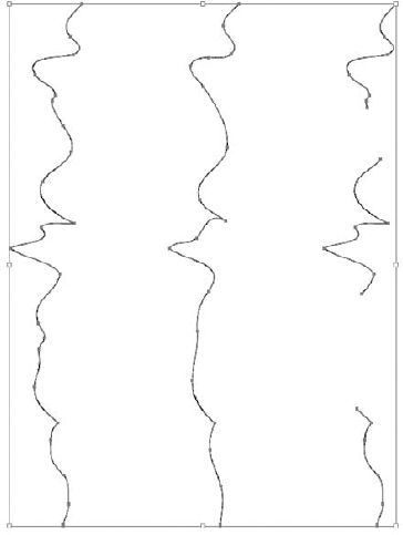
The Reshape tool (located as a flyout under the Scale tool) lets you select an anchor point, several anchor points, or a line segment as part of a path and drag it while maintaining the overall shape of the path. This causes the entire path to move along with the selected portion. By comparison, anchor points and line segments selected with the Direct Selection tool are moved independent of the entire path; the Scale tool moves all points equally in the scaled direction.
To select anchor points or line segments with the Reshape tool, simply click or drag over the portions of the path that you want to select. The relative distance between the selected points won't change as you drag the path; adjacent anchor points move in proportion to the distance from the selected points.
Figure 9.86 shows three duplicate paths. The left line was drawn with the Pencil tool. The middle path is a duplicate that was scaled horizontally, and the right path is a duplicate that was modified using the Reshape tool. Notice how the scaled path is distorted, while the reshaped path maintains its path details.
The following is a list of other ways to edit paths:
Splitting paths: You can use the Scissors tool to cut a path in two. You don't need to select the path to split it. The location where you click with the Scissors tool determines where the path is split.
Joining and averaging paths: If the endpoints of two different paths are selected with the Direct Selection tool, you can make a straight line connect these two endpoints by choosing Object
Converting strokes to filled objects: You can convert strokes into filled objects by choosing Object
Offsetting paths: Choosing Object
Note
The Control panel includes many ways to edit paths including converting points, aligning and distributing points, cutting and closing paths, and deleting points.
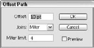
Cleaning up a document reduces the file size. Choosing Object

The Angle Threshold value determines the corner smoothness. If the angle of a corner point is less than the Angle Threshold value, the corner isn't smoothed.
Tip
When you enable the Preview option, the total number of points in the original and simplified curves is displayed.
The Straight Lines option simplifies the curve using only straight lines; the Show Original option displays the original line in the art board.
Choosing Object

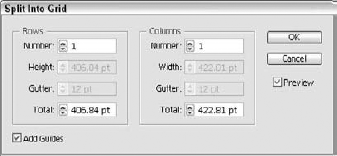
Sometimes shape editing calls for removing or separating a portion of an object. You can split an object in several ways:
Note
You use the Slice tool to separate images and objects into slices. Each slice can hold vector or raster sections. By slicing documents, you can move them to the Web as separate files that work together.
Using the Knife tool: The Knife tool (located as a flyout tool under the Scissors tool) is a freehand tool that cuts through a selected object. Objects split where you drag the tool. Holding down the Option/Alt key drags a straight line.
Cutting holes in shapes: You can use a closed shape as a cookie cutter to punch out the selected shape from all the objects beneath it. To do this, position the cutting object on top of the object that you want to cut, and choose Object
Compound objects are created when two or more selected paths or shapes are combined to create a single object. Compound objects are different from grouping objects. Objects within a group may have different attributes, but all the paths or shapes in a compound object share the same appearance attributes. Even though compound objects are combined to make a single object, the individual items still may be selected using the Direct Selection or Group Selection tools, just like groups. Compound objects may be restored to their original components using the Release menu command.
In addition to compound paths, Illustrator can create compound shapes using the Pathfinder palette, shown in Figure 9.91. Open this palette by choosing Window
In addition to the palette menu command, you also can use the icon buttons found in the Pathfinder palette to add to the shape area, subtract from the shape area, intersect shape areas, or exclude overlapping shape areas. The Subtract button removes from the first object all shape areas that overlap the first object. The Intersect button leaves only those areas that are common to all selected shapes. The Exclude button removes all areas of the objects that overlap another shape.
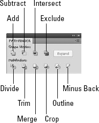
After a compound shape is created, you can change the shape mode for any of the objects that make up the compound shape by selecting it with the Direct Selection tool and choosing a new button in the Pathfinder palette.
Whenever objects are combined to create a compound shape, the appearance attributes of the topmost object are applied to the compound object.
Note
Compound shapes use the appearance attributes of the topmost shape. Compound paths use the appearance attributes of the bottommost path.
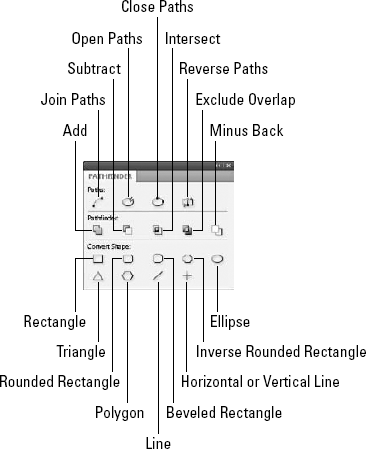
The Blend tool (W) may be used to morph the shape, path, color, or style of one object to another. To use this tool, click an object and then on a second object to blend to. Several intermediate objects appear between the two objects. Figure 9.93 shows a blend that moves between different shapes, strokes, and fills.
Blend objects are selected as a single object, but you may select individual objects that make up a blend object by using the Direct Selection tool. Changing a selected shape or color of either of the objects that make up the blend also updates the intermediate objects.

Double-clicking the Blend tool opens the Blend Options dialog box, shown in Figure 9.94, where you can select a Spacing option of Smooth Color, Specified Steps, or Specified Distance. When the Smooth Color option is selected, Illustrator determines the number of steps needed to make a smooth color transition between the two blend objects. For the Specified Steps and Specified Distance options, you can enter the number of steps or the distance between steps.

Figure 9.94. The Blend Options dialog box lets you define the number of steps between each blend object.
The Blend Options dialog box also lets you set the Orientation to be either Align to Page or Align to Path. The Align to Page option orients all the blend objects relative to the art board; the Align to Path option orients the blend objects relative to the blend's spine path.
When a blend is made between two objects, a straight path connects the two objects. With the Direct Selection tool, you can select this path and add anchor points to it with the Add Anchor Point tool or by choosing Object
In addition to the Blend tool, you also can blend two selected objects by choosing Object
The line connecting two blend objects is called the spine. You may choose Object
A clipping mask is a closed object positioned over the top of objects that are to be clipped. With all these objects selected, choosing Object
When a file is placed in Illustrator, a Mask button appears on the Option bar that lets you use the placed file as a clipping mask. The Options bar also lets you access the mask, the content or both. Also, when aligning to a clipping mask, the alignment uses the clip instead of the extents of the content. This makes it easier to align clipping masks to other objects in the document. Clip masks also hide clipped content and can be accessed in Isolation mode.
There are several different ways to distort objects with the Liquify tools and with Envelope Distort commands.
Illustrator includes several tools that you may use to distort selected objects. You use these tools by dragging over the selected objects with the selected tool. The longer you drag with the selected tool, the greater the effect. Figure 9.95 shows a simple circle that has been distorted using each of these Liquify tools. These tools collectively are called the Liquify tools and include the following:
Warp tool (Shift+R): Stretches object paths by pushing or pulling them.
Twirl tool: Causes paths to be twirled.
Pucker tool: Sucks paths toward the cursor.
Bloat tool: Pushes path edges away from the cursor.
Scallop tool: Adds arcs and barbs to a path edge.
Crystallize tool: Adds spikes to path edges.
Wrinkle tool: Wrinkles the edge paths with details.
Note
Most of the available Liquify tools also may be applied as filters and effects, which are covered in Chapter 13.

Double-clicking a Liquify tool opens a dialog box of options, like the Pucker Tool Options dialog box, shown in Figure 9.96. Using this dialog box, you can set the Width, Height, Angle, and Intensity of the tool's brush. You also can set the individual settings for the selected tool. The Show Brush Size option changes the cursor to an outline of the brush.

Envelopes are preset or selected shapes into which an object is distorted to fit inside. Choosing Object
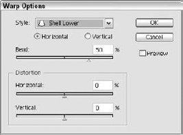
Most of these preset envelope shapes are applied horizontally or vertically by a certain Bend amount. You also can specify the Horizontal and Vertical Distortion amounts.
You apply the envelope as an editable mesh by moving its points with the Direct Selection tool. To apply a mesh to the selected object with a specified number of rows and columns, choose Object
Choosing Object
Choosing Object
Just as when editing objects, several tools and commands are useful when editing images.
Image sizes are set when a document is first created or loaded into Photoshop, but you can cut out a portion of the image using the Crop tool or the Crop and Trim commands found in the Image menu.
Using the Crop tool: With the Crop tool (C), you can drag on the portion of an image that you want to keep. This selected area is marked with a bounding box that is moved, scaled, and rotated by dragging on the handles at their edges and corners. When the crop area is correctly positioned and oriented, double-click with the Crop tool within the selected area, click the Commit button on the Options bar or press the Return/Enter key, and the image is cropped to the selected area.
Cropping and trimming an image: You also may crop an image using a selection made with one of the default selection tools with the Image
Tip
A quick and easy way to crop and trim is with the Crop and Straighten Photos script located in the File
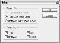
The Transparent Pixels option trims all the transparent pixels along the image edges. The Top Left Pixel Color and Bottom Right Pixel Color options trim all pixels that match the color of the top-left or bottom-right pixels. You also can select to trim just along the top, bottom, left, or right of an image.
You can create and use objects in all the various CS4 applications. To create objects, tools and menu commands are used.
Tools that create objects include the Pen, Type, Line Segment, and Shape tools. You create freehand path objects with the Paintbrush and Pencil tools. The Paintbrush, Pencil, and Paint Bucket tools apply paint to the canvas in Photoshop.
Most of the CS4 applications include tools to select objects and images. These tools include Shape tools like Photoshop's Marquee tools and Freehand tools like the Lasso tool. Objects and images with similar areas are selected using the Magic Wand tool.
Fills and strokes offer a way to add color to objects. Pixel selections also may be filled and stroked. Objects also may be filled with gradients and patterns as well as colors. Live Paint offers options for automatically filling discreet faces.
Color is applied using the Color palette, the Color Picker, and color swatches. Illustrator can also applied colors using the Color Guide, Live Color, and Live Paint.
The CS4 applications deal with several different color models, including RGB, HSV, CMYK, Grayscale, Lab, and Web Safe RGB colors. The Live Color dialog box lets you use preset color schemes.
Illustrator, InDesign, Photoshop, and Flash can apply linear and radial gradients as fills and may be used to create custom patterns.
Often-used items are saved in libraries. Libraries include symbols, styles, swatches, and brushes.
Each of the CS4 applications includes various tools and commands for editing objects and images, including tools and commands to combine objects and split and distort objects.