When Adobe first introduced the concept of filters in Photoshop, it was a risky move. To allow other developers to access the inner workings of the Photoshop graphics engine and develop their own filters to alter images was brilliant or a huge mistake. History has now validated that the move was, indeed, brilliant.
Filters are found mainly in Photoshop, but Illustrator has taken the concept one step further with the introduction of effects. Effects are essentially filters applied in memory, allowing them to be edited or even removed at any time from the Appearance palette without affecting the rest of the attributes. This same benefit can be realized in Photoshop using Smart Filters. Both Photoshop and Illustrator include filters and effects.
The variety of filters and effects found in both Photoshop and Illustrator are quite diverse, covering everything from unique brush strokes and object distortion to color adjustment and even 3-D effects.
Many filters in Photoshop are moving into complex interfaces like the Filter Gallery that lets you explore, preview, and apply many filters at once. Other common filter interfaces include the Extract, Liquify, and Pattern Maker interfaces.
All the filters that may be applied to an image are contained within the Filter menu. Filters are applied to a selection or to the active layer if there is no selection. The top menu command in the Filter menu always lists the last filter command used. It includes a keyboard shortcut of
Note
Some filters may be applied only to images with the RGB color mode selected, and some filters may be applied only to an 8-bit image. Filters that cannot be applied to the current image are disabled. In Photoshop, choosing Image
The Filter Gallery lets you apply multiple filters at once or a single filter multiple times. To open the Filter Gallery, choose Filter
Note
All the filters listed in the Filter Gallery also include their own menu commands in the Filter menu. Selecting a filter menu command for a filter that is part of the Filter Gallery opens the Filter Gallery with the selected filter highlighted.

Figure 13.1. The Filter Gallery includes most of the Photoshop filters and lets you apply many filters at once.
The Filter Gallery interface is divided into three different panes. The left pane is the preview pane that displays the current layer or selection. The middle pane includes thumbnails of all the available filters. Clicking a filter highlights it in gray and selects the filter. The right pane includes all the settings for the selected filter.
Note
Although the Filter Gallery includes many filters, it doesn't include all filters available in Photoshop.
Moving the mouse over the Preview pane changes the cursor to a hand. Dragging with this hand cursor pans the preview image within the pane. The buttons and pop-up menu at the bottom of the Preview pane are used to zoom in, zoom out, and select a specific zoom percentage. The pop-up menu also includes an Actual Pixels option, which displays the image at its actual size of 100%; a Fit in View option, which zooms the image so the entire image is visible in the Preview pane; and a Fit on Screen option, which maximizes the Filter Gallery to fill the entire screen.
Clicking the Show/Hide button in the top-left corner of the Settings pane hides the filter thumbnails and uses that space to increase the size of the Preview pane, as shown in Figure 13.2.
The Filter pane is organized into several different categories of filters including Artistic, Brush Strokes, Distort, Sketch, Stylize, and Texture. Similar categories are found in the Filter menu. The category that includes the current selected filter is highlighted in bold.
Clicking the small arrow to the left of the filter category name expands the category to reveal all the filters within that category. Clicking on filter thumbnail selects the filter and displays all its settings in the Settings pane. The selected filter's name is displayed at the top of the interface along with the zoom percentage, and the background of its thumbnail is highlighted dark gray.
The Settings pane includes a drop-down list of all the filters. Filters may be selected from this list when the filter thumbnails are hidden. Below this list, the settings for the current selected filter are displayed. Changing any of these settings alters the effects of the filter, and the Preview pane shows the changes.
At the bottom of the Settings pane is a list of filters applied to the preview listed in the order in which they are applied to the image. If you click a new filter, it replaces the currently selected filter. To apply an additional filter to the image, click the New Effect Layer button at the bottom of the Settings pane. This freezes the current selection and adds a new filter layer to the interface. The name of this filter layer is that of the filter that was applied.
If you click the Visibility icon to the left of the filter layer name to toggle it off, the Preview pane is updated to show the image without the filter. Selecting the filter layer and clicking the Delete Effect Layer button at the bottom of the Settings pane deletes filter layers.
If multiple filter layers exist in the Filter Galley, you can rearrange them by dragging one layer above or below another. Changing the order in which filters are applied can drastically change the resulting image.
When you're satisfied with the resulting preview, click OK to apply the listed filter layers to the image. Click Cancel to exit the Filter Gallery without applying any filters.
STEPS: Using the Photoshop Filter Gallery
Open an image in Photoshop. Within Photoshop, choose File

Open the Filter Gallery. Choose Filter
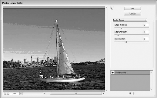
Select a filter. Click the Artistic category, and select the Poster Edges filter. In the Settings pane, set the Edge Thickness to 2, the Edge Intensity to 1, and the Posterization to 2. Figure 13.3 shows the image with this single filter applied in the Filter Gallery.
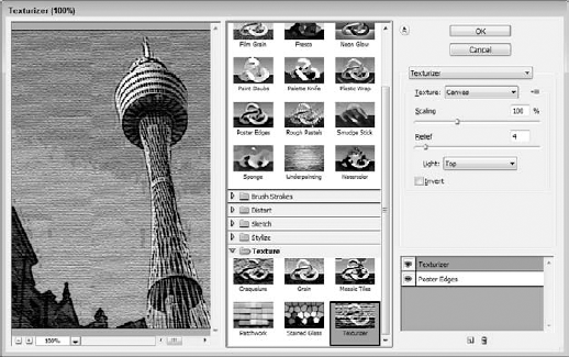
Add another filter. Click the New Effect Layer button at the bottom of the Settings pane to add another filter to the image. Click the Texture category, and select the Texturizer filter. In the Settings pane, select the Canvas option from the Texture drop-down list. Set the Scaling value to 100%, the Relief value to 4, and the Light option to Top. Figure 13.4 shows the resulting image in the Preview pane.
Apply the selected filters. Click OK to apply the two selected filters to the image. Figure 13.5 shows the resulting image with the filters applied.


In addition to the filters included in the Filter Gallery interface, Photoshop has several other filters that are applied using the Filter menu.
Most of these filters have their own dialog boxes of settings that appear when the filter's menu command is selected. Some of the filters don't have any dialog boxes that open. The menu commands that have an ellipsis (...) following their menu command open a dialog box.
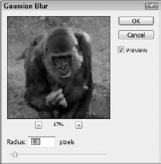
Most filter dialog boxes include a Preview option and a Preview pane, like the Gaussian Blur dialog box, shown in Figure 13.6. The Preview pane gives you an idea of what the filter effect is before it's applied to the entire image. By clicking and dragging the image in the Preview pane, you can reposition the portion of the image that is displayed in the Preview pane. The plus and minus buttons underneath the Preview pane let you zoom in and out of the image. Enabling the Preview option applies the current filter settings to the entire image.
Warning
Applying some filters, even in Preview mode, can take some time depending on the calculations involved in the filter and the size of the image.
The Filter
The first three Blur filters—Average, Blur, and Blur More—are applied without a dialog box. Average takes the average of all the selected colors and applies that average color to the entire selection. The Average filter is useful when used with the Magic Wand tool to create a single area with a single color.
The Blur filter removes any noise along hard edges by averaging the colors along these hard edges, resulting in a smoother overall image. The Blur More filter does the same but to a greater extent.
The Box Blur filter blurs the selected area by taking the average color value of pixels within a square area. The Radius value determines the size of the box.
The Gaussian Blur filter opens a dialog box where you can specify the amount of blur to add to the image. The Radius value determines the size of the groups of pixels that are averaged.
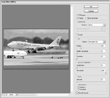
The Lens Blur filter opens a dialog box, shown in Figure 13.7, that lets you simulate a depth-of-field effect where the camera is focused on a particular point in the scene and all objects farther or nearer than that point are blurred in relationship to their distance from the focal point.
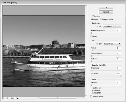
The Source field lets you base the focal point on the image's Transparency value or an included Depth Mask. The Iris Shape field lets you choose the shape of the defined averaged areas where the blur is applied as well as its Blade Curvature and Rotation. You also can specify values for Specular Highlights and Noise.
The Motion and Radial Blur filters let you control the direction of the blur lines. The Motion Blur filter specifies an Angle and a Distance value to blur the image linearly, as shown in Figure 13.8. The Radial Blur filter blurs the image in concentric circles about a point that you can select in the Radial Blur dialog box, also shown in Figure 13.8.
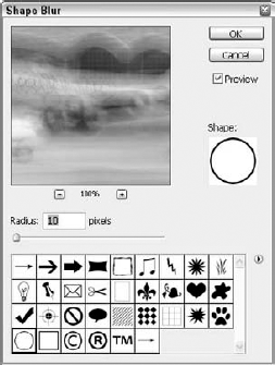
The Shape Blur filter blurs the image using a selected shape. The Shape Blur dialog box, shown in Figure 13.9, includes several default options, but you can load new shapes using the pop-up menu. The Radius setting determines the size of the shape that blurs the image. Notice in the figure how the circular shape causes details in the image to be blurred in circular patterns.
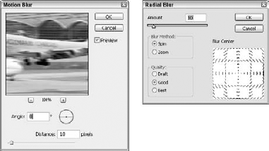
Figure 13.8. The Motion Blur and Radial Blur dialog boxes let you blur the image using linear or radial lines.
The Smart Blur filter is unique in that it lets you blur areas of similar colored pixels based on the Threshold value. The Mode may be set to Normal, Edge Only, or Overlay Edge. The Edge Only and Overlay Edge options color the edges white based on the Threshold value. Figure 13.10 shows the Smart Blur dialog box. In the Preview pane, similar areas have been blended together.

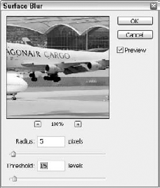
You can use the Surface Blur filter to blur the image while preserving its edges. This has the effect of softening the entire image while maintaining the image details. The larger the Radius setting, the more that the pixels bleed into one another and the Threshold value sets the limit for edges that are blurred. Figure 13.11 shows the Surface Blur dialog box.
STEPS: Blurring an Image's Background
Open an image in Photoshop. Within Photoshop, choose File
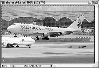
Select the background. Click the Quick Selection tool, and click on the airplane and drag to the edge of the airplane to roughly select the background. After making an initial selection, hold down the Alt/Option key and deselect any portions of the airplane that were accidentally selected. Figure 13.12 shows the selected background area.
Apply the Lens Blur filter. Choose Filter
The Filter Gallery interface includes three filters in its Distort category, but the Filter
The Displace filter distorts the image based on a loaded displacement map. The displacement map defines how the pixels move, with black areas marking a negative displacement and white areas marking a positive displacement. Figure 13.14 shows a patterned image with the Displace filter applied using the simple displacement map.
Note
Displacement maps must be saved using the PSD file format. Some sample displacement maps are found in the plug-insdisplacement maps directory.
Note
The Lens Correction filter, found in the Filter
The remaining Distort filters all open a dialog box where you can enter the amount of distortion to apply. Most of these dialog boxes, like the Twirl dialog box shown in Figure 13.15, include a graphical representation of what the distortion looks like. In some cases, such as for the Shear filter, the graphical representation may be manipulated to define the distortion.
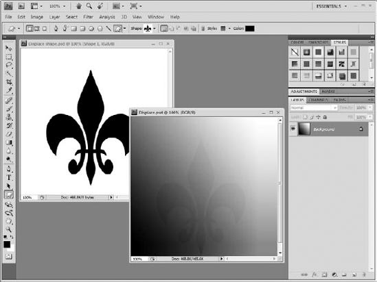

Figure 13.15. The Twirl dialog box includes a Preview pane and also a graphical representation of the distortion that is applied.
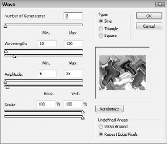
Of all the Distort filters, the Wave filter dialog box, shown in Figure 13.16, includes many unique settings for distorting the image such as selecting the Wave Type as Sine, Triangle, or Square, as well as a Randomize button.
When noise is added to an image, it randomly alters the colors of many of the surrounding pixels, making the image grainy. But it also can be used to blend areas that have been retouched, making them appear more realistic. The Filter
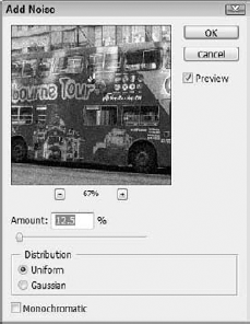
The Add Noise filter opens a dialog box, shown in Figure 13.17, where you can specify the amount of noise to add to the image. The Uniform option randomly adds noise about the selected value, and the Gaussian option adds noise using a bell-shaped average curve. The Monochromatic option causes the noise to be black and white.
The Despeckle filter doesn't open a dialog box, but it removes noise from the image. It also detects edges to maintain the details of the image. The Median filter also removes noise from the image by replacing the brightest and darkest pixels with a median-colored pixel.
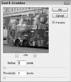
Most scratches and dust irregularities are small enough that they may be removed using the Dust & Scratches filter. This filter looks for small abrupt changes that are as small as the designated Radius value and with a given threshold. This filter applies a general blurring of the entire image. Figure 13.18 shows the dialog box for this filter.
Adding noise to an image can soften an image by including a grainy feel, but having too much grain can affect image clarity. Some cameras can add film grain to an image and digital cameras add digital noise. Saving images to the JPEG format also can add unwanted noise and can reduce the image to the point that ugly artifacts and distortions appear. Photoshop includes a filter that can help remove noise from an image. It also is found in the Filter
The Reduce Noise dialog box, shown in Figure 13.19, includes a preview pane along with several settings. You can save and recall settings using the Settings dialog box. You also can switch the dialog box between Basic and Advanced displays. The Basic display includes settings for Strength, Preserve Details, Reduce Color Noise, and Sharpen Details. You also have an option to Remove JPEG Artifact:

Strength: Removes luminance noise in all channels that cause the image to appear grainy.
Preserve Details: Controls how aggressively the image edges and details are affected.
Reduce Color Noise: Removes any random color pixels that exist in the image caused by noise.
Sharpen Details: Increases the sharpness lost by noise reduction.
Remove JPEG Artifacts option: Enables the filter to deal with the blocky artifacts caused by saving the image to the JPEG format. These artifacts appear because of the compression algorithm used by the JPEG format.
If you determine that the luminance noise exists in only a single channel, you can switch to the Advanced display to make a Per Channel pane available. This pane displays the Red, Green, and Blue channels and lets you set the Strength and Preserve Details for only the selected channel.
The Filter
The shapes of the grouped pixels in each of these filters are slightly different, each creating a unique stylized look. For example, the Color Halftone filter changes each pixel group into a circle based on its brightness, the Crystallize filter changes groups of pixels into an irregular polygon shape, the Mosaic filter changes each grouping into a square, and the Pointillize filter groups pixels into solid dots. Figure 13.20 shows examples of several of these filters.

The process of rendering involves additional computations that alter the image in new and interesting ways. Using the filters in the Render category enables you to create clouds, fibers, and lighting effects like lens flares.
The Render filters include two filters for creating clouds—Clouds and Difference Clouds. The Clouds filter replaces the current image or selection with a random distribution of pixels using the Foreground and Background colors.
Tip
Holding down the Option/Alt key while choosing Filter
The Difference Clouds filter is similar, but instead of replacing the image, it blends the clouds with the image or the selection using a Difference blending mode, which inverts the colors of the image. Figure 13.21 shows an image where the Clouds filter has been applied to the left half, and the Difference Clouds filter has been applied to the right half.
Note
You can learn more about the various blending modes in Chapter 9.
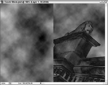
Figure 13.21. The Clouds filter has been applied to the selection on the left of this image, and the Difference Clouds filter has been applied to the right half of the image.
The Render
Lens flares are lighting anomalies that appear when you point a camera at a bright light. The Lens Flare filter opens a dialog box, shown in Figure 13.23, where you can click in the Preview pane to position the lens flare. You also can set the brightness of the lens flare and choose one of four lens types.
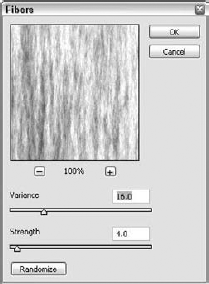
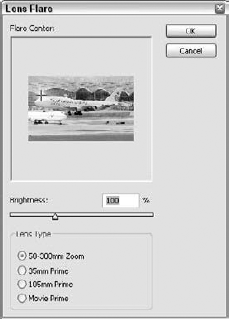
Figure 13.23. The Lens Flare dialog box lets you position the flare by dragging within the Preview pane.
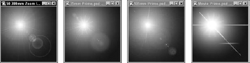
Each of the various lens types creates a different pattern of streaks, rings, and glows. You can see results of each lens type in Figure 13.24.
Of the various filters in the Render category, the Lighting Effects filter offers the most functionality. This filter may be applied only to RGB images using the Filter
Warning
The Lighting Effects filter requires a substantial amount of memory, and if your system doesn't have enough memory available, a warning dialog box appears. You can make more memory available using the Edit
When the Lighting Effects filter is applied, the Lighting Effects dialog box, shown in Figure 13.25, is displayed. Using this dialog box, you can add multiple lights to shine upon the image shown in the Preview pane.
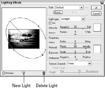
Figure 13.25. The Lighting Effects dialog box lets you position multiple lights around the image and change their settings.
To add a light to the image, click the Light icon at the bottom of the Preview pane and drag it into the Preview pane, or hold down the Option/Alt key and drag from an existing light to duplicate the light. All lights appear in the Preview pane as white dots. These lights may be repositioned by dragging the white dots to a new location.
When a light is selected in the Preview pane, an ellipse that represents the light's range is displayed. By dragging on its handles, you can change the light's range. Holding down the Shift key while dragging these handles constrains the ellipse to change only a single dimension.
Lights are deleted by dragging their white dots to the Trash Can icon beneath the Preview pane.
The Light Type field lets you select from three different light types: Directional, Omni, and Spotlight. A Directional light shines light rays from a distant source, and all its rays are parallel much like the Sun. An ellipse represents a Spotlight and controls the Spotlight's angle and direction. A Spotlight decreases in intensity the further from its source it gets. An Omni light, represented by a circle, casts light equally in all directions, much like a light bulb.
Each light is enabled or disabled using the On option. Each light type also has an Intensity value, which may be positive or negative. A negative light value actually pulls light away from the image. Each light also can have a color, which is specified by the color swatch to the right of the Intensity setting. Click the color swatch to open a Color Picker where you can change the light's color.
When the Spotlight type is selected, one end of the ellipse acts as the source and is the brightest point (or the darkest if the Intensity value is negative). The Focus value sets how much of the ellipse is filled with light.
The Properties values determine how the light interacts with the image surface. The Gloss value determines how shiny the surface is and how much the light reflects. The Material setting controls whether the light color (Plastic) or the image color (Metallic) gets reflected. The Exposure setting is a multiplier for the light, and the Ambience setting controls the background lighting in the image. The color swatch to the right of the Properties is for the ambient light color.
The Texture Channel field lets you select a channel and use it to emboss the image by raising the channel relative to the remaining pixels.
With all these controls, it may be difficult to configure an effective lighting setup. Photoshop includes several default Style settings from which you can select. These presets include a variety of settings, and you can save your own presets using the Save button at the top of the dialog box.
STEPS: Applying Lighting Effects
Open an image in Photoshop. Within Photoshop, choose File
Open the Lighting Effects dialog box. Choose Filter
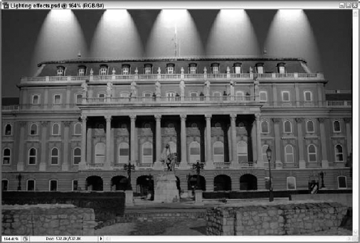
Select a lighting style. From the Style drop-down list at the top of the dialog box, select the Five Lights Down style. This adds several lights to the Preview pane, as shown in Figure 13.26.
Configure the lights. Click one of the white dots to select a light in the Preview pane. Notice that the Intensity value is already at maximum, but the lighting is still too dark. Drag the Ambience slider up to 25 to increase the overall light for the scene. Then click OK to apply the lighting to the image. Figure 13.27 shows the resulting image.

The Sharpen filters are used to enhance the details of blurry images by increasing the contrast of edges. Choose Filter
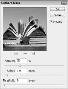
The Unsharp Mask filter opens a dialog box, shown in Figure 13.28, that lets you adjust the amount of sharpness that is applied. This filter works by increasing the pixel contrast for areas where adjacent pixels have a value that is greater than the specified Threshold. The Radius value determines the size of the area where the pixel values are compared, and the Amount setting controls how much the contrast of adjacent pixels within the Threshold is increased.
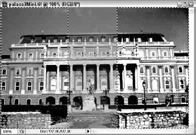
Be warned that over sharpening an image adds halos to the image edges. Images that include particularly bright colors may be oversaturated if you set the Amount setting too high. Figure 13.29 shows an image with the Unsharp Mask filter applied to different sections. The left end of the palace image has a large Radius value and a low Threshold causing the contrast to be increased for the entire section. The right end of the image has been sharpened with high Amount and Radius settings and a low Threshold setting, causing the section to be over-saturated. The middle section is unchanged.
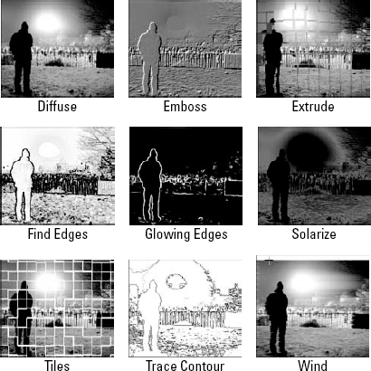
The Stylize filters apply a variety of unique effects that give an image a specific style. The filters in this category include the Diffuse, Emboss, Extrude, Find Edges, Glowing Edges, Solarize, Tiles, Trace Contour, and Wind.
The Diffuse filter moves pixels around to make the image appear unfocused. The options include Normal, Darken Only, Lighten Only, and Anisotropic. The Emboss filter colors the entire image gray and raises the image along its edges to form a relief. The Emboss dialog box lets you choose Angle, Height, and Amount values.
The Extrude filter divides the image into squares and then colors each square to look like it is rising from the surface of the image. In the Extrude dialog box, you can select to use blocks or pyramids, set the size of the squares, and set the depth that they rise to.
The Find Edges and Solarize filters are applied without a dialog box. The Find Edges filter identifies all the edges in the image and displays them as dark borders on a white background. The Solarize filter combines the image with the image's negative to produce a darkened image with inverted colors.
The Tiles filter divides the entire image into square tiles and offsets each one slightly. In the Tiles dialog box, you can select the number of tiles and a maximum offset. The Trace Contour filter outlines the edges of the image, based on brightness, and displays them on a white background. The Wind filter spreads the edges of an image in different intensities as if something were dragged over the image when it was wet. Figure 13.30 shows a sampling of the Stylize filters applied to an image.
At the bottom of the Filter menu are two miscellaneous filter categories—Video and Other. The Video filters include De-Interlace, which is used to remove interlaced lines from images captured from a video source, and NTSC Colors, which limits the color palette to those used for broadcast television.
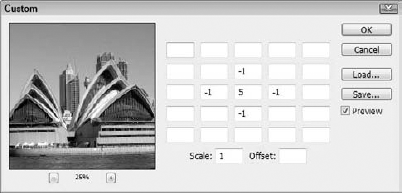
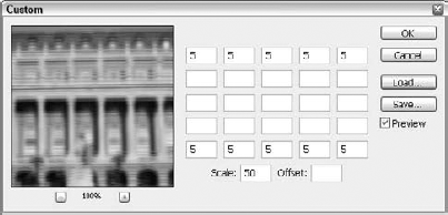
The Other category includes the Custom filter. This filter opens a dialog box, shown in Figure 13.31, that includes an array of value fields. Each text field represents the brightness value of the pixels that surround the pixel represented by the center text field. These brightness values can range from −999 to +999. The Scale value is used to divide the sum of all brightness values and the Offset value is added to the brightness values after scaling. By entering custom values into these text fields, you can create your own custom filter. These custom filters may be saved and reloaded as needed. The custom filters are saved with an ACF extension.
The Other category also includes a High Pass filter, which highlights all the sharp color changing edges. The Minimum and Maximum filters look at a grouping of pixels defined by the Radius value and remove the brightest (or darkest) pixel from the group.
The Other category also includes the Offset filter. This filter offsets all the pixels in an image, making the image edges appear within the image interior. This filter often is used to mask the image edges to make an image tileable.
STEPS: Creating a Custom Filter
Open an image in Photoshop. Within Photoshop, choose File
Open the Custom dialog box. Choose the Filter
Enter filter values. Enter a value of 5 in each cell in the top and bottom rows of the Custom dialog box. Then set the Scale value to 50, as shown in Figure 13.32.
Save the custom filter. Click the Save button, and save the custom filter with the name Double exposure. The resulting image is shown in Figure 13.33.

At the bottom of the Filter menu is a separator line. All third-party filters installed appear below this line. Photoshop, by default, includes one third-party filter category. The Digimarc filters enable you to embed a digital watermark into an image to secure copyright information.
At the top of the Filter menu, along with the Filter Gallery, are several additional interfaces that let you interactively filter an image or a selection. These interfaces include the Liquify interface and the Vanishing Point filter.
The Liquify interface may be used to stretch and distort images and image selections as if they were placed on putty. To open the Liquify interface, shown in Figure 13.34, choose Filter
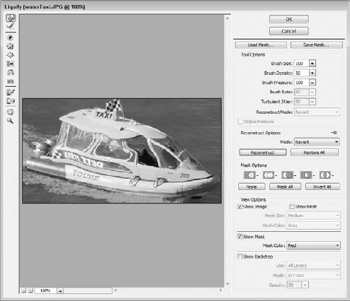
Moving the cursor over the Preview pane where the image is displayed reveals the outline of a brush. The brush options include Size, Density, Pressure, Rate, and Turbulence Jitter. Each of these options is set using the controls listed to the right.
The various liquify tools are displayed in a toolbar to the left of the Preview pane and include the following:
Forward Warp tool: This tool is used to push pixels in a forward direction as you drag the mouse. Holding down the Shift key while dragging moves the mouse in a straight line.
Reconstruct tool: This tool is used to remove any liquify effects from the image and restore the brushed area to its original look.
Twirl Clockwise tool: This tool is used to rotate the pixels about the center of the mouse in a clockwise direction. Holding down the Option/Alt key while dragging rotates the pixels in the counterclockwise direction.
Pucker tool: This tool is used to move the pixels toward the center of the brush.
Bloat tool: This tool is used to move the pixels away from the center of the brush.
Push Left tool: This tool is used to move the pixels to the left when you drag upward. Dragging the mouse downward moves the pixels to the right. Rotating the mouse in a clockwise direction increases the areas. Rotating in a counterclockwise direction reduces the area. Holding down the Option/Alt key forces the mouse to drag straight up or down.
Mirror tool: This tool is used to copy the pixels being dragged over to the opposite side of the brush. Holding down the Option/Alt key while dragging flips the effect to the other side.
Turbulence tool: This tool is used to randomly move pixels underneath the brush area.
Freeze Mask tool: This tool is used to paint a mask layer onto the Preview pane.
Thaw Mask tool: This tool is used to erase a mask layer onto the Preview pane.
Hand tool: This tool is used to drag the Preview pane to reposition the visible portion of the image. Double-click to fit in window.
Zoom tool: This tool is used to zoom in on the image in the Preview pane. Holding down the Option/Alt key lets you zoom out. You also can zoom in on the image using the small plus and minus icon buttons in the lower-left corner. Double-click to see 100%.
Dragging with any of the Liquify tools in the Preview pane distorts the image. These distortions may be undone using the Reconstruct tool. The Reconstruct tool has several modes including Revert, Rigid, Stiff, Smooth, and Loose. Each of these modes reconstructs the image in a different manner. Pressing the Restore All button returns the image to its original state.
At any time during the modifications, you can use a mask to lock an area from any changes. The Mask Options dialog box includes buttons to replace, add, subtract, intersect, or invert the current mask selection, transparency, or layer mask.
The View Options let you toggle on and off the image, the distortion mesh, the mask, and the backdrop. The backdrop is the faded version of the original image.
STEPS: Using the Liquify Interface
Open an image in Photoshop. Within Photoshop, choose File
Set the Foreground color. Click the Fill box in the Toolbox, and select a dark red color from the Color palette.
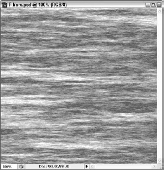
Apply the Fiber filter. Choose Filter
Rotate the canvas. Choose Image
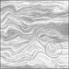
Use the Liquify interface. Choose Filter
Drag with the Liquify tools. Select the Forward Warp tool, and drag up and down throughout the image to create some ripples. Select the Bloat tool, and drag small lines up and down to expand areas of the image. Finally, select the Turbulence tool, and drag throughout the image to add some turbulence to the image. Figure 13.37 shows the final distorted image.

Painting walls in Photoshop is easy enough when the wall is a solid color, but if you're trying to add a patterned texture to the wall, it can be difficult to match the perspective view as you apply the paint. A work-around is to apply a Perspective transformation to the texture before applying the transformation, but you need to match the area exactly or apply it to a different layer that you can clean up later.
Photoshop CS4 has a unique way of handling this complex problem. The Vanishing Point interface, under the Filter menu, has a dialog box that opens with the current image in its preview pane (Alt+Ctrl+V in Windows; Option+
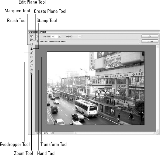
Figure 13.38. The Vanishing Point interface lets you define perspective planes by clicking the plane's four corner points.
After you define a perspective plane, you can use the tools located in the upper-left corner of the Vanishing Point interface to edit the perspective plane, paint, or transform selections. When a tool is selected, its settings appear in the Control panel at the top of the interface. Each of these tools works the same and has the same keyboard shortcuts as the original interface.
STEPS: Using the Vanishing Point Interface
Open an image in Photoshop. Within Photoshop, choose File
Open the Vanishing Point filter. With the image selected, choose Filter
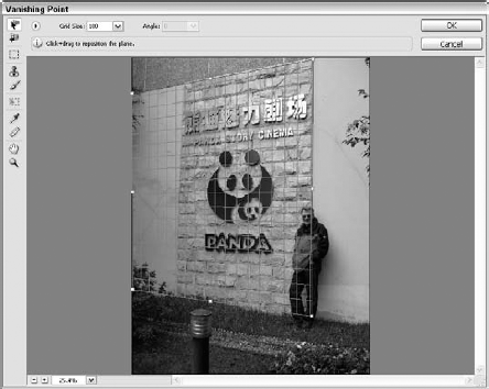
Click each of the corners of the perspective plane. When the Vanishing Point interface is first opened, the Create Plane Tool is selected. Click each of the four corners that make up the perspective plane. The plane is highlighted with a grid as shown in Figure 13.39.
Select a paint area. To control where the paint is applied, click the Marquee tool in the upper-left corner of the interface and drag over the left portion of the perspective plane where the gray wall is.
Use the Stamp tool. Select the Stamp tool, and hold down the Alt/Option key while clicking the lower portion of the rock texture under the Panda sign. Then paint a new rock face in to the left of the Panda sign. Continue to reset the Stamp tool's origin, and repaint the rest of the left gray wall. Figure 13.40 shows the new perspective painted rock wall.
Tip
Another way to accomplish this is to simply turn off the align option. With the align option off, the stamp tool keeps going back to the same location automatically.
Note
The stamp tool in the Vanishing Point interface shows a preview of the stamp data, which is very helpful.
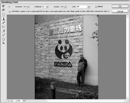
Figure 13.40. With the Vanishing Point interface, the Stamp tool copies image portions while maintaining the perspective view.
The preceding tutorial is a simple example of a single plane vanishing point image, but the Vanishing Point dialog box can deal with multiple grids, enough to recreate a cube. If you hold down the Ctrl/Command key and pull on an edge, a linked grid is created that is positioned at 90 degrees from the original grid. If you click and drag an edge handle with the Alt/Option key held down, you break the 90 degree lock on the linked grids and allow the grids to swing into new positions.
Any new artwork that is pasted into the Vanishing Point dialog box is automatically wrapped around all of the defined grids. Furthermore, if you are using Photoshop CS4 Extended, then you can export the 3D grids and textures to the DXF and 3DS formats for use in a 3D modeling package.
Filters are applied with an Opacity value of 100%, making the filter take over the image completely. But you can make the applied filter effect transparent and even specify a blending mode by choosing Edit
This command opens the Fade dialog box, shown in Figure 13.41, where you can specify an Opacity value and select a blending mode.
Note
For more details on the various blending modes, see Chapter 9.

Most of the default filters found in Photoshop also are available in Illustrator under the Effect menu. These effects are located at the bottom of the Effect menu underneath the Illustrator default filters.
Note
These same Photoshop filters also are found in Illustrator in the Effect menu, allowing them to be applied as effects.
Warning
Most Photoshop filters work only in RGB mode, not in CMYK mode.
Smart Filters are any filters that are applied to a Smart Object. The key benefit of Smart Filters is that you can change the settings, hide and even remove them in a nondestructive way. This shields the image from any permanent changes and lets you experiment with the filters without having to worry about messing up the image.
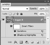
To apply a Smart Filter, simply select a Smart Object layer in the Layers palette and apply a filter. Any of the Photoshop filters can be used except for the Liquify, Lens Blur, and Vanishing Point filters. Once applied, the Smart Filter appears directly below the Smart Object layer in the Layers palette, as shown in Figure 13.42.
Note
Creating a Smart Object allows Shadow/Highlights and Variations to be applied as smart filters using the Image
Flash includes a set of filters, but filters in Flash can be applied only to text, buttons, and movie clips. To apply a filter, open the Filters panel and click the plus icon to select a filter. The available filters include Drop Shadow, Blur, Glow, Bevel, Gradient Glow, Gradient Bevel, and Adjust Color. Flash can also use filters imported from Fireworks. Filters also can be copied and pasted between objects.
In addition to object filters, Flash includes a category of Timeline effects that can be applied to motion sequences. These effects include the ability to make objects expand, transform, explode, and transition over time.
The drawback to using effects is that they take up valuable memory, and applying too many of them can significantly slow down the system. If you have lots of RAM, this shouldn't be a problem.
Tip
If memory becomes an issue, the Appearance panel lets you turn on and off individual effects to help control processing load.
At the top of the Effect menu are two commands for instantly repeating the last applied effect and for recalling the dialog box used in the last applied effect.
All applied effects show up in the Appearance palette, as shown in Figure 13.43, where they may be selected, edited, and removed at any time.
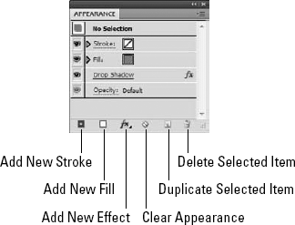
After an effect is applied to an object, the same effect is applied by default to all new objects that are created. To make new objects appear without these effects, click the New Art Has Basic Appearance button at the bottom of the Appearance palette.
Effects can be removed from the selected object by selecting an effect in the Appearance palette and choosing the Remove Item palette menu command or by clicking the Delete Selected Item button at the bottom of the Appearance palette. To remove all effects, click the Reduce to Basic Appearance button. This command causes all effects to be removed, but it doesn't change the stroke or fill settings. Clicking the Clear Appearance button removes all effects and sets the stroke and fill colors to None.
Using the Visibility toggle, you can turn each appearance item on or off.
If multiple items are selected, then you can edit the attributes for each of the selected items all at once. This is a very powerful feature when combined with the select shared appearance attribute that is used in the Select Similar Object button in the Options bar.
Many effects convert the object to a raster image before the effect is applied. Actually, the conversion doesn't happen until the file is outputted or rasterized with the Rasterize command, but the object still maintains its vector outline. Choose Effect
Note
SVG filters and the Document Raster Effects Settings dialog box are covered in more detail in Chapter 23.
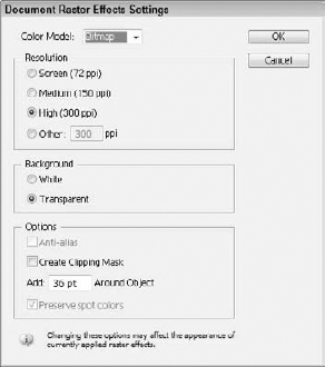
Figure 13.44. The Document Raster Effects Settings dialog box lets you specify the settings to use when an object is rasterized.
The Effect menu also includes a Rasterize menu command that opens up a dialog box with the same settings as the Document Raster Effects Settings dialog box. The settings in this dialog box are object-specific.
The Convert to Shapes effects let you change the shape of an object into a Rectangle, a Rounded Rectangle, or an Ellipse. Each effect opens a dialog box, like the one shown in Figure 13.45, where you can specify the dimensions of the new shape.
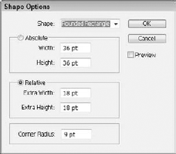
Figure 13.45. The Shape Options dialog box lets you convert shapes and bitmaps into a rectangle, a rounded rectangle, or an ellipse.
The Crop Marks effect adds crop marks to the current document based on the current selection.
Note
Crop marks created with the Crop Marks filter conform to neither the artboard crop set nor to those created with the Crop Area tool.
The Distort effects let you distort object paths in a number of different ways, including Free Distort, Pucker & Bloat, Roughen, Tweak, Twist, and Zig Zag. Each of these effects opens a dialog box where you can control the settings for the distortion.
These effects may be applied only to object paths, not to raster images, symbols, or text objects.
The Free Distort effect lets you distort a path by dragging the corner points of its bounding box. Figure 13.46 shows this dialog box.

Figure 13.46. The Free Distort dialog box lets you distort an object path by dragging the corners of its bounding box.
The Pucker & Bloat effect is used to push the center of each segment toward the object center (Pucker) or away from the object center (Bloat).
The Roughen effect may be used to add small random changes to the path as if someone scribbled with a pen. The Tweak effect also applies randomness to a path by bending each segment inward or outward. The Twist effect lets you specify an Angle value that defines how much the path is twisted about its center. The Zig Zag effect causes the path to be angled back and forth in a regular pattern.
Figure 13.47 shows each of the Distort effects applied to a simple rectangle.

There are several Illustrator Stylize effects including—Add Arrowheads, Drop Shadow, and Round Corners.
The Add Arrowheads effect may be applied only to an open path. The Add Arrowheads dialog box, shown in Figure 13.48, lets you select from a library of arrowheads for the start and end of the path.
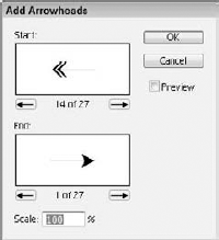
Figure 13.48. The Add Arrowheads dialog box lets you select the arrow type to use for the Start and End of a path.
The Drop Shadow effect adds a simple drop shadow to the selected object using the Drop Shadow dialog box, shown in Figure 13.49. For the drop shadow, you can select a blending mode, an opacity, offset distances, a blur amount, and a color.

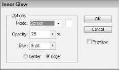
The Feather effect opens a simple dialog box where you can enter a Feather Radius amount. The Inner and Outer Glow effects open a dialog box like the one in Figure 13.50, where you can select a blending mode, a glow color, an opacity, and blur values, as well as whether the glow emanates from the center or from the edges of the object.
The Round Corner effect opens a simple dialog box where you can specify a radius to use to round the corners of the selected path.
The Scribble effect opens a dialog box, shown in Figure 13.51, where you can make a path look like it was drawn using scribbled strokes. Although the resulting line looks like it was drawn freehand, the object is still a path and maintains it vector properties.

Figure 13.51. The Scribble Options dialog box lets you specify the options to create a rough scribbled look.
At the top of the Scribble Options dialog box is a drop-down list of presets. These presets lets you choose from several different setting configurations including Childlike, Dense, Loose, Moire, Sharp, Sketch, Snarl, Swash, Tight, and Zig Zag.
The Angle setting defines the angle at which the strokes are aligned, and the Path Overlap defines how often a drawn path crosses itself. Most settings include a Variation setting that is used to specify how random the attribute is. You also can define the Stroke Width, Curviness, and Spacing of the scribble marks.
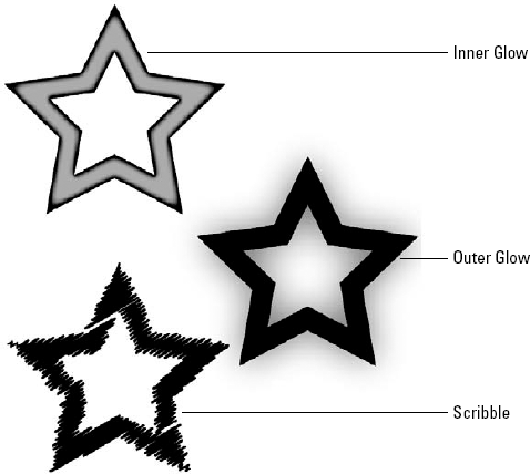
Figure 13.52 shows examples of the Inner and Outer Glow effects and the Scribble effect.
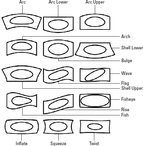
All the effects in the final category of the Effect menu open the same Warp Options dialog box, shown in Figure 13.53. Using this dialog box, you can deform the selected object into several different shapes including an Arc, Arc Lower, Arc Upper, Arch, Bulge, Shell Lower, Shell Upper, Flag, Wave, Fish, Rise, Fisheye, Inflate, Squeeze, and Twist.
The shape applied may be selected from the Style drop-down list at the top of the dialog box. For each shape, you can specify a Bend value, as well as Horizontal and Vertical Distortion values. The Bend value determines how closely the object matches the designated shape and the Distortion values skew the shape either vertically or horizontally.
Figure 13.54 shows each of the Warp styles found in the Effect

Although effects are typically found in Illustrator, Photoshop has a similar feature that may be applied to a layer called Layer Effects. A pop-up menu of Layer Effects is found at the bottom of the Layers palette.
Note
Layers and the Layers palette are covered in detail in Chapter 25.
Not only can you apply these Layer Effects to a layer, but you also can store them as Styles in the Styles palette, shown in Figure 13.55. From the Styles palette, you can apply the Layer Effects to any image or selection.

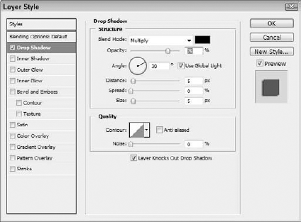
All the Layer Effects found in the Layers palette open the same dialog box, shown in Figure 13.56. This Layer Style dialog box includes a panel for each of the Layer Effects including Blending Options, Drop Shadow, Inner Shadow, Outer Glow, Inner Glow, Bevel and Emboss, Satin, Color Overlay, Gradient Overlay, Pattern Overlay, and Stroke.
Each Layer Effect may be turned on or off using the check box to the left of the effect name. To the right of the dialog box is a sample thumbnail of the defined style and a New Style button. Clicking the New Style button opens a dialog box where you can name the new style. Clicking OK adds the defined style to the Styles palette.
Each Layer Effect applied to a layer is listed in the Layers palette. Double-clicking the effect in the Layers palette opens the Layer Style dialog box where you can edit the effects settings.
InDesign includes an interface that lets you apply several of the more popular effects to InDesign objects. This interface is available from the Object
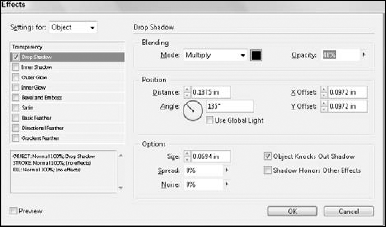
Figure 13.57. The Effects dialog box in InDesign lets you add drop shadows and many other effects to any object.
The effects selected from the Effects dialog box are applied to the selected object, which could be the object, the stroke, fill, or even text. InDesign CS4 keeps track of all the effects applied to the current selection in the Effects palette, shown in Figure 13.58. The Effects palette also lets you set the Opacity and select a blending mode independent of the Effects dialog box. You can also isolate the blending to a particular group or knockout objects inside a group.

In the Settings for option list at the top of the Effects dialog box, you can choose to apply the effect to the current Object, the Fill, Stroke, or Text. A single object can have several effects applied at the same time.
Choosing Object
Note
For drop shadows, the default blending mode, Multiply, creates the most realistic shadow and is probably the most reliable blending mode for printing.
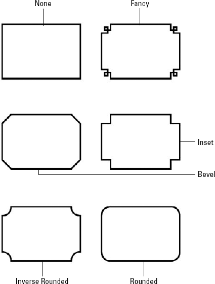
In addition to the Effects dialog box, you also can alter the container frame by choosing Object
Tip
Corner effects can be applied without the dialog box using the Pathfinder panel.
Figure 13.59 shows each of the corner effects available in InDesign.
Effects can be part of a defined Object Style allowing the effect to be added easily to other objects.
Most Photoshop filters are applied using the Filter Gallery interface. This interface includes a wide assortment of filters and allows you to preview and apply multiple filters at once.
The Filter menu in Photoshop also includes many other filters that aren't part of the Filter Gallery. These filters are selected from the Filter menu.
Photoshop includes several additional filter interfaces for working with images, including the Liquify and Vanishing Point interfaces.
Most of the Photoshop filters also may be applied to objects within Illustrator as effects.
In addition to the Photoshop filters, Illustrator also includes some effects that may be used only on vector objects.
Effects used in Illustrator show up in the Appearance palette and may be edited or removed at any time.
Layer Effects in Photoshop appear in the Layers palette and may be used to create a new style.
InDesign includes an Effects palette for applying transparency and effects to the object, stroke, fill, or text.