
Now that you are aware of all of the GPIO capabilities, you can start putting them to work. In order to do this, it is best to purchase a small breadboard and some jumper wires; this will make connecting to the outside world easier.
They are easy to find. You can purchase one at almost any electronics store or on any online electronics site. The jumper wires you want are male-to-male solderless jumper wires.
There are also many starter kits which come with breadboards and jumper cables, along with additional sensors and HW capabilities that you can use with your Arduino board. There are too many to list here; simply search Arduino starter kits on the Internet and you'll get an idea of the many choices. Just make sure they come with a breadboard and male-to-male solderless jumper wires.
Your first project will use the digital I/O pins to light up an LED. To do this, you'll need to gather two more hardware pieces. The first is a light emitting diode (LED). This is a small part with two leads that lights up when voltage is applied to it. They come in a wide variety of colors. If you want to buy them online, search for a 3 mm LED. You can also get them at most electronics shops.
You'll also need a resistor to limit the current to the LED; a 220 ohm resister would be the right size. Again, you can get them online or at most electronics shops.
If you get three LEDs and three resistors, you can exercise several of the digital I/O pins.
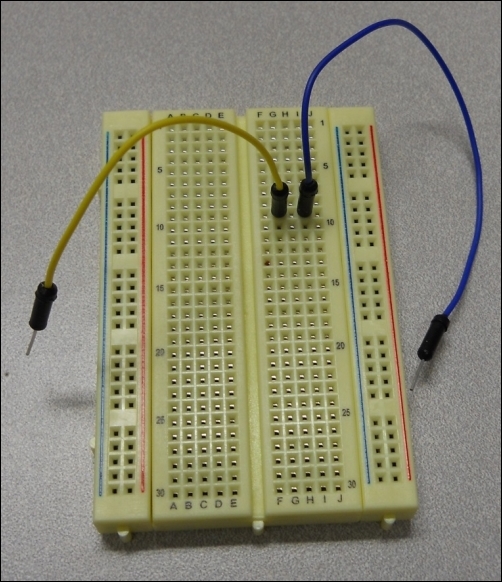
Now that you have all the bits and bobs, let's build our first hardware project. Before you plug anything in, let's look at the breadboard for a moment so that you can understand how you are going to use it to make connections. You'll be plugging your wires into the holes on the breadboard. The holes on the breadboard are connected in a unique way to make the connections you desire.
In the middle of the board, the holes are connected across the board. So, if you plug in a wire, and another wire in the hole right next to it, these two wires will be connected, as shown in the following image:
Tip
The two rows on each side of the board are generally designed to provide power, so they are connected up and down.
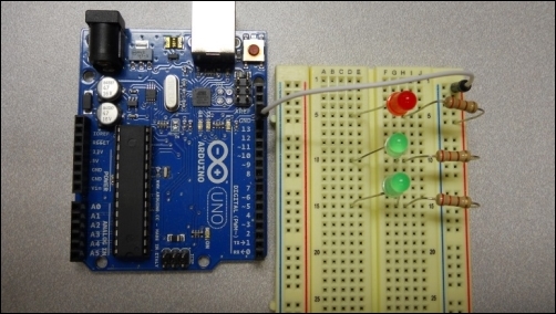
So, let's place the electronic parts on the breadboard. Place the LEDs so that one wire is on one side of the middle split of the breadboard. The direction of the LED is important; make sure the longer of the two wires is on the left side of the hole.
Now, place the resisters on the holes on one side. The direction of the resistor does not make any difference, but make sure the second wire lead is placed in the row of holes at the end of the board.
These will all be connected together, and will be connected to the GND of your Arduino using one of the jumper cables, as shown in the following image:
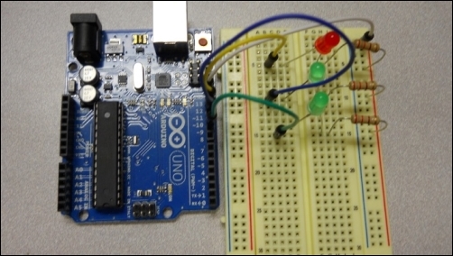
Finally, use jumper wires to connect the digital I/O pins 13, 12, and 11 to the holes on the breadboard, as shown in the following image:
Now that the HW is configured correctly, you'll need to add code to activate the LEDs.