
In Chapter 4, Accessing the GPIO Pins, you learned how to connect with the outside world using jumper wires, breadboards, and components. In this chapter, you'll learn different connection approaches to show how you can connect an additional capability to Arduino using hardware shields designed for Arduino. Specifically, I'll cover two topics: how to add a functionalities by adding hardware that is designed to plug into Arduino or shields and how to connect several types of displays to Arduino. We'll use several different types of display shields to illustrate the different communication modes that can be used to address the different types of hardware.
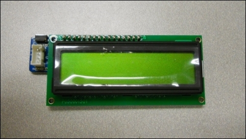
In order to understand how to use a shield, let's start with one of the most basic of the display modules available for Arduino: the serial LCD display. There are several different versions out there, but most provide a simple 2 x 16 character display that can be driven by the serial port on Arduino. This particular display is manufactured by a company called SeeedStudio; other manufacturers make a similar display. It is important that the device documents are compatible with Arduino. This means that the manufacturer has evaluated the unit and is suggesting that it is electrically and mechanically compatible with Arduino. These displays are available at most locations where Arduinos are offered.
The following image shows a picture of the display:
In order to connect this display to your Arduino, perform the following steps:
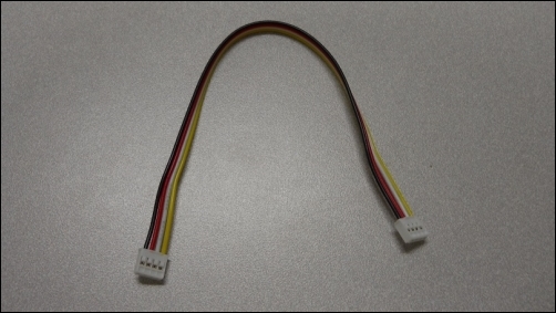
- First, you'll need some cabling. In order to connect the LCD to your Arduino, you'll need to add one more cable; this is a four-wire cable that should come with your display, as shown in the following image:
- Now, you'll need to connect the display to Arduino using these jumper wires. The following image shows a picture of the connection you'll need on the display:
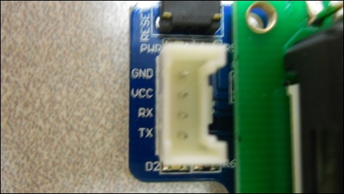
- The preceding image shows the four pins you need to connect to the display. They are GND and VCC pins, and RX and TX pins from Arduino. The VCC and GND will come from the 5 V and GND pins on Arduino. The RX and TX will come from two pins that you will specify in the code. In this case, looking at the documentation, the code will use pin 11 as RX and pin 12 as TX. So, to connect your Arduino to the display, first plug the four-wire connector into the display; then, use the male-to-male jumpers to connect the four connectors to the proper connections on the board, as shown in the following image:
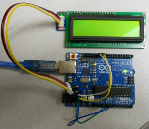
This should complete the hardware connections to the board. You should see the green and red LEDs on the display. This particular type of communication connection is a simple serial connection. The data will be transmitted onto the two pins that you will select in a serial fashion. The display will then take this serial data and translate it to the electrical drive signals needed for the display.