
Your projects may want to do more than just avoiding barriers. In this chapter, we'll go through the following topics:
- How to add a digital compass so that your projects can sense direction.
- How to add an accelerometer/gyro to your project so that you can sense the tilt and movement of your projects.
- How to add an altimeter/pressure sensor to your project so that you can sense your altitude. These can also be useful in weather prediction.
One of the important pieces of information that might be useful for your robot is its direction of travel. This could be given by a GPS unit, and we will cover how to connect one of those in Chapter 11, Using a GPS Device with Arduino. However, a GPS unit can be expensive, and it often doesn't work well inside buildings, because the GPS satellite signals don't penetrate buildings well. So, let's learn how to hook up a digital compass to Arduino.
There are several chips that provide digital compass capability; one of the most common ones is the HMC5883L 3-Axis Digital Compass chip. This chip is packaged onto a module by several companies, but almost all of them result in a similar interface. Here is a picture of one by a company called SainSmart, and it is available at a number of online retailers:
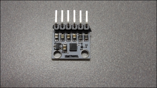
This type of digital compass uses magnetic sensors to discover the earth's magnetic field. The output of these sensors is then made accessible to the outside world through a set of registers that allow the user to set things such as the sample rate and continuous or single sampling. The x, y, and z directions are output using registers as well.
The connections to this chip are straightforward; the device communicates with Arduino using the I2C bus, a standard serial communications bus.
Note
The I2C interface is a synchronous serial interface and provides more performance than an asynchronous Rx/Tx serial interface. The SCL data line provides a clock, while the data flows on the SDA line. The bus also provides addressing so that more than one device can be connected to the master device at the same time.
On the back of the module, the connections are labeled as follows:
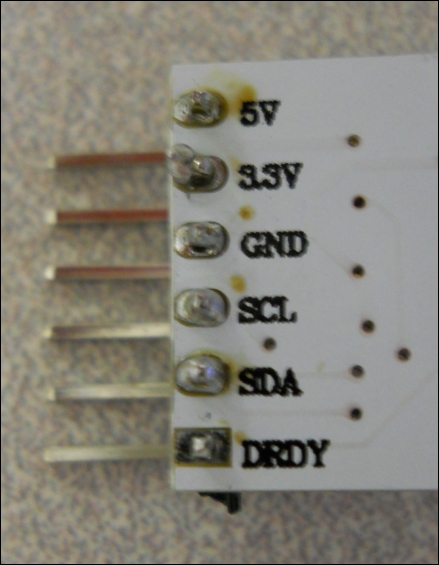
The following are the connections that you'll need to make between Arduino and the device:
|
Arduino pin |
Sensor pin |
|---|---|
|
5V |
5V |
|
GND |
GND |
|
A5 |
SCL |
|
A4 |
SDA |
Notice that you will not connect the 3.3V or DRDY (data ready) lines. Our Arduino supplies power through the 5V line instead of the 3.3V line, and the DRDY line is not needed by this library. Now, you are ready to talk with the device using the IDE.