
AutoLISP offers many features that enable you to create sophisticated programs. These include variables, functions, and conditional statements. You can use these features to easily create drawing objects. You can retrieve information about drawing objects and then modify them. As a result, getting input from the user makes your programs more interactive.
Note
AutoCAD LT does not support AutoLISP. This entire chapter is for AutoCAD only.
You can't do anything very useful in programming without using variables. A variable is a symbolic name that a program operates on. An important part of the usefulness of variables is that you can assign values to them. You use the SETQ function to name and assign a value to a variable.
The following example sets the value of 3 to a variable named radius.
(setq radius 3)
3
You can try this example in Visual LISP in the Console window. If you want to use this variable on the AutoCAD command line, precede it with an exclamation point (!). For example:
Command: !radius
3
The exclamation point before a variable evaluates the value that is stored in the variable and returns it to the command line. When you use a variable in the Console window that you've already set, you don't need the exclamation point. The Console treats everything that you type there as an AutoLISP expression.
Assigning strings to a variable is as easy as assigning numerals to a variable:
(setq name "Robin")
"Robin"
You can also nest AutoLISP expressions by placing one expression inside the other.
(setq radius (+ 2 1))
3
As explained in the previous chapter, AutoLISP evaluates LISP expressions from the innermost set of parentheses outward. In the above example, AutoLISP evaluates (+ 2 1) first and then assigns the result to the variable radius.
STEPS: Using AutoLISP Variables from within AutoCAD
Open a drawing by using the
acad.dwttemplate.Type (setq radius (+ 2 1))

Start the CIRCLE command. Specify any center point. At the
Specify radius of circle or [Diameter]:prompt, type !radiusType (setq color "green")
Type -color
Draw a circle. The circle is green because the current color is now green.
Save your drawing in your
AutoCAD Biblefolder asab35-01.dwg.
Accessing AutoCAD commands from within AutoLISP is a powerful way to automate commonly used functions. By combining access to commands from AutoLISP with variables as described in the previous section, you gain a great deal of flexibility.
In Chapter 34, when you looked at an AutoLISP routine (see Figure 34.3), you saw an example of the COMMAND function. You use the COMMAND function in AutoLISP to execute AutoCAD commands. This function treats all subsequent arguments as if they were typed at the command line interactively. When programming with the COMMAND function in AutoLISP, exactly duplicate what you would do at the command line. For example, to draw a line, you follow the steps shown in the following table. The second column shows how you would perform the same action in an AutoLISP routine.
Enter line at the command line |
|
Specify the start point for the line | Use a variable, actual coordinates, or pause for user input. |
Specify the endpoint | Use a variable, actual coordinates, or pause for user input. |
Press Enter to end the LINE command | Use an empty set of two quotation marks to represent pressing Enter either within a command or to end a command. |
For example, if you're using the variables startpt and endpt for the start point and endpoint of a line, here's how you would access the LINE command in an AutoLISP expression:
(command "_line" startpt endpt "")
Functions always begin with the DEFUN function. You can define three principal types of functions:
The type that you have been using thus far precedes the command name defined by DEFUN with
c:, which is interpreted by AutoCAD as a command and enables you to use the function by name at the AutoCAD command line. The function becomes useable like any other AutoCAD command.You can also create a function definition without preceding the name with
c:. This type is most valuable when it's called by other AutoLISP routines. If you need to execute it at the command line, you must enclose the function name in parentheses. Similarly, you can execute functions prefixed with ac:as an AutoLISP expression by enclosing the functions in parentheses, as in(c:circle3).The third type is S::STARTUP. By defining a function (usually in
acaddoc.lsp, which is loaded into every drawing) with the name S::STARTUP, every AutoLISP function in the routine will automatically execute after the drawing has fully initialized. The reason for the S::STARTUP function is to ensure that AutoLISP routines that use the COMMAND function run only after AutoCAD fully initializes the components that can execute commands.
When you create an S::STARTUP function, you need to decide where to put it. Chapter 34 briefly explained the difference between acad.lsp and acaddoc.lsp. The need for two files arose because AutoCAD includes MDI (Multiple Document Interface), which enables you to open more than one drawing at a time. For more information, see the "Automatically loading LSP files" sidebar. S::STARTUP is a great function for enhancing productivity. In this way, you can automate whatever general setup operations you normally do at the beginning of a drawing session, or for every drawing that you open.
Note
You can change the value of the ACADLSPASDOC system variable to 1 to load acad.lsp into every drawing that you open, rather than just the first drawing that you open in an AutoCAD session.
Here's an AutoLISP routine that uses both the DEFUN and COMMAND functions:
(defun c:redline (/ startpt endpt)
  (terpri)
  (setq startpt (getpoint "Select the redline start point:"))
  (terpri)
  (setq endpt (getpoint startpt "Select the redline end point:"))
  (command "_line" startpt endpt "")
  (command "_chprop" "_last" "" "_color" "red" "")
)
Here's an explanation of this routine:
The first line of this routine defines a function called
redline. Becauseredlineis preceded byc:, you can type redline at the command line when using it within AutoCAD. As you may remember from the discussion of thecircle3routine, the expression(/ startpt endpt)means thatredlinehas two local variables that are available only to this routine. These variables are used in the next two lines.The
terprifunction, on the second and fourth lines, tells AutoCAD to print a blank line at the command line. You can use this function to improve readability of the prompts. Otherwise, two or more prompts run together on one line.Reading the third line from the innermost parenthesis pair outward, AutoCAD obtains the red line's start point from the user with the prompt
Select the redline start point:and sets the variablestartptequal to that start point's value. Similarly, the fifth line obtains the red line's endpoint and sets the variableendptto that value. By first getting the start point, you see a rubber-band effect between the start and endpoints that you specify.Line 6 uses the AutoLISP COMMAND function. It issues the LINE command, specifies the start point and endpoint, and uses a set of empty quotation marks to represent pressing Enter to end the LINE command.
Line 7 uses the same syntax for the CHPROP command. It does the following: issues the CHPROP command; selects the line that you just used by using the Last Selection option; ends object selection by using the empty set of quotation marks; specifies the Color option; and sets the color to red. Another empty set of quotation marks ends the command.
Line 8 ends the
redlineroutine with a closing parenthesis.
To use this routine, you would follow these steps:
Open Visual LISP and start a new file.
Type the routine.
Save the routine as
redline.lspand place it in AutoCAD'sSupportfolder or any other folder that you may have created for AutoLISP routines and added to AutoCAD's support-file search path.Load the routine.
Switch to AutoCAD.
On the command line, type redline
In response to the prompts for the start point and endpoint of the redline, choose any two points on-screen. AutoCAD draws a red line between the two selected points.
Note
The file redline.lsp is in the Results folder on the DVD. Feel free to copy it to your system and play around with it. For example, using your knowledge of the circle3 routine discussed in Chapter 34, you could create a red circle.
Here is another example of an AutoLISP routine that defines an S::STARTUP function. It uses several of the features that I've been discussing in this chapter.
(defun s::startup ()
  (setq old_osmode (getvar "osmode"))
  (setvar "osmode" 0)
  (command "_rectang" "_width" "0.1" "0,0" "10,10")
  (command "_text" "8,1" "0.2" "0" "name")
  (command "_text" "8,0.7" "0.2" "0" "date")
  (command "_text" "8,0.4" "0.2" "0" "revision")
  (command "_zoom" "_extents")
  (setvar "osmode" old_osmode)
)
This routine creates a simple title block and border each time you open a new drawing. It turns object snaps off (the OSMODE system variable) so that all the text doesn't snap to the same location. But first it saves the current OSMODE value. At the end, the routine returns OSMODE to its original setting.
In order to use this routine — or one of your own — you can add it to the end of acaddoc.lsp. AutoCAD 2010 does not come with this file, so the first time that you want to use it, you must create it.
Warning
Before using the S::STARTUP function, be sure that an S::STARTUP function does not already exist. Other applications that you may have purchased or downloaded may include an S::STARTUP file. Adding a second S::STARTUP could possibly interfere with the operation of these other applications. On the command line, type (s::startup)
You can create functions that accept arguments, sometimes called parameters. An argument is a value that must be supplied with the function. The function then uses the value of that argument in its operation.
Earlier in this chapter, I explained that local variables are placed in parentheses after a slash. Arguments go in the same set of parentheses, but before the slash. If there are no local variables, you don't need the slash. Here is an example of a function with one argument:
(defun chg2red (selected_object)
...
)
To actually use this routine in AutoCAD or within another AutoLISP routine, use the format (chg2red selected_object). The argument is sent to the chg2red routine by adding the argument after the function name, all enclosed in parentheses.
Whenever you use the chg2red function within a routine, you must follow it by its argument. You can obtain the argument by using a variable whose value you've set in the routine, by obtaining a value through user input, or by typing in a specific value when you use the function.
Warning
You should not create functions which define a command that requires arguments. Instead of using arguments, you need to get input from the user. User input is discussed later in this chapter.
The following exercise uses a function that is called from within the routine.
Note
The file used in the following exercise on using AutoLISP functions and commands, ab35-a.lsp, is in the Drawings folder on the DVD.
STEPS: Using AutoLISP Functions and Commands
Start a new drawing by using any template.
Use Windows Explorer to copy
ab35-a.lspfrom the DVD to AutoCAD'sSupportfolder, or any folder that you've created for AutoLISP routines and added to AutoCAD's support-file search path. This file is shown in Figure 35.1.Choose Manage tab

Choose Load Active Edit Window.
Choose Activate AutoCAD.
Draw any object.
At the command line, type chgcolor
At the
Select an object to change to red:prompt, select the object that you drew in Step 6. Watch its color change to red.
Don't save the routine or your drawing.
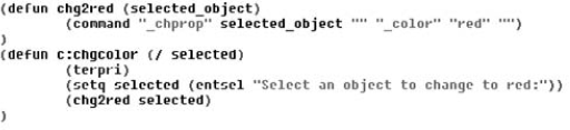
This routine defines a function,
chg2red, which is not preceded byc:. It has one argument,selected_object.What AutoLISP actually ran when you typed chgcolor in Step 7 is the function
c:chgcoloron the fourth line of the routine. In the last AutoLISP statement in that function —(chg2red selected)— the variableselectedis derived from the previous step as a result of the operationentsel(entity select).The variable
selectedis the argument passed to the functionchg2red. The functionchg2rednow knows what object to operate on.The function
chg2redthen uses the CHPROP command to change the object's color to red.
Note
To call a function at the command line, you would need to type (func arg) where func is the name of the function defined in a loaded AutoLISP routine (in this case, it is chg2red) and arg is an argument (in this case, it must be an entity name). Entity names are discussed later in this chapter.
AutoCAD has a wide variety of system variables to control the drawing environment. Thankfully, the creators of AutoLISP enabled the AutoLISP programmer to automate setting and retrieving AutoCAD system variables.
Don't confuse the terms variable and system variable. A variable is a value that is stored for use in a routine. A system variable is an AutoCAD setting that changes how AutoCAD works.
To set or retrieve AutoCAD system variables, you use two functions, SETVAR and GETVAR, which can be used on AutoCAD system variables. (You can use SETVAR only on system variables that are not read-only.) Here's how they work:
SETVAR stands for set variable. You use SETVAR to change a system variable. Place the system variable in quotes, followed by the new value, as in
(setvar "cmdecho" 0).GETVAR stands for get variable. It enables you to obtain the value of any system variable. As soon as you have the value, you can set it to a variable. This is often done so that you can return a system variable to its previous value if you've changed it during a routine. Place the system variable in quotes, as in
(getvar "cmdecho").
Although you can use SETVAR and GETVAR on many system variables, here are two system variables that are often changed in an AutoLISP routine:
In all the AutoLISP routines created thus far, AutoCAD's command responses could be seen scrolling off the command-line window. The CMDECHO system variable determines whether you see prompts and input during the functioning of AutoLISP's COMMAND function. By default, echoing is on (set to 1). If you set it to 0, you do not see prompts and input, and the functioning of the AutoLISP routine looks cleaner and runs slightly faster.
The FILEDIA system variable turns on and off the display of dialog boxes that enable you to choose files. Turning off this system variable enables you to work with files on the command line in AutoLISP routines.
Note
The file used in the following exercise on using AutoLISP to work with system variables, ab35-a.lsp, is in the Drawings folder on the DVD.
STEPS: Using AutoLISP to Work with System Variables
If you did the previous exercise and copied
ab35-a.lspto AutoCAD'sSupportfolder (or another folder that you created for AutoLISP routines, and added to AutoCAD'ssupport-file search path), open it from that folder. If you did not do the previous exercise, copyab35-a.lspfrom the DVD to AutoCAD'sSupportfolder, or another folder in AutoCAD's support-file search path.Start a new drawing by using the
acad.dwttemplate. Choose Manage tab(defun chg2red (selected_object) (command "_chprop" selected_object "" "_color" "red" "") ) (defun c:chgcolor (/ selected old_cmdecho) (setq old_cmdecho (getvar "cmdecho")) (setvar "cmdecho" 0) (terpri) (setq selected (entsel "Select an object to change to red:")) (chg2red selected) (setvar "cmdecho" old_cmdecho) )
Save the file as
ab35-01.lspin the same location.Choose Load Active Edit Window to load the routine.
Draw any object.
At the command line, type chgcolor
At the
Select an object to change to red:prompt, select the object that you drew in Step 5. You no longer see the prompts scrolling by. The object that you select turns red, and AutoCAD immediately displays the command prompt.
Don't save your drawing.
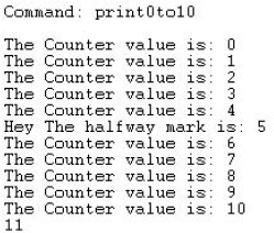
Here's how this routine works. This discussion assumes that you have already read the discussion of the previous routine, which was very similar.
First, you added a new variable,
old_cmdecho, to thechgcolorfunction.In the following line, you set this variable to the current value of the CMDECHO system variable. You obtained this current value by using GETVAR.
You then used SETVAR to set the AutoCAD system variable CMDECHO to 0.
You may need to see the commands echoed for debugging purposes, so it would prove best to return CMDECHO to the value that it was set to before running the routine. Therefore, in the last line, you use SETVAR again to reset CMDECHO to the variable
old_cmdecho, which stored the original value of CMDECHO.
As a result of these changes, the chgcolor program always sets the CMDECHO system variable back to the value it had before being run.
Lists are the primary structures that you work with while programming in AutoLISP. As you work in this chapter, you'll begin to understand the use of lists to modify objects (also called entities) in the AutoCAD database, and in a variety of other contexts with AutoLISP. AutoCAD represents all object data in a list that contains many smaller lists, but the lists are simple to use and manipulate.
A list is always enclosed in parentheses with spaces between the elements of the list. One common use for lists is for coordinates, as shown in the following example:
(1.0 3.5 2.0)
This list represents the X,Y,Z coordinates 1.0,3.5,2.0. You often need to extract one or more of the elements in a list. Table 35.1 shows the common list-extraction functions, using the example list (1.0 3.5 2.0).
Table 35.1. Basic List-Extraction Functions
Function | Pronunciation | Example Output | Description |
|---|---|---|---|
CAR | Car |
| Returns the first element in a list |
CDR | Could-er |
| Removes the first element from a list |
CADR | cad-er |
| Returns the second element in a list |
CADDR | ca-did-der |
| Returns the third element in a list |
For more flexibility, you can use the NTH function. Use the NTH function to access any element in a list by passing two arguments that specify the number of the element (items are numbered starting from 0) and the list that you want.
The name of the list is usually a variable set with SETQ:
(setq corner (list 1.0 3.5 2.0))
In this example, (nth 0 corner) returns 1.0 because 1.0 is the first item in the list corner.
The LIST function creates a list. If all the items in a list are constant values (not variables), you can use the QUOTE function to create a list. You can use a single quote (the same as an apostrophe on the keyboard) as a shortcut for the QUOTE function. The following two functions are equivalent:
(setq corner (list 1.0 3.5 2.0))
(setq corner '(1.0 3.5 2.0))
Many more AutoLISP list-extraction functions are detailed in the AutoLISP Function Synopsis Appendix of the AutoLISP Developer's Guide. Look under Basic Functions; then List Manipulation Functions. However, you can go a long way by remembering the functions listed here.
A dotted pair is a special type of list that contains only two elements. Some AutoLISP functions do not accept dotted pairs as an argument, but they're used to represent AutoCAD database objects. To construct a dotted pair, use the CONS function:
(cons 40 4.5)
This example returns (40 . 4.5). This list type is known as a dotted pair because it contains exactly two elements, and the elements are separated by a period or dot.
STEPS: Working with AutoLISP Lists
Start a new drawing by using the
acad.dwttemplate.Choose Manage tab
In the Visual LISP Console window, type (setq endpt '(3.5 2.0 1.4))
Continue in the Visual LISP Console. Type (car endpt)
Type (cadr endpt)
Type (cdr endpt)
Type (nth 1 endpt)
Don't save your drawing.
Often, you want to execute a procedure based on a certain condition. One way of doing this is with the IF statement, which does one thing if a statement is true and another thing if it's false. In other words, the operation is conditioned on the truth of a certain statement.
Looping is an important part of programming. Frequently, you want to execute a procedure over and over until the routine has finished operating on all the target objects or items. Looping sets up the condition that determines when the operation starts, the number of objects upon which the routine operates, and when the operation ends.
Conditional statements enable program flow to be determined, based on the outcome of a given decision. These decisions result in the return of either T, meaning true, or nil, meaning false. To try out the following statements, type them in the Visual LISP Console window. For instance, for the statement
(< 3 5)
T
AutoLISP returns T for true, having determined that 3 is less than 5. For the statement
(> 3 5)
nil
AutoLISP returns nil for false, having determined that 3 is not greater than 5. For the statement
(= 3 5)
nil
AutoLISP returns nil, because 3 is not equal to 5. Because conditional statements return either T or nil, you can use the IF statement. The general syntax of the IF statement is (if conditional-test if-true if-false). You can also use the IF statement with other functions that return a value; nil is always evaluated as the if-false potion of the IF statement while T or any other value is evaluated as the if-true portion.
For example, you may want to find circles whose radius is less than 0.25. In this case, you could use the following IF statement. In this example, radius is a variable that has been previously set.
(if (< radius 0.25)
  (princ  "
The radius is less than .25")
  (princ  "
The radius is not less than .25")
 )
The conditional test is (< radius 0.25). The if-true statement is (princ "
The radius is less than .25"). The if-false statement is (princ "
The radius is not less than .25"). This IF statement is equivalent to saying, "If the radius is less than .25, print 'The radius is less than .25' but if not, print 'The radius is not less than .25.'"
You can leave out the if-false statement. In this case, AutoLISP executes the if-true statement if the conditional statement is true and does nothing if it's false, and continues on to the rest of the program. In the following exercise, you see both types of IF statements, one nested inside the other.
STEPS: Using the IF Statement
Start a new drawing in AutoCAD by using the
acad.dwttemplate.Open Visual LISP, start a new file, and type the following:
(defun c:compare2three (/ entered_num)(setq entered_num (getint " Enter an integer: "))(if (< entered_num 3)(princ " The entered number is less than 3.")(if (= entered_num 3)(princ " The entered number is equal to 3.")(princ " The entered number is greater than 3.")))(princ))The GETINT function gets an integer from the user and is covered later in this chapter. The PRINC function prints a text string on the command line. The
Enter an integer:prompt starts a new line; it's similar to using(terpri). Using(princ)at the end of a routine is also covered later in this chapter.Choose Check Edit Window. If you see any error message in the Build Output window, check your typing, make any necessary corrections, and try again.
Save the file as
ab35-02.lspin a folder that is in the support-file search path, or inAutoCAD 2010Support.Choose Load Active Edit Window and then choose Activate AutoCAD.
To try out the IF statement, type compare2three
Repeat the COMPARE2THREE command. At the
Enter an integer:prompt, type 3Repeat the COMPARE2THREE command. At the
Enter an integer:prompt, type 2
Don't save your drawing.
Looping provides the capability to execute a step or a number of steps a given number of times, based on an evaluation that you make in your application. One way to do this is with the WHILE function.
The format of the WHILE function is:
(while conditional-test-if-true
        then-perform-following-code-until-condition-is-false)
One method that can be useful with a WHILE conditional-test-if-true statement is to include a counter for the WHILE expression. A counter counts how many times an operation is executed. You can then end the operation when the counter reaches a certain number. To create a counter, set a variable (perhaps named "counter") to the number at which you want to start. Then write the code for one pass through the looping statement. Then set the counter to the next higher number, using an expression, such as the following:
(setq counter (+ 1 counter))
The routine then loops back over the statements until the counter reaches the value that you set.
Here's a simple example:
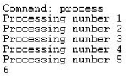
(defun c:process (/ counter)
  (setq counter 1)
  (while (< counter 6)
    (princ "
Processing number ")
    (princ counter)
    (terpri)
    (setq counter (+ 1 counter))
  )
)
In this example, the process function starts by setting the variable counter to 1. Then you start the WHILE statement and specify that the counter must be less than 6. Within the WHILE statement, you print the text string "Processing number" and then the value of the counter variable. You use (terpri) so that each text string starts on a new line. Then you set the counter to the next higher number. Each time through the WHILE loop, the value of the counter is incremented by 1. Without the increment statement, line 3 would always evaluate to true, and the WHILE loop would never exit because the counter would always be 1.
If you accidentally program an infinite loop like this, you can stop the execution of your AutoLISP routine by pressing Esc, pressing Ctrl+Break, or choosing Debug
In the preceding example, the WHILE loop continues as long as the counter is less than 6. When the counter reaches 6, the WHILE function stops. The WHILE statement returns the last value of the routine, so AutoCAD prints 6 on the last line. Figure 35.2 shows the result.
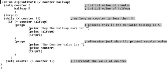
When using WHILE, you may want to combine several operations under the condition. The IF function normally evaluates one then expression if the test expression is true. Suppose you want an IF expression that processes various tasks if the test condition is true. An IF expression, as previously mentioned, processes a "do-if-true" and "do-if-false." Therefore, to process more than one "do-if-true" expression, you need to separate the "do-if-true" processes from the "do-if-false" processes. To accomplish this, use PROGN (short for program nest) to include (or nest) all items that you want executed when the test is true. In general, PROGN evaluates all the statements within its parentheses and returns the last evaluation as if it were one statement, as the following example demonstrates.
In the following example, you see the same IF statements used in an earlier example. However, after the second IF statement, you want your routine to print two lines if the entered number equals 3. You can do this by enclosing the two lines of code (plus a terpri) within a PROGN statement:
(defun c:compare2three (/ entered_num)
  (setq entered_num (getint "
Enter an integer: "))
  (if (< entered_num 3)
    (princ "
The entered number is less than 3.")
    (if (= entered_num 3)
      (progn
        (princ "
The entered number is equal to 3.")
        (terpri)
        (princ "
This is the one we are looking for.")
      )
      (princ "
The entered number is greater than 3.")
    )
  )
  (princ)
)
Note
The file used in the following exercise on using WHILE, IF, PROGN, and a counter, ab35-b.lsp, is in the Drawings folder on the DVD.
STEPS: Using WHILE, IF, PROGN, and a Counter
Start a new drawing in AutoCAD with any template.
Open Visual LISP.
Click Open File on the Visual LISP Standard toolbar, and open
ab35-b.lspfrom the DVD.Save the file as
ab35-03.lspinAutoCAD 2010Supportor any folder in thesupport-file search paths. Figure 35.3 shows this routine.Load
ab35-03.lsp. Return to AutoCAD.Type print0to10
Don't save your drawing.
The real power of AutoLISP is in manipulating drawing objects. This section reveals how many of the AutoLISP routines perform their magic. You can find information about an object and then use that information to change the object. You can also create selection sets of objects.
Every object in the AutoCAD database has an entity name. This name enables you to reference that object anywhere in your AutoLISP application. To see an example of an entity name, type the following after starting a new drawing:
(command "_line" "3,3" "5,5" "")(entlast)
AutoLISP responds with an Entity name such as <Entity name: 2ed0520>.
The numbers will probably differ on your system, but using the information returned from ENTLAST enables you to programmatically get or set a variety of options on any given database object by referencing its entity name.
The ENTGET (entity get) function is the key to making modifications to the drawing database. The ENTGET function takes an entity name as an argument. After drawing the line in the preceding steps, type the following:
(setq myline (entget (entlast)))AutoLISP responds with:
((-1 . <Entity name: 15ac558>) (0 . "LINE") (330 . <Entity name:
   15ac4f8>)(5 . "2B") (100 . "AcDbEntity") (67 . 0)
(410 . "Model") (8 . "0")(100 . "AcDbLine") (10 3.0 3.0 0.0) (11 5.0
   5.0 0.0) (210 0.0 0.0 1.0))
This is a representation of how the line is stored in the AutoCAD drawing database. AutoLISP returns a large list that contains multiple smaller lists. Each of the smaller lists is referred to as a group indexed by the first element. The entity name is in group −1. Each of the initial numbers in the small lists represents a different quality of the line. These numbers are called object group codes. The object group codes used most often are listed in Table 35.2.
Table 35.2. Commonly Used AutoCAD Object Group Codes
Group Code | Description |
|---|---|
−1 | Entity name |
0 | Entity type |
1 | Text value |
8 | Layer |
10 | Start point (or center) |
11 | Endpoint (or alignment point) |
38 | Elevation |
39 | Thickness |
40 | Radius (or height of text) |
62 | Color |
67 | Paper space flag |
Note
As you can see from the 10, 11, and 40 codes, the meaning of the group codes can change, depending on the type of object that it's used for.
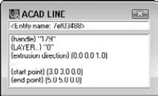
You can also use Visual LISP to examine an AutoCAD object. Begin by choosing View
After you end object selection, you're returned to Visual LISP, where you see the Inspect dialog box. Select the name of the entity and right-click while the cursor is over the selected text. Choose Inspect to see information about the object. Figure 35.5 shows information about an arc.
Not all these group codes are present in the line that you drew. For instance, group 62 (color) is absent in the list returned by AutoLISP. Every time you draw a line, you don't explicitly set its color. As a result, it defaults to the current color. In the same way, AutoLISP doesn't explicitly set every attribute of every group. In this case, the color is ByLayer and the current layer is 0. AutoLISP returned (8 . "0") in the preceding list to signify that the line is on layer 0.
There are many other group codes than the ones listed in Table 35.2, and they can be found in the Visual LISP Help system. From Visual LISP, choose Help
To manipulate a given attribute of an object, two important functions are ASSOC and SUBST:
ASSOC returns a list that finds the entry associated with an item in a list. It takes two arguments: the item in the list and the list itself. For example, if you specify the group code (such as 10) as the first argument, it returns the code's value (which would be the start point of a line). Or, if a list named
myobjectcontains three groups, as in((0 . "group 0") (1 1.0 2.0) (3 4.2 1.5 6.75)), then(assoc 1 myobject)would return(1 1.0 2.0).SUBST substitutes a value for every occurrence in a list. The SUBST function takes three arguments. To make the substitution, the first argument specifies what to substitute with, the second argument specifies what to substitute for, and the third argument specifies on what list to perform this operation.
To manipulate the start point of your line, first get the start point:
(setq startpt (assoc 10 myline))
AutoLISP responds:
(10 3.0 3.0 0.0)
To modify the start point of your line, use:
(setq new_startpt '(10 6.5 1.0 0.0))
(setq myline (subst new_startpt startpt myline))
AutoLISP responds:
((−1 . <Entity name: 15ac558>) (0 . "LINE") (330 . <Entity name:
   15ac4f8>)(5 . "2B") (100 . "AcDbEntity") (67 . 0)
(410 . "Model") (8 . "0")(100 . "AcDbLine") (10 6.5 1.0 0.0) (11 5.0
   5.0 0.0) (210 0.0 0.0 1.0))
In this case, new_startpt is substituted for the existing startpt in the object myline. No changes to the line are yet apparent. To commit the change, you need the ENTMOD function.
The key to modifying objects is the ENTMOD (entity modify) function. The list returned by AutoLISP can be modified and then passed to ENTMOD as an argument to update the AutoCAD database. Continuing with the previous example, if you enter:
(entmod myline)
AutoLISP responds:
((−1 . <Entity name: 15ac558>) (0 . "LINE") (330 . <Entity name:
   15ac4f8>) (5 ."2B") (100 . "AcDbEntity") (67 . 0)
(410 . "Model") (8 . "0") (100."AcDbLine") (10 6.5 1.0 0.0)
(11 5.0 5.0 0.0) (210 0.0 0.0 1.0))
The AutoCAD database is changed as well, and the start point of your line is now at X = 6.5, Y = 1.0, Z = 0.0.
A selection set is created with the SSGET (selection set get) function. This prompts the user with the familiar Select objects: prompt. Table 35.3 shows commonly used selection-set functions.
Table 35.3. Common AutoCAD Selection-Set Functions
Function | Description |
|---|---|
SSGET | Obtains a selection set from the user. |
SSLENGTH | Returns the number of objects in a selection set. It takes one argument, which is the selection set. |
SSNAME | Returns the entity name of a given object in a selection set. It takes two arguments: the selection set and the number of the object in the selection set. The first item number is 0, the second is 1, and so on. |
You can use a maximum of 128 selection sets at any given time. To release a selection set back to AutoLISP so that it can be used again, set the selection set to nil, as in (setq ss nil).
For example, you can enter the following in a new drawing:
(command "_circle" "3,3" "2") nil (command "_circle" "4,4" "3") nil (command "_line" "7,2" "6,6" "3,4" "5,5" "") nil (setq mysset (ssget)) Select objects:all5 found Select objects:<Selection set 1>
Now mysset is set to the selection set specified by all, which includes the three line segments and the two circles. To see what you have in your selection set, type the following, either on the command line or in the Visual LISP Console window:
(sslength mysset)5
You now know that you have five objects in your selection set. The first object is number 0, and the fifth object is number 4. To see what the first object is, enter the following:
(ssname mysset 0)<Entity name: 3fe0550>
To get the database data on the object, enter:
(entget (ssname mysset 0))Visual LISP responds:
((−1 . <Entity name: 3fe0550>) (0 . "LINE") (330 . <Entity name:
  16014f8>)(5 . "30") (100 . "AcDbEntity") (67 . 0) (410 . "Model") (8 . "0")(100 . "AcDbLine") (10 3.0 4.0 0.0) (11 5.0 5.0 0.0) (210 0.0 0.0 1.0))
By stepping through each of the entity names returned by SSNAME from 0 to 4, you can manipulate each of the objects in the selection set.
STEPS: Creating Selection Sets
Start a new drawing by using the
acad.dwttemplate, and type the following in a new file in the Visual LISP edit window. Save it asab35-04.lspin yourAutoCAD 2010Supportfolder or any folder in the support-file search path.(defun c:listsset (/ mysset counter) (setq mysset (ssget)) (setq counter 0) (while (< counter (sslength mysset)) (terpri) (princ (cdr (assoc 0 (entget (ssname mysset counter))))) (setq counter (+ counter 1)) ) (princ) )Load
ab35-04.lsp.Activate AutoCAD and draw any number of objects on-screen — at least two different types of objects.
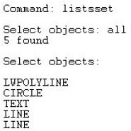
Type listsset
Select all the objects in your drawing. The routine prints the type of each object that you selected. (Press F2 to open the AutoCAD Text Window to see the entire results.) Figure 35.6 shows the results. Of course, your results will be different because you probably drew different types of objects.
Here's a breakdown of the routine in Step 1:
Line 1 creates a function and declares two variables,
myssetandcounter.Line 2 sets the
myssetvariable equal to the selection set that the user provides by using SSGET.Line 3 sets the
countervariable to 0, because selection sets work on a zero-based index (the first item is 0).Line 4 starts a WHILE loop. Working from the innermost set of parentheses, you first obtain the number of objects in the
myssetselection set, using SSLENGTH. Then you specify that the WHILE loop will continue as long as the counter is less than the number of objects in themyssetselection set. In other words, when the routine has cycled through all the objects in the selection set, it stops.Line 5 uses TERPRI to start a new line before printing out the object type of the selected object.
Line 6 prints the object type of the selected object. Working from the innermost set of parentheses, the routine first obtains the name of the object in the
myssetselection set whose number is equal to the variablecounter. The routine then gets that object by using ENTGET. The routine then gets the name of that object by using ASSOC with the 0 group code. The result is a dotted-pair list whose second item is the name of the object. The CDR function eliminates the first item in the dotted-pair list, leaving just the name of the object, which is what you want. The routine then prints the result.Line 7 sets the counter up one to repeat the WHILE loop for the next object.
Line 8 closes the WHILE loop.
Line 9 exits the routine quietly. (I discuss exiting quietly later in the chapter.)
Line 10 closes the entire function.
The course of your AutoLISP routines may often depend on user input. To satisfy this need, AutoCAD has a family of functions prefaced with the word GET. You have seen requests for user input while using commands; LINE or CIRCLE, for example, request input in the forms of points or distances. You have seen GETVAR for obtaining system variable information. Table 35.4 shows some other useful GET functions.
Table 35.4. Basic User-Input Functions
Function | Description |
|---|---|
GETDIST | Returns the distance between two points |
GETINT | Returns an integer |
GETREAL | Returns a real number (which can be a non-integer, negative, and so on) |
GETSTRING | Returns a text string |
Within the COMMAND function, you can use the PAUSE variable to pause and enable user input, such as picking a point or typing a value. For example, the expression (command "circle" pause "3") pauses to let the user specify a center point and then creates a circle with a radius of 3.
Notice the function ENTSEL in the next exercise. This is a type of shorthand for SSGET. Use it when you want to limit the user to selecting a single object. ENTSEL returns an entity name and the coordinates of your pick point in a dotted-pair list. Therefore, you can use CAR before ENTSEL to get the entity name for ENTGET.
There is also a new argument for GETSTRING, T. If you use this argument and it isn't nil, users can place spaces in the input. Using this argument enables users to type a text value that includes more than one word. Without the T, AutoLISP would interpret a space as equivalent to pressing Enter.
STEPS: Getting User Input
Start a new drawing by using the
acad.dwttemplate.Start Visual LISP, open a new file, and enter the following routine. Save it as
ab35-05.lspinAutoCAD 2010Supportor a folder that you've added to the support-file search path.(defun c:chgmytext (/ src_object new_ht new_str) (setq src_object (entget (car (entsel)))) (setq new_ht (getreal " What is the new height? ")) (setq new_str (getstring T " What is the new text value? ")) (setq src_object (subst (cons 40 new_ht) (assoc 40 src_object ) src_object) ) (setq src_object (subst (cons 1 new_str) (assoc 1 src_object) src_object) ) (entmod src_object) (princ) )Choose Format Edit Window from the Visual LISP Tools toolbar.
Load
ab35-05.lsp.Create some text by using either the DTEXT or the TEXT command and run
chgmytexton it. AutoCAD changes the text object's height and content to the values that you input in response to the prompts.
Don't save your drawing.
Here's a breakdown of the routine in Step 2:
Line 1 defines the function and declares three local variables.
Line 2 uses ENTSEL to let the user select one object. As explained earlier, CAR enables you to get just the entity name. ENTGET gets this entity name so that you can modify it. Finally, this line sets the resulting entity data equal to the variable
src_object.Line 3 prompts the user for a new height for the text and sets the entered number equal to the
new_htvariable.Line 4 prompts the user for a new text value (a new string) and sets the entered text value equal to the
new_strvariable.Line 5 starts the process of substituting the new values for the old values. Here the routine starts to set the new value for
src_object.Line 6 uses SUBST to substitute the new text height for the old text height for the object
src_object. (Group code 40 represents text height.)Line 7 closes the SETQ function.
Line 8 is the same as line 5. You'll be repeating the process of lines 5 through 7 for the new text (string) value.
Line 9 uses SUBST to substitute the new text value for the old text value. (Group code 1 represents the text value.)
Line 10 closes the SETQ function.
Line 11 uses ENTMOD on
src_objectto make the change in the drawing database.Line 12 exits quietly.
Line 13 closes the entire function.
You have a number of finishing touches that you should add to a routine before you can call it complete. All AutoLISP expressions return a value, and the last expression returns its value on the command line. You've noticed the PRINC function at the end of several routines. PRINC returns a blank line and, therefore, ensures that no extraneous evaluation return values are echoed on the command line. Using the PRINC function in this way is called exiting cleanly or exiting quietly.
Most of the AutoLISP applications covered thus far do not include much in the way of error handling. A new function called EQUAL is used on line 5 of the final routine in the next exercise. EQUAL is different than = in that EQUAL returns true only if two expressions are equal (each of the two objects tested for equality are evaluated before checking whether they're equal). A simple rule of thumb is to use EQUAL for list comparisons and = for numeric and string comparisons.
In the routine in the next exercise, if you select an object that is not a text object, the program jumps to line 20 and prints the error message You must select a text object.
A similar type of error handling is to enclose the selection of objects in an IF function. The IF function's test condition has to exist in order for the IF function to work. Therefore, if your user doesn't select an object, the test evaluates as false. You can place an error message as the if-false part of the IF function to catch this type of error.
This type of error handling is crucial to making your AutoLISP programs look finished and function properly.
Another way to finish off your routine is to add comments. Start with a comment at the beginning that states the purpose and function of the routine. This helps others understand what the routine does and can help you as well when you look at the routine again a few months later! Comments are prefaced with a semicolon.
Continue to make comments throughout your code. A lack of comments can make even the most useful code useless. Most professional programmers fully comment and document a function's purpose and behavior by placing comments within the code.
Visual LISP supports several commenting styles. When you click Format Edit Window on the Tools toolbar, Visual LISP uses these styles to automatically format your code. Here's how they work:
;;; Triple semicolon. When you type a comment with three semicolons, Visual LISP places the comment at the left margin. You can use a triple semicolon comment at the beginning of your routine to describe its overall purpose and what it does.
;; Double semicolon. Visual LISP indents a comment with two semicolons at the current nesting level, flush with the next level of parentheses. You can use this type of comment to explain the next line or lines of code.
; Single semicolon. By default, Visual LISP indents a comment with one semicolon by 40 spaces. Choose Tools
;| |; Inline comment. Place an inline comment within any line of code so that it has code both before and after it. An inline comment is formatted as follows:
;|This is a comment|;. You use the pipe symbol (usually over the backslash) along with the semicolon. You can use an inline comment to explain a small section of code within a line, or to span comments over several lines without adding a semicolon before each line.;_ End-of-line comment. Place an end-of-line comment at the end of any line of code. An end-of-line comment is formatted as follows:
;_ This is an end-of-line comment. You use the underscore symbol along with the semicolon. You can use an end-of-line comment to explain which function is matched to which closing parenthesis. This is especially useful for conditional functions where one closing parenthesis can be several lines from the opening parenthesis.
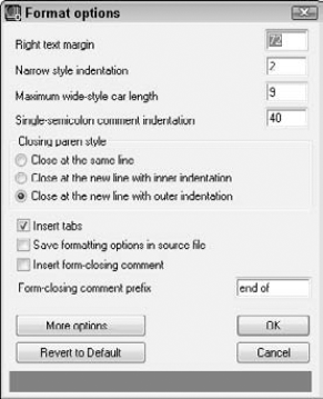
Figure 35.7. Use the Format Options dialog box to format margins and indentation in the Visual LISP editor.
STEPS: Putting on the Finishing Touches
Load the application that was completed in the previous exercise. If you didn't do the previous exercise, enter the text of the
chgmytextroutine from that exercise in Visual LISP's edit window, and save it asab35-05.lspinAutoCAD 2010Supportor in a folder that you've added to the support-file search path. Then load it with any drawing that you open in AutoCAD.Now run
chgmytextand choose an object that is not a text object (such as a circle) in response to theSelect object:prompt. Answer the prompts for new height and new text values.If the selected object is a circle, you see its radius change to match the value that you specified to be the new text height. This is definitely not what you intended when writing this program.
Modify the program so that it reads as follows, and save it as
ab35-06.lsp:;;;modifies text height and content (value) (defun c:chgmytext (/ src_object new_ht new_str) (terpri) (setq src_object (entget (car (entsel)))) (if (equal (assoc 0 src_object) '(0 . "TEXT")) (progn (prompt " What is the new height for the text? ") (setq new_ht (getreal)) (prompt " What is the new text value? ") (setq new_str (getstring)) (setq src_object (subst (cons 40 new_ht) (assoc 40 src_object) src_object) ) (setq src_object (subst (cons 1 new_str) (assoc 1 src_object)src_object) ) (entmod src_object) ) (princ" You must select a text object.") ) (princ) )Load
ab35-06.lsp. Startchgmytextand try out the routine again with a circle or other non-text object.
Don't save your drawing.
In this chapter, you learned:
How to create variables
How to create AutoLISP functions
How to work with AutoCAD commands and system variables
About extending AutoLISP's power by using lists and looping
How to modify and get information about drawing objects
How to create selection sets
About obtaining user input
Tools for finishing off your AutoLISP routines by adding some error handling, making sure that the routine exits quietly, and adding helpful comments about the routine's function
In the next chapter, you read about some of the more-advanced features of Visual LISP.