
Learning AutoCAD or AutoCAD LT is a bit like trying to decide which came first — the chicken or the egg. On one hand, you need to know the basics before you can start drawing. On the other hand, understanding the basics can be very difficult if you haven't had the experience of drawing something. In this Quick Start chapter, you resolve this problem by drawing, dimensioning, and printing a simple window in AutoCAD or AutoCAD LT.
This Quick Start chapter is meant for beginners. You get the feel of AutoCAD's precision drawing tools and experience how to build a drawing. The AutoCAD/AutoCAD LT interface is very customizable. Note that the instructions for the exercise in this chapter assume that no one has made major changes to the default settings.
Chapters 1-5 fill you in on basic information that you need to move on to drawings that are more complex. By experiencing the drawing process first, you will find the initial learning curve to be easier and smoother.
Note
Don't worry if you don't immediately understand everything you're doing. It all becomes clear as you progress through this book. If you haven't read the Preface, now is a good time to go back and read the part that explains how to follow the exercises. When you type the X and Y coordinates (shown in bold), type the first number, a comma, and then the second number, with no spaces between them. The
Note
When you start AutoCAD 2010 for the very first time, the Initial Setup dialog box appears, asking you to answer a series of questions. It is simply a method for you to create a custom workspace according to your industry and user interface preferences. You can skip this part by clicking Skip, and run it later.
You see the new drawing. (If you are prompted for a template, skip to Step 2, third sentence.)
Choose Application Button

Note
You need to open this template for the rest of the exercise to work properly.
To save the drawing and give it a name, choose Application Button
Note
In Chapter 1, I provide instructions for creating a special
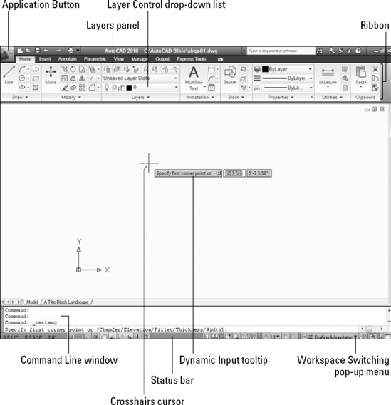
AutoCAD Biblefolder for all the exercises in this book. If you want to create this folder now, do so and save the drawing in that folder.To free up the drawing area, close any windows or palettes that are open by clicking their Close (X) button, so that your screen looks like Figure QS.1.
Note
This chapter assumes that you're using the default 2D Drafting & Annotation Workspace. Click the Workspace Switching button on the right side of the status bar at the bottom of your screen, and choose 2D Drafting & Annotation if it's not already checked.
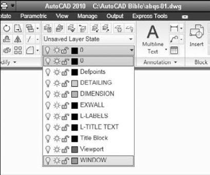
At the top of the screen, you see a tabbed area filled with buttons, called the Ribbon, which contains the Layers panel (section) on the Home tab, as shown in Figure QS.1. From the Layer Control drop-down list in the Layers panel, click the down arrow and choose WINDOW, as shown in Figure QS.2. (Layers help you organize the objects in your drawing; I cover them in detail in Chapter 11.) Anything you draw will now be on the WINDOW layer.


Follow these prompts to draw a rectangle that is 44″ wide and 80″ high.
Specify first corner point or [Chamfer/Elevation/Fillet/Thickness/Width]:
0,0Specify other corner point or [Area/Dimensions/Rotation]:
44,80Note
You see the full prompt shown here in the Command window at the bottom of your screen. You see an abbreviated version of the same prompt in the Dynamic Input tooltip that appears near the mouse cursor. In an architectural drawing, distances are assumed to be in inches, so you don't need to specify a unit (although you can if you want).
Notice that the text that you type appears next to the cursor in the Dynamic Input tooltip. When you press Enter, the text that you typed is echoed in the Command Line window at the bottom of the screen.

Specify offset distance or [Through/Erase/Layer] <Through>:
4Select object to offset or [Exit/Undo] <Exit>:Click the rectangle's border to select it. Specify point on side to offset or [Exit/Multiple/Undo] <Exit>:Click anywhere inside the rectangle. Select object to offset or [Exit/Undo] <Exit>:
Specify first point:
Press and hold the Shift key and right-click. From the shortcut menu that opens, choose Midpoint. Place the cursor near the midpoint of the left side of the inner rectangle. When you see a triangle and the Midpoint tooltip, click.Specify next point or [Undo]:
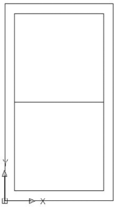
Press and hold the Shift key and right-click. From the shortcut menu that opens, choose Midpoint. This time, place the cursor near the midpoint of the right side of the inner rectangle. When you see the Midpoint tooltip and triangle, click. Specify next point or [Undo]:Your drawing should now look like Figure QS.3. (Your window should be green.)
Specify first point:
Press Shift and right-click. Choose Endpoint from the shortcut menu. Pick the left endpoint of the last line you drew. Specify next point or [Undo]:4,4.(This notation specifies that the endpoint of the line is 4 units above and to the right of the first point. Chapter 4 explains more about specifying coordinates in this manner.)Specify next point or [Undo]:
Specify first corner point or [Chamfer/Elevation/Fillet/Thickness/Width]:
Press Shift and right-click. Choose Endpoint and pick the final endpoint of the diagonal line you just drew. Specify other corner point or [Area/Dimensions/Rotation]:2′4″,2′4″Note
This notation specifies 2 feet, 4 inches in the X and Y directions.


Specify first point:
8″,3′4″Specify next point or [Undo]:Move the mouse cursor down from the start point of the line. You see a temporary drag line. Then type the following length of the line.2'8-7/16Tip
You can see what you type in the Dynamic Input tooltip as you are typing. Therefore, you can check that you've typed the right numbers before you press Enter.
Specify next point or [Undo]:
Move the cursor horizontally to the right and type28. Specify next point or [Close/Undo]:Now try entering the distance using decimal notation, rather than feet and inches. Move the cursor up and type32.4375Specify next point or [Close/Undo]:To draw shutters, first change the layer. Choose Home tab

Specify first point:
Press Shift and right-click. Choose Endpoint from the shortcut menu. Click the upper-left corner of the window. Specify next point or [Undo]:Move the cursor to the left. Type1′6″Specify next point or [Undo]:Move the cursor down. Type6′8″Specify next point or [Close/Undo]:Type#0,0.(The pound sign ensures that your line goes to 0,0 no matter where you are.)Specify next point or [Close/Undo]:
Select objects:
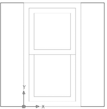
Click the three lines that make up the shutter. Select objects:Specify first point of mirror line:Press Shift and right-click. Choose Midpoint from the shortcut menu.Place the cursor near the middle of the top horizontal line of the window. Click when you see the triangle and Midpoint tooltip. Specify second point of mirror line:(The Ortho Mode button should still be blue. If it isn't, click it.) Move the cursor downward and pick any point. Erase source objects? [Yes/No] <N>:The window should look like Figure QS.4.
To add a dimension to the bottom of the window, you should first change the layer. Choose Home tab

Specify first extension line origin or <select object>:
(Pressing Enter lets you select an object to dimension.)Select object to dimension:Pick the bottom horizontal line of the window (the bottom of the rectangle). Specify dimension line location or [Mtext/Text/Angle/Horizontal/Vertical/Rotated]:Move the cursor down until the dimension is nicely spaced below the window. Click to place the dimension line.Note
If you don't have enough room to place the dimension below the window, click the down arrow of the vertical scroll bar as necessary. In Chapter 8, I explain additional techniques for changing the view of your drawing.

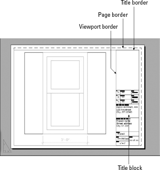
To prepare for printing, click the A Title Block-Landscape tab just above the Command line, on the left. (If you don't see a tab, click the A title Block-Landscape button, which is the second button from the left in the right-hand group of buttons on the status bar at the bottom of your screen.) You then see the window inside a titleblock and border, as shown in Figure QS.5. This titleblock and border come with the template to help you easily prepare the drawing for printing. (Chapter 17 explains how to lay out and print/plot a drawing.)


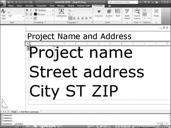
These words should now appear very large in the drawing area. They are already placed and formatted, so all you need to do is replace them. (I explain all about how to create and edit text in Chapter 13.)
Double-click the
Project nametext. A new Text Editor tab appears, along with a ruler, as shown in Figure QS.6.Select the text by dragging from the upper-left corner to the lower-right corner. Type the following:
Double-hung window
2010 Coral Lane
Anytown, IA 12345
Click the Close Text Editor button at the right end of the Text Editor tab to close the In-Place Text Editor.


In the Printer/Plotter section of the Plot dialog box, click the Name drop-down list and choose the printer or plotter that you want to use.
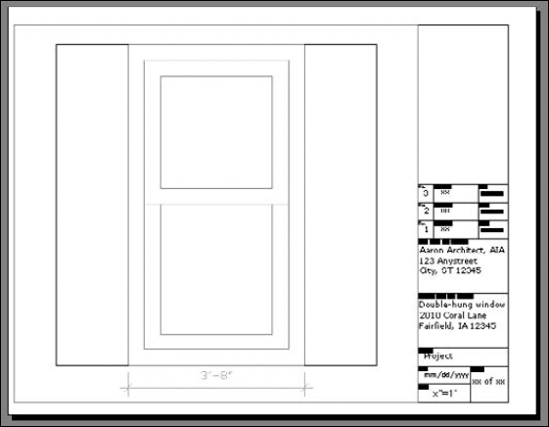
Click the Preview button to open the preview window. You should see the window and its titleblock laid out, as shown in Figure QS.7.
Note
If things don't seem right, click the Close Preview Window button and review the previous steps to see if you can find the problem. Also, see the sidebar, "Help! My drawing doesn't look like the figure."

Click the Close button at the upper-right corner of the AutoCAD application window to close both AutoCAD and the drawing. Click Yes to save your changes.
Note
It's important to understand that this Quick Start tutorial uses techniques that are easiest to understand for beginners; as a result, the techniques were sometimes a little awkward. AutoCAD and AutoCAD LT have many capabilities that make drawing easier and faster. You learn all these features in this book.
Help! My drawing doesn't look like the figure
If your drawing doesn't look like the image shown in Figure QS.7, there could be several reasons. To fix the problem, try one of the following solutions:
You may have made a mistake when creating the drawing. If you think that's the case, start over and follow the prompts again.
You may have started AutoCAD or AutoCAD LT based on a template with different properties from the default. Be sure to use the template on the AutoCAD 2010 and AutoCAD LT 2010 Bible DVD, as explained in Step 2 of the preceding exercise. Then follow the prompts again.
If your drawing still seems wrong, put the DVD that accompanies this book in your DVD drive. Choose Application Menu
One of the preceding options should solve your problem.
In this exercise, you practiced many of the skills that you need to use AutoCAD or AutoCAD LT effectively. Most of your work in AutoCAD or AutoCAD LT builds on these basic skills. The rest of the chapters in this book explain these procedures in more detail as well as many features not covered in this Quick Start exercise.