
Project 4 – Interactive Traffic Lights
This time you are going to extend the previous project to include a set of pedestrian lights and a pedestrian push button to request to cross the road. The Arduino will react when the button is pressed by changing the state of the lights to make the cars stop and allow the pedestrian to cross safely.
This is the first time you are going to interact with the Arduino and cause it to do something when you change the state of a button that the Arduino is watching. In this project, you will also learn how to create your own functions in code.
From now on, I will no longer list the breadboard and jumper wires in the parts required list. Note that you will always need these basic components.
Parts Required
2 Red Diffused LEDs ![]()
Yellow Diffused LED ![]()
2 Green Diffused LEDs ![]()
150 ohm Resistor ![]()
4 Resistors ![]()
Pushbutton ![]()
Choose the appropriate value resistor for the LEDs you are using in your project. The 150Ω resistor is for the pushbutton; it's known as a pull down resistor (which I will define later). The pushbutton is sometimes referred to by suppliers as a tactile switch and is ideal for breadboard use.
Connect It Up
Connect your circuit as shown in Figure 2-8. Double-check your wiring before providing any power to your Arduino. Remember to have your Arduino disconnected to the power while wiring up the circuit.

Figure 2-8. The circuit for Project 4 - Traffic light system with pedestrian crossing and request button (see insert for color version)
Enter the Code
Enter the code in Listing 2-4, verify, and upload it. When you run the program, it begins with the car traffic light on green to allow cars to pass and the pedestrian light on red.
When you press the button, the program checks that at least 5 seconds have gone by since the last time the lights changed (to allow traffic to get moving), and if so, passes code execution to the function you have created called changeLights(). In this function, the car lights go from green to amber to red, and then the pedestrian lights go green. After the period of time set in the variable crossTime (time enough to allow the pedestrians to cross), the green pedestrian light flash on and off as a warning to the pedestrians to hurry because the lights are about to change to red. Then the pedestrian light changes to red, the vehicle lights go from red to amber to green, and the traffic flow resumes.
Listing 2-4. Code for Project 4
// Project 4 - Interactive Traffic Lights


int carRed = 12; // assign the car lights
int carYellow = 11;

int carGreen = 10;

int pedRed = 9; // assign the pedestrian lights

int pedGreen = 8;

int button = 2; // button pin

int crossTime = 5000; // time alloyoud to cross

unsigned long changeTime; // time since button pressed


void setup() {
        pinMode(carRed, OUTPUT);

        pinMode(carYellow, OUTPUT);

        pinMode(carGreen, OUTPUT);

        pinMode(pedRed, OUTPUT);

        pinMode(pedGreen, OUTPUT);

        pinMode(button, INPUT); // button on pin 2

        // turn on the green light

        digitalWrite(carGreen, HIGH);

        digitalWrite(pedRed, HIGH);

}


void loop() {
        int state = digitalRead(button);

        /* check if button is pressed and it is over 5 seconds since last button press */

        if (state == HIGH && (millis() - changeTime) > 5000) {

                // Call the function to change the lights

                changeLights();

        }

}


void changeLights() {

        digitalWrite(carGreen, LOW); // green off

        digitalWrite(carYellow, HIGH); // yellow on

        delay(2000); // wait 2 seconds


        digitalWrite(carYellow, LOW); // yellow off

        digitalWrite(carRed, HIGH); // red on

        delay(1000); // wait 1 second till its safe


        digitalWrite(pedRed, LOW); // ped red off

        digitalWrite(pedGreen, HIGH); // ped green on

        delay(crossTime); // wait for preset time period
        // flash the ped green

        for (int x=0; x<10; x++) {

                digitalWrite(pedGreen, HIGH);

                delay(250);

                digitalWrite(pedGreen, LOW);

                delay(250);

        }

        // turn ped red on

        digitalWrite(pedRed, HIGH);

        delay(500);


        digitalWrite(carYellow, HIGH); // yellow on

        digitalWrite(carRed, LOW); // red off

        delay(1000);

        digitalWrite(carGreen, HIGH);

        digitalWrite(carYellow, LOW); // yellow off


        // record the time since last change of lights

        changeTime = millis();

        // then return to the main program loop

}
Project 4 – Code Overview
You will understand and recognize most of the code in this project from previous projects. I'll just point out the new keywords and concepts:
unsigned long changeTime;
Here is a new data type for a variable. Previously, you created integer data types, which can store a number between -32,768 and 32,767. This time you created a data type of long, which can store a number from -2,147,483,648 to 2,147,483,647. However, you have specified an unsigned long, which means the variable cannot store negative numbers, so the range is from 0 to 4,294,967,295. If you use an integer to store the length of time since the last change of lights, you would only get a maximum time of 32 seconds before the integer variable reached a number higher than it could store.
As a pedestrian crossing is unlikely to be used every 32 seconds, you don't want your program crashing due to your variable “overflowing” when it tries to store a number too high for the variable data type. So you use an unsigned long data type to get a huge length of time in between button presses:
4294967295 * 1ms = 4294967 seconds
4294967 seconds = 71582 minutes
71582 minutes - 1193 hours
1193 hours - 49 days
It's pretty inevitable that a pedestrian crossing button will be pressed at least once in 49 days, so you shouldn't have a problem with this data type.
So why isn't there just one data type that can store huge numbers all the time? Well, because variables take up space in memory; the larger the number, the more memory is used up for storing variables. On your home PC or laptop, you won't have to worry about it much at all, but on a small microcontroller like the Arduino's Atmega32, it's essential that you use only the smallest variable data type necessary for your purpose.
Table 2-2 lists the various data types you can use in your sketches.
| Data type | RAM | Number Range |
| void keyword | N/A | N/A |
| boolean | 1 byte | 0 to 1 (True or False) |
| byte | 1 byte | 0 to 255 |
| char | 1 byte | -128 to 127 |
| unsigned char | 1 byte | 0 to 255 |
| int | 2 byte | -32,768 to 32,767 |
| unsigned int | 2 byte | 0 to 65,535 |
| word | 2 byte | 0 to 65,535 |
| long | 4 byte | -2,147,483,648 to 2,147,483,647 |
| unsigned long | 4 byte | 0 to 4,294,967,295 |
| float | 4 byte | -3.4028235E+38 to 3.4028235E+38 |
| double | 4 byte | -3.4028235E+38 to 3.4028235E+38 |
| string | 1 byte + x | Arrays of chars |
| array | 1 byte + x | Collection of variables |
Each data type uses up a certain amount of memory: some variables use only 1 byte of memory and others use 4 or more (don't worry about what a byte is for now; I will discuss this later). Note that you can't copy data from one data type to another. In other words, if x was an int and y was a string, x = y would not work because the two data types are different.
The Atmega168 has 1Kb (1000 bytes) and the Atmega328 has 2Kb (2000 bytes) of SRAM; this is not a lot of memory. In large programs with lots of variables, you could easily run out of memory if you do not optimize your usage of the correct data types. As you have used int (which uses up 2 bytes and can store a number up to 32,767) to store the number of your pin, which will only go as high as 13 on your Arduino (and up to 54 on the Arduino Mega), you have used up more memory than was necessary. You could have saved memory by using the byte data type, which can store a number between 0 and 255—more than enough to store the number of an I/O pin.
Next you have
pinMode(button, INPUT);
which tells the Arduino that you want to use Digital Pin 2 (button = 2) as an INPUT. You are going to use Digital Pin 2 to listen for button presses so its mode needs to be set to input.
In the main program loop, you check the state of pin 2 with this statement:
int state = digitalRead(button);
This initializes an integer (yes, it's wasteful and you should use a boolean) called state and then sets the value of state to be the value of Digital Pin 2. The digitalRead statement reads the state of the pin within the parenthesis and returns it to the integer you have assigned it to. You can then check the value in state to see if the button has been pressed or not:
 if (state == HIGH && (millis() - changeTime) > 5000) {

    // Call the function to change the lights

    changeLights();

  }
The if statement is an example of a control structure and its purpose is to check if a certain condition has been met or not. If so, it executes the code within its code block. For example, if you wanted to turn an LED on if a variable called x rose above the value of 500, you could write the following:
if (x>500) {digitalWrite(ledPin, HIGH);
When you read a pin using the digitalRead command, the state of the pin will either be HIGH or LOW. So the if command in your sketch looks like this:
if (state == HIGH && (millis() - changeTime) > 5000)
What you are doing here is checking that two conditions have been met. The first is that the variable called state is high. If the button has been pressed, state will be high because you have already set it to be the value read in from Digital Pin 2. You are also checking that the value of millis()-changeTime is greater than 5000 (using the logical AND command &&). The millis() function is one built into the Arduino language, and it returns the number of milliseconds since the Arduino started to run the current program. Your changeTime variable will initially hold no value, but after the changeLights) function runs, you set it at the end of that function to the current millis() value.
By subtracting the value in the changeTime variable from the current millis() value, you can check if 5 seconds have passed since changeTime was last set. The calculation of millis()- changeTime is put inside its own set of parenthesis to ensure that you compare the value of state and the result of this calculation, and not the value of millis() on its own.
state == HIGH
and the calculation is an example of a Boolean Operator. In this case, it means AND. To see what this means, let's take a look at all of the Boolean Operators:
&& - Logical AND
|| - Logical OR
! - NOT
These are logic statements and can be used to test various conditions in if statements.
&& means true if both operands are true, so this if statement will run its code only if x is 5 and y is 10:
if (x==5 && y==10) {....
|| means true if either operand is true; for example, this if statement will run if x is 5 or if y is 10:
if (x==5 || y==10) {.....
The ! or NOT statement means true if the operand is false, so this if statement will run if x is false, i.e. equals zero:
if (!x) {.......
You can also nest conditions with parenthesis, for example:
if (x==5 && (y==10 || z==25)) {.......
In this case, the conditions within the parenthesis are processed separately and treated as a single condition and then compared with the second condition. So, if you draw a simple truth table (see Table 2-3) for this statement, you can see how it works.
Table 2-3. Truth table for the condition (x==5 && (y==10 || z==25))
| x | y | z | True/False? |
| 4 | 9 | 25 | FALSE |
| 5 | 10 | 24 | TRUE |
| 7 | 10 | 25 | FALSE |
| 5 | 10 | 25 | TRUE |
The command within the if statement is
changeLights();
and this is an example of a function call. A function is simply a separate code block that has been given a name. However, functions can be passed parameters and/or return data, too. In this case, you have not passed any data to the function nor have you had the function return any date. I will go into more detail later on about passing parameters and returning data from functions.
When changeLights() is called, the code execution jumps from the current line to the function, executes the code within that function, and then returns to the point in the code after where the function was called.
In this case, if the conditions in the if statement are met, then the program executes the code within the function and returns to the next line after changeLights() in the if statement.
The code within the function simply changes the vehicles lights to red, via amber, then turns on the green pedestrian light. After a period of time set by the variable crossTime, the light flashes a few time to warn the pedestrian that his time is about to run out, then the pedestrian light goes red and the vehicle light goes from red to green, via amber, thus returning to its normal state.
The main program loop simply checks continuously if the pedestrian button has been pressed or not, and, if it has and (&&) the time since the lights last changed is greater than 5 seconds, it calls the changeLights() function again.
In this program, there was no benefit from putting the code into its own function, apart from making the code look cleaner and to explain the concept of functions. It is only when a function is passed parameters and/or returns data that their true benefits come to light; you will take a look at that later when you use functions again.
Project 4 – Interactive Traffic Lights - Hardware Overview
The new piece of hardware introduced in Project 4 is the button, or tactile switch. As you can see by looking at the circuit, the button is not directly connected between the power line and the input pin; there is a resistor going between the button and the ground rail. This is what is known as a pull-down resistor and it is essential to ensure the button works properly. I will take a little diversion to explain pull-up and pull-down resistors.
Logic States
A logic circuit is one designed to give an output of either on or off, which are represented by the binary numbers 1 and 0. The off (or zero) state is a voltage near to zero volts at the output; a state of on (or 1) is represented by a higher level, closer to the supply voltage. The simplest representation of a logic circuit is a switch (see Figure 2-9).
Figure 2-9. The electronic symbol for a switch
When the switch is open, no current can flow through it and no voltage can be measured at the output. When you close the switch, the current can flow through it, thus a voltage can be measured at the output. The open state can be thought of as a 0 and the closed state as a 1 in a logic circuit.
In a logic circuit, if the expected voltage to represent the on (or 1) state is 5v, it's important that when the circuit outputs a 1 that the voltage is as close to 5v as possible. Similarly, when the output is a zero (or off), it is important that the voltage is as close to zero volts as possible. If you do not ensure that the states are close to the required voltages, that part of the circuit may be considered to be floating (it is neither in a high or low state). The floating state is also known as electrical noise, and noise in a digital circuit may be interpreted as random 1's and 0's.
This is where pull up or pull down resistors can be used to ensure the state is high or low. If you let that node in the circuit float, it may be interpreted as either a zero or a one, which is not desirable. It's better to force it towards a desired state.
Pull-Down Resistors

Figure 2-10. A pull-down resistor circuit
Figure 2-10 shows a schematic where a pull-down resistor being used. If the button is pressed, the electricity takes the path of least resistance and moves between the 5v and the input pin (there is a 100 ohm resistor on the input pin and a 10K ohm resistor on ground). However, when the button is not pressed, the input is connected to the 100K ohm resistor and is pulled towards ground. Without this pull to ground, the pin would not be connected to anything when the button was not depressed, thus it would float between zero and 5v. In this circuit, the input will always be pulled to ground, or zero volts, when the button is not pressed and it will be pulled towards 5v when the button is pressed. In other words, you have ensured that the pin is not floating between two values. Now look at Figure 2-11.
Pull-Up Resistors
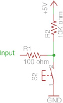
Figure 2-11. A pull-up resistor circuit
In this circuit, you have swapped the pull-down resistor and the switch. The resistor now becomes a pull-up resistor. As you can see, when the button is not pressed, the input pin is pulled towards the 5v, so it will always be high. When the button is pressed, the path of least resistance is towards the ground and so the pin is pulled to ground or the low state. Without the resistor between 5v and ground, it would be a short circuit, which would damage your circuit or power supply. Thanks to the resistor, it is no longer a short circuit as the resistor limits the amount of current. The pull-up resistor is used more commonly in digital circuits.
With the use of simple pull-up or pull-down resistors you can ensure that the state of an input pin is always either high or low, depending on your application.
In Project 4, you use a pull-down resistor to ensure a button press will register correctly by the Arduino. Let's take a look at the pull-down resistor in that circuit again (see Figure 2-12).
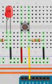
Figure 2-12. A pull-down resistor from Project 4 (see insert for color version)
This circuit contains a push button. One pin of the button is connected directly to 5v and the other is connected directly to Digital Pin 2. It is also connected directly to ground via a pull-down resistor. This means that when the button is not pushed, the pin is pulled to ground and therefore reads a zero or low state. When the button is pressed, 5 volts flows into the pin and it is read as a 1 or a high state. By detecting if the input is high or low, you can detect if the button is pressed or not. If the resistor was not present, the input pin wire would not be connected to anything and would be floating. The Arduino could read this as either a HIGH or a LOW state, which might result in it registering false button presses.
Pull-up resistors are often used in digital circuits to ensure an input is kept high. For example, the 74HC595 Shift Register IC (Integrated Circuit) that you will be using later on in the book has a Master Reset pin. This pin resets the chip when it is pulled low. As a result, it's essential that this pin is kept high at all times, unless you specifically want to do a reset; you can hold this pin high by using a pull-up resistor at all times. When you want to reset it, you pull it low using a digital output set to LOW; at all other times, it will remain high. Many other IC's have pins that must be kept high for most of the time and only pulled low for various functions to be activated.
The Arduino's Internal Pull-Up Resistors
Conveniently, the Arduino contains pull-up resistors that are connected to the pins (the analog pins have pull-up resistors also). These have a value of 20K ohms and need to be activated within software to use them. To activate an internal pull-up resistor on a pin, you first need to change the pinMode of the pin to an INPUT and then write a HIGH to that pin using a digitalWrite command:
pinMode(pin, INPUT);

digitalWrite(pin, HIGH);
If you change the pinMode from INPUT to OUTPUT after activating the internal pull-up resistors, the pin will remain in a HIGH state. This also works in reverse: an output pin that was in a HIGH state and is subsequently switched to an INPUT mode will have its internal pull-up resistors enabled.