Project 27 – Joystick Servo Control
For another simple project, let's use a joystick to control the two servos. You'll arrange the servos in such a way that you get a pan-tilt head, such as is used for CCTV cameras or for camera or sensor mounts on robots.
Parts Required
Leave the circuit as it was for the last project, and add either two potentiometers or a 2-axis potentiometer joystick.
| Standard RC Servo × 2 |  |
| 2-axis potentiometer joystick (or two potentiometers) |
Connect It Up
The circuit for Project 27 is the same as for Project 26, with the addition of the joystick.

Figure 9-6. The circuit for Project 27 – Joystick Servo Control (see insert for color version)
A potentiometer joystick is simply that: a joystick made up of two potentiometers at right angles to each other. The axles of the pots are connected to a lever that is swung back and forth by the stick and returned to their centre positions thanks to a set of springs.
Connection is therefore easy: the outer pins of the two pots going to +5v and Ground and the centre pins going to Analog Pins 3 and 4. If you don't have a joystick, two potentiometers arranged at 90 degrees to each other will suffice.
Connect the two servos so that one has its axle vertical and the other horizontal at 90 degrees to the first servo and attached to the first servo's armature sideways. See Figure 9-7 for how to connect the servos. Some hot glue will do for testing. Use stronger glue for a permanent fixing.
Alternatively, get one of the ready-made pan and tilt servo sets you can buy for robotics. These can be picked up cheaply on eBay.
When the bottom servo moves it causes the top servo to rotate, and when the top servo moves its arm rocks back and forth. You could attach a webcam or an ultrasonic sensor to the arm, for example.
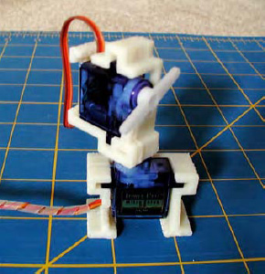
Figure 9-7. Mount one servo on top of the other (image by David Stokes)
The joystick can be purchased from eBay or an electrical supplier. You could also find an old C64 or Atari joystick. However, there is a cheap alternative available called a PS2 controller; it contains two 2-axis potentiometer joysticks as well as a set of vibration motors and other buttons. These can be purchased on eBay very cheaply and are easily taken apart to access the parts within (see Figure 9-8). If you don't want to take the controller apart, you could access the digital code coming from the cable of the PS2 controller. In fact, there are Arduino libraries to enable you to do just this. This will give you full access to all of the joysticks and buttons on the device at once.

Figure 9-8. All the great parts available inside a PS2 Controller (image by Mike Prevette)
Enter The Code
Enter the code in Listing 9-3.
Listing 9-3. Code for Project 27
// Project 27

#include <Servo.h>


Servo servo1;  // Create a servo object
Servo servo2;  // Create a second servo object

int pot1, pot2;


void setup()
{

  servo1.attach(5);  // Attaches the servo on pin 5 to the servo1 object

  servo2.attach(6);  // Attaches the servo on pin 6 to the servo2 object


  servo1.write(90);  // Put servo1 at home position

  servo2.write(90);  // Put servo2 at home postion


}


void loop()

{

  pot1 = analogRead(3); // Read the X-Axis

  pot2 = analogRead(4); // Read the Y-Axis

  pot1 = map(pot1,0,1023,0,180);

  pot2=map(pot2,0,1023,0,180);

  servo1.write(pot1);

  servo2.write(pot2);

  delay(15);

}
When you run this program you will be able to use the servos as a pan/tilt head. Rocking the joystick backwards and forwards will cause the top servo's armature to rock back and forth, and moving the joystick from side to side will cause the bottom servo to rotate.
If you find that the servos are going in the opposite direction from what you expected, then you have the outer pins of the appropriate servo connected the wrong way. Just swap them around.
Project 27 – Joystick Servo Control – Code Overview
Again, this is a very simple project, but the effect of the two servos moving is quite compelling.
The Servo library is loaded:
#include <Servo.h>
Two servo objects are created and two sets of integers hold the values read from the two potentiometers inside the joystick:
Servo servo1;  // Create a servo object

Servo servo2;  // Create a second servo object

int pot1, pot2;
The setup loop attaches the two servo objects to Pins 5 and 6 and moves the servos into the central positions:
servo1.attach(5);  // Attaches the servo on Pin 5 to the servo1 object

servo2.attach(6);  // Attaches the servo on Pin 6 to the servo2 object


servo1.write(90);  // Put servo1 at home position
servo2.write(90);  // Put servo2 at home postion
In the main loop, the analog values are read from both the X and Y axis of the joystick:
pot1 = analogRead(3); // Read the X-Axis

pot2 = analogRead(4); // Read the Y-Axis
Those values are then mapped to be between 0 and 180 degrees
pot1 = map(pot1,0,1023,0,180);

pot2 = map(pot2,0,1023,0,180);
and then sent to the two servos
servo1.write(pot1);

servo2.write(pot2);
The range of motion available with this pan/tilt rig is amazing, and you can make the rig move in a very humanlike way. This kind of servo setup is often made to control a camera for aerial photography (see Figure 9-9).

Figure 9-9. A pan/tilt rig made for a camera using two servos (image by David Mitchell)