
Project 8 – RGB Mood Lamp
In the last project, you learned how to adjust the brightness of an LED using the PWM capabilities of the Atmega chip. You'll now take advantage of this capability by using a red, green, and blue LED and mixing these colors to create any color you wish. From that, you'll create a mood lamp similar to those seen in stores nowadays.
Parts Required
This time you are going to use three LEDs: one red, one green, and one blue.
Red Diffused 5mm LED ![]()
Green Diffused 5mm LED ![]()
Blue Diffused 5mm LED ![]()
3 Current Limiting Resistors ![]()
Connect It Up
Connect the three LEDs as shown in Figure 3-4. Get a piece of letter-size paper, roll it into a cylinder, and tape it to secure it. Place the cylinder over the top of the three LEDs. This will diffuse the light from each LED and merge the colors into one.
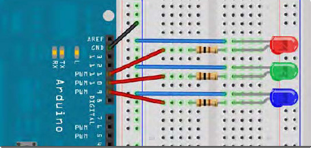
Figure 3-4. The circuit for Project 8 – RGB Mood Lamp (see insert for color version)
Enter the Code
Open up your Arduino IDE and type in the code from Listing 3-4.
Listing 3-4. Code for Project 8
// Project 8 - Mood Lamp

float RGB1[3];

float RGB2[3];

float INC[3];


int red, green, blue;


int RedPin = 11;

int GreenPin = 10;

int BluePin = 9;


void setup()
{

        randomSeed(analogRead(0));


        RGB1[0] = 0;

        RGB1[1] = 0;

        RGB1[2] = 0;


        RGB2[0] = random(256);

        RGB2[1] = random(256);

        RGB2[2] = random(256);

}


void loop()

{

        randomSeed(analogRead(0));


      for (int x=0; x<3; x++) {

                INC[x] = (RGB1[x] - RGB2[x]) / 256; }


        for (int x=0; x<256; x++) {

                red = int(RGB1[0]);

                green = int(RGB1[1]);

                blue = int(RGB1[2]);


                analogWrite (RedPin, red);
                analogWrite (GreenPin, green);

                analogWrite (BluePin, blue);

                delay(100);


                RGB1[0] -= INC[0];

                RGB1[1] -= INC[1];

                RGB1[2] -= INC[2];

        }
        for (int x=0; x<3; x++) {

              RGB2[x] = random(556)-300;

              RGB2[x] = constrain(RGB2[x], 0, 255);

              delay(1000);

        }

}
When you run this, you will see the colors slowly change. You've just made your own mood lamp!
Project 8 – RGB Mood Lamp – Code Overview
The LEDs that make up the mood lamp are red, green, and blue. In the same way that your computer monitor is made up of tiny red, green, and blue (RGB) dots, you can generate different colors by adjusting the brightness of each of the three LEDs in such a way to give you a different RGB value.
Alternatively, you could have used an RGB LED. This is a single 5mm LED, with 4 legs (some have more). One leg is either a common anode (positive) or common cathode (negative); the other three legs go to the opposite terminal of the red, green, and blue LEDs inside the lamp. It is basically three colored LEDs squeezed into a single 5mm LED. These are more compact, but more expensive.
An RGB value of 255, 0, 0 is pure red. A value of 0, 255, 0 is pure green and 0, 0, 255 is pure blue. By mixing these, you can get any color. This is the additive color model (see Figure 3-5). Note that if you were just turning the LEDs ON or OFF (i.e. not trying out different brightness) you would still get different colors.
Table 3-5. Colors available by turning LEDs ON or OFF in different combinations
| Red | Green | Blue | Color |
| 255 0 | 0 | Red | |
| 0 255 | 0 | Green | |
| 0 0 255 | Blue | ||
| 255 255 | 0 | Yellow | |
| 0 255 | 255 | Cyan | |
| 255 0 | 255 | Magenta | |
| 255 255 | 255 | White |
Diffusing the light with the paper cylinder mixes the colors nicely. The LEDs can be placed into any object that will diffuse the light; another option is to bounce the light off a reflective diffuser. Try putting the lights inside a ping-pong ball or a small white plastic bottle (the thinner the plastic the better).
By adjusting the brightness using PWM, you can get every other color in between, too. By placing the LEDs close together and mixing their values, the light spectra of the three colors added together make a single color (see Figure 3-5). The total range of colors available using PWM with a range of 0 to 255 is 16,777,216 colors (256x256x256).
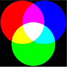
Figure 3-5. Mixing R, G, and B to get different colors (see insert for color version)
In the code, you begin by declaring some floating point arrays and some integer variables to store your RGB values as well as an increment value, like so:
float RGB1[3];

float RGB2[3];

float INC[3];


int red, green, blue;
In the setup function, you have the following:
randomSeed(analogRead(0));
The randomSeed command creates random (actually pseudo-random) numbers. A computer chip is not able to produce truly random numbers so it looks at data in a part of its memory that may differ or it looks at a table of different values and uses those as pseudo-random numbers. By setting a seed, you can tell the computer where in memory or in that table to start counting from. In this case, the value you assign to randomSeed is a value read from Analog Pin 0. Because there's nothing connected to Analog Pin 0, all it will read is a random number created by analog noise.
Once you have set a seed for your random number, you can create one using the random() function. You then have two sets of RGB values stored in a three element array. RGB1 contains the RGB values you want the lamp to start with (in this case, all zeros, or off):
  RGB1[0] = 0;

  RGB1[1] = 0;

  RGB1[2] = 0;
The RGB2 array is a set of random RGB values that you want the lamp to transition to:
  RGB2[0] = random(256);

  RGB2[1] = random(256);

  RGB2[2] = random(256);
In this case, you have set them to a random number set by random(256) which will give you a number between 0 and 255 inclusive (as the number will always range from zero upwards).
If you pass a single number to the random() function, it will return a value between 0 and 1 less than the number, e.g. random(1000) will return a number between 0 and 999. If you supply two numbers as the parameters, it will return a random number between the lower number inclusive and the maximum number (-1), e.g. random(10,100) will return a random number between 10 and 99.
In the main program loop, you first take a look at the start and end RGB values and work out what value is needed as an increment to progress from one value to the other in 256 steps (as the PWM value can only be between 0 and 255). You do this with the following:
   for (int x=0; x<3; x++) {

          INC[x] = (RGB1[x] - RGB2[x]) / 256; }
This for loop sets the INCrement values for the R, G and B channels by working out the difference between the two brightness values and dividing that by 256.
You have another for loop
   for (int x=0; x<256; x++) {


          red = int(RGB1[0]);

          green = int(RGB1[1]);

          blue = int(RGB1[2]);


          analogWrite (RedPin, red);
          analogWrite (GreenPin, green);

          analogWrite (BluePin, blue);

          delay(100);


          RGB1[0] -= INC[0];

          RGB1[1] -= INC[1];

          RGB1[2] -= INC[2];

  }
that sets the red, green, and blue values to the values in the RGB1 array; writes those values to Digital Pins 9, 10 and 11; deducts the increment value; and repeats this process 256 times to slowly fade from one random color to the next. The delay of 100ms in between each step ensures a slow and steady progression. You can, of course, adjust this value if you want it slower or faster; you can also add a potentiometer to allow the user to set the speed.
After you have taken 256 slow steps from one random color to the next, the RGB1 array will have the same values (nearly) as the RGB2 array. You now need to decide upon another set of three random values ready for the next time. You do this with another for loop:
 for (int x=0; x<3; x++) {

        RGB2[x] = random(556)-300;

        RGB2[x] = constrain(RGB2[x], 0, 255);

        delay(1000);

 }
The random number is chosen by picking a random number between 0 and 556 (256+300) and then deducting 300. In this manner, you are trying to force primary colors from time to time to ensure that you don't always just get pastel shades. You have 300 chances out of 556 in getting a negative number and therefore forcing a bias towards one or more of the other two color channels. The next command makes sure that the numbers sent to the PWM pins are not negative by using the constrain() function.
The constrain() function requires three parameters: x, a, and b where x is the number you want to constrain, a is the lower end of the range, and b is the higher end. So, the constrain() function looks at the value of x and makes sure it is within the range of a to b. If it is lower than a, it sets it to a; if it is higher than b, it sets it to b. In your case, you make sure that the number is between 0 and 255 which is the range of your PWM output.
As you use random(556)-300 for your RGB values, some of those values will be lower than zero; the constrain function makes sure that the value sent to the PWM is not lower than zero.
EXERCISE