Project 23 – Basic LCD Control
To start with, you will create a demonstration project that will show off most of the functions available in the LiquidCrystal.h library. To do so, you'll use a backlit 16×2 LCD Display.
Parts Required
You need to obtain an LCD Display that uses the HD44780 driver. There are many available and they come in all kinds of colors. As an amateur astronomer, I particularly like the red on black displays (red text on a black background) because they preserve your night vision if used in astronomy based projects. You can choose another color text and background but your display must have a backlight and be able to display sixteen columns and two rows of characters (often referred to as 16×2 LCD displays).
16×2 Backlit LCD 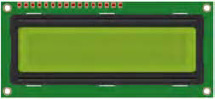
Current Limiting Resistor (Backlight) ![]()
Current Limiting Resistor (Contrast) ![]()
Connect It Up
The circuit for Project 23 is quite simple. Find the datasheet for the LCD you are using. The following pins (see Table 8-1) from the Arduino, +5v, and Ground need to go to the LCD.
Table 8-1. Pins to use for the LCD
| Arduino | Other | Matrix |
| Digital 11 | Enable | |
| Digital 12 | RS (Register Select) | |
| Digital 5 | DB4 (Data Pin 4) | |
| Digital 4 | DB5 (Data Pin 5) | |
| Digital 3 | DB6 (Data Pin 6) | |
| Digital 2 | DB7 (Data Pin 7) | |
| Gnd | Vss (GND) | |
| Gnd | R/W (Read/Write) | |
| +5v | Vdd | |
| +5v via resistor | Vo (Contrast) | |
| +5v via resistor | A/Vee (Power for LED) | |
| Gnd | Gnd for LED |
Data Pins 0 to 3 are not used because you are going to use what is known as 4-bit mode. For a typical LCD display the circuit in Figure 8-1 will be correct.
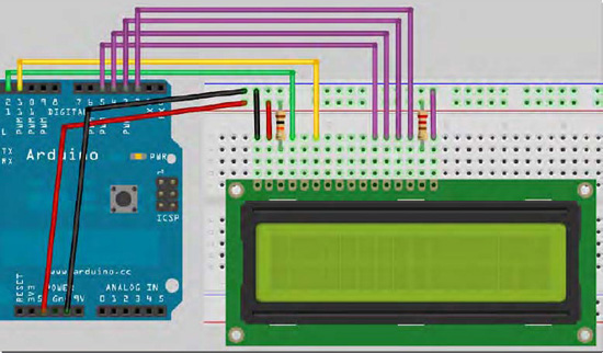
Figure 8-1. The circuit for Project 23 – Basic LCD Control (see insert for color version)
The contract adjustment pin on the LCD must be connected via a current limiting resistor in order to adjust the contrast the desired level. A value of around 10K ohm should suffice. If you find it difficult to get the right value, then connect a potentiometer (with value between about 4K ohm to 10K ohm) with the left leg to +5v, the right leg to ground, and the center leg to the contrast adjustment pin (Pin 3 on my test LCD). Now you can use the knob to adjust the contrast until you can see the display clearly.
The backlight on my test LCD required 4.2v, so I added the appropriate current limiting resistor between +5v and the LED power supply pin (Pin 15 on my LCD). You could connect the LED power pin to a PWM pin on the Arduino and use a PWM output to control the brightness of the backlight, but for simplicity's sake you won't use this method in this project. Once you're happy that you have the correct pins going between the Arduino, +5v, and Ground (according to the LCDs datasheet), you can enter the code
Enter The Code
Check your wiring, then upload the code from Listing 8-1.
Listing 8-1. Code for Project 23
// PROJECT 23

#include <LiquidCrystal.h>


// Initialize the library with the numbers of the interface pins

LiquidCrystal lcd(12, 11, 5, 4, 3, 2); // Create an lcd object and assign the pins
void setup() {

        lcd.begin(16, 2); // Set the display to 16 columns and 2 rows

}


void loop() {

        // Run the seven demo routines

        basicPrintDemo();

        displayOnOffDemo();

        setCursorDemo();

        scrollLeftDemo();

        scrollRightDemo();

        cursorDemo();

        createGlyphDemo();

}


void basicPrintDemo() {

        lcd.clear(); // Clear the display

        lcd.print("Basic Print"); // Print some text

        delay(2000);

}


void displayOnOffDemo() {

        lcd.clear(); // Clear the display

        lcd.print("Display On/Off"); // Print some text

        for(int x=0; x < 3; x++) { // Loop 3 times

                lcd.noDisplay(); // Turn display off

                delay(1000);

                lcd.display(); // Turn it back on again

                delay(1000);

        }

}


void setCursorDemo() {

        lcd.clear(); // Clear the display

        lcd.print("SetCursor Demo"); // Print some text

        delay(1000);

        lcd.clear(); // Clear the display

        lcd.setCursor(5,0); // Cursor at column 5 row 0

        lcd.print("5,0");

        delay(2000);

        lcd.setCursor(10,1); // Cursor at column 10 row 1

        lcd.print("10,1");

        delay(2000);

        lcd.setCursor(3,1); // Cursor at column 3 row 1

        lcd.print("3,1");

        delay(2000);

}
void scrollLeftDemo() {

        lcd.clear(); // Clear the display

        lcd.print("Scroll Left Demo");

        delay(1000);

        lcd.clear(); // Clear the display

        lcd.setCursor(7,0);

        lcd.print("Beginning");

        lcd.setCursor(9,1);

        lcd.print("Arduino");

        delay(1000);

        for(int x=0; x<16; x++) {

                lcd.scrollDisplayLeft(); // Scroll display left 16 times

                delay(250);

        }

}


void scrollRightDemo() {

        lcd.clear(); // Clear the display

        lcd.print("Scroll Right");

        lcd.setCursor(0,1);

        lcd.print("Demo");

        delay(1000);

        lcd.clear(); // Clear the display

        lcd.print("Beginning");

        lcd.setCursor(0,1);

        lcd.print("Arduino");

        delay(1000);

        for(int x=0; x<16; x++) {

                lcd.scrollDisplayRight(); // Scroll display right 16 times

                delay(250);

        }

}


void cursorDemo() {

        lcd.clear(); // Clear the display

        lcd.cursor(); // Enable cursor visible

        lcd.print("Cursor On");

        delay(3000);

        lcd.clear(); // Clear the display

        lcd.noCursor(); // Cursor invisible

        lcd.print("Cursor Off");

        delay(3000);

        lcd.clear(); // Clear the display

        lcd.cursor(); // Cursor visible

        lcd.blink(); // Cursor blinking

        lcd.print("Cursor Blink On");

        delay(3000);

        lcd.noCursor(); // Cursor invisible

        lcd.noBlink(); // Blink off

}
void createGlyphDemo() {

        lcd.clear();


        byte happy[8] = { // Create byte array with happy face
        B00000,

        B00000,

        B10001,

        B00000,

        B10001,

        B01110,

        B00000,

        B00000};


        byte sad[8] = { // Create byte array with sad face

        B00000,

        B00000,

        B10001,

        B00000,

        B01110,

        B10001,

        B00000,

        B00000};


        lcd.createChar(0, happy); // Create custom character 0

        lcd.createChar(1, sad); // Create custom character 1


        for(int x=0; x<5; x++) { // Loop animation 5 times

                lcd.setCursor(8,0);

                lcd.write(0); // Write custom char 0

                delay(1000);

                lcd.setCursor(8,0);

                lcd.write(1); // Write custom char 1

                delay(1000);

        }

}
Project 23 – Basic LCD Control – Code Overview
First you load in the library that you are going to use to control the LCD. There are many libraries and code examples available for different types of LCDs; you can find them all on the Arduino playground at www.arduino.cc/playground/Code/LCD. However, the Arduino IDE comes with a library called LiquidCrystal.h that is easy to understand and use:
#include <LiquidCrystal.h>
Now you need to create and LiquidCrystal object and set the appropriate pins:
LiquidCrystal lcd(12, 11, 5, 4, 3, 2); // Create an lcd object and assign the pins
So you have created a LiquidCrystal object and called it lcd. The first two parameters set the pins for RS (Register Select) and Enable. The last four parameters are Data Pins D4 to D7. As you are using 4-bit mode, you are only using four of the eight data pins on the display.
The difference between 4-bit and 8-bit modes is that in 8-bit mode you can send data one byte at a time whereas in 4-bit mode the 8 bits have to be split up into to 4-bit numbers (known as nibbles). This makes the code larger and more complex. However, you are using a readymade library, so you don't need to worry about that. If, however, you were writing space- or time-critical code, you would consider writing directly to the LCD in 8-bit mode. Using 4-bit mode has the advantage of saving four pins which is useful if you want to connect other devices at the same time.
In the setup() loop you initialize the display to the size required, which is 16 columns and 2 rows:
lcd.begin(16, 2); // Set the display to 16 columns and 2 rows
The main program loop simply runs seven different demo routines, one by one, before restarting. Each demo routine shows off one set of related routines in the LiquidCrystal.h library:
void loop() {

        // Run the seven demo routines

        basicPrintDemo();

        displayOnOffDemo();

        setCursorDemo();

        scrollLeftDemo();

        scrollRightDemo();

        cursorDemo();

        createGlyphDemo();

}
The first function is basicPrintDemo() and it is designed to show use of the .print() command. This demo simply clears the display using lcd.clear() and then prints to the display using lcd.print(). Note that if you had initialized your LiquidCrystal object and called it, for example, LCD1602, then these commands would be LCD1602.clear() and LCD1602.print() accordingly. In other words, the command comes after the name of the object, with a dot between them.
The print() command will print whatever is inside the brackets at the current cursor location. The default cursor location is always column 0 and row 0, which is the top right corner. After clearing the display, the cursor will be set to the default or home position.
void basicPrintDemo() {

        lcd.clear(); // Clear the display

        lcd.print("Basic Print"); // Print some text

        delay(2000);

}
The second function is designed to show off the display() and noDisplay() commands. These commands simply enable or disable the display. The routine prints out “Display On/Off” and then runs a loop three times to turn the display off, wait one second, turn it back on, wait another second, then repeat. Whenever you turn the display off, whatever was printed on the screen before it went off will be preserved when the display is re-enabled.
void displayOnOffDemo() {

        lcd.clear(); // Clear the display

        lcd.print("Display On/Off"); // Print some text

        for(int x=0; x < 3; x++) { // Loop 3 times

                lcd.noDisplay(); // Turn display off

                delay(1000);

                lcd.display(); // Turn it back on again

                delay(1000);

        }

}
The next function shows off the setCursor() command, which sets the cursor to the column and row location set within the brackets. The demonstration sets the cursor to three locations and prints that location in text on the display. The setCursor() command is useful for controlling the layout of your text and ensuring that your output goes to the appropriate part of the display screen.
void setCursorDemo() {

        lcd.clear(); // Clear the display

        lcd.print("SetCursor Demo"); // Print some text

        delay(1000);

        lcd.clear(); // Clear the display

        lcd.setCursor(5,0); // Cursor at column 5 row 0

        lcd.print("5,0");

        delay(2000);

        lcd.setCursor(10,1); // Cursor at column 10 row 1

        lcd.print("10,1");

        delay(2000);

        lcd.setCursor(3,1); // Cursor at column 3 row 1

        lcd.print("3,1");

        delay(2000);

}
There are two commands in the library for scrolling text: scrollDisplayLeft() and scrollDisplayRight(). Two demo routines show off these commands. The first prints “Beginning Arduino” on the right side of the display and scrolls it left 16 times, which will make it scroll off the screen:
void scrollLeftDemo() {

        lcd.clear(); // Clear the display

        lcd.print("Scroll Left Demo");

        delay(1000);

        lcd.clear(); // Clear the display

        lcd.setCursor(7,0);

        lcd.print("Beginning");

        lcd.setCursor(9,1);

        lcd.print("Arduino");

        delay(1000);
        for(int x=0; x<16; x++) {

                lcd.scrollDisplayLeft(); // Scroll display left 16 times

                delay(250);

        }

}
The next function acts similarly, starting with the text on the left and scrolling it right 16 times till it scrolls off the screen:
void scrollRightDemo() {

        lcd.clear(); // Clear the display

        lcd.print("Scroll Right");

        lcd.setCursor(0,1);

        lcd.print("Demo");

        delay(1000);

        lcd.clear(); // Clear the display

        lcd.print("Beginning");

        lcd.setCursor(0,1);

        lcd.print("Arduino");

        delay(1000);

        for(int x=0; x<16; x++) {

                lcd.scrollDisplayRight(); // Scroll display right 16 times

                delay(250);

        }

}
The cursor so far has been invisible—it's always there but just not seen. Whenever you clear the display, the cursor returns to the top left corner (column 0 and row 0). After printing some text, the cursor will sit just after the last character printed. The next function clears the display, then turns the cursor on with cursor() and prints some text. The cursor will be visible, just after this text, as an underscore (_) symbol:
void cursorDemo() {

        lcd.clear(); // Clear the display

        lcd.cursor(); // Enable cursor visible

        lcd.print("Cursor On");

        delay(3000);
The display is cleared again. This time the cursor is turned off, which is the default mode, using noCursor(). Now the cursor cannot be seen:
        lcd.clear(); // Clear the display

        lcd.noCursor(); // Cursor invisible

        lcd.print("Cursor Off");

        delay(3000);
Next, the cursor is enabled again. Blink mode is also enabled using blink():
        lcd.clear(); // Clear the display

        lcd.cursor(); // Cursor visible

        lcd.blink(); // Cursor blinking

        lcd.print("Cursor Blink On");

        delay(3000);
This time the cursor will not only be visible, but will be blinking on and off. This mode is useful if you are waiting for some text input from a user. The blinking cursor will act as a prompt to enter some text.
Finally, the cursor and blink are turned off to put the cursor back into the default mode:
        lcd.noCursor(); // Cursor invisible

        lcd.noBlink(); // Blink off

}
The final function called createGlyphDemo() creates a custom character. Most LCDs let you program your own custom characters to them. The standard 16×2 LCD has space to store eight custom characters in memory. The characters are 5 pixels wide by 8 pixels high (a pixel is a picture element, i.e. the individual dots that make up a digital display). The display is cleared and then two arrays of type byte are initialized with the binary pattern of a happy and a sad face. The binary patterns are 5 bits wide.
void createGlyphDemo() {

        lcd.clear();


        byte happy[8] = { // Create byte array with happy face

        B00000,

        B00000,

        B10001,

        B00000,

        B10001,

        B01110,

        B00000,

        B00000};


        byte sad[8] = { // Create byte array with sad face

        B00000,

        B00000,

        B10001,

        B00000,

        B01110,

        B10001,

        B00000,

        B00000};
Then you create the two custom characters using the createChar() command. This requires two parameters: the first is the number of the custom character (0 to 7 in the case of my test LCD, which can store a maximum of 8), and the second is the name of the array that creates and stores the custom characters binary pattern in memory on the LCD:
        lcd.createChar(0, happy); // create custom character 0

        lcd.createChar(1, sad); // create custom character 1
A for loop will now loop through itself five times. On each iteration the cursor is set to column 8 and row 0, and the first custom character is written to that location using the write() command. This writes the custom character within the brackets to the cursor location. The first character, a happy face, is written to the cursor location; after a delay of one second the second character, a sad face, is then written to the same cursor location. This repeats five times to make a crude animation.
        for(int x=0; x<5; x++) { // loop animation 5 times

                lcd.setCursor(8,0);

                lcd.write(0); // write custom char 0

                delay(1000);

                lcd.setCursor(8,0);

                lcd.write(1); // write custom char 1

                delay(1000);

        }

}
Project 23 covered most of the popular commands within the LiquidCrystal.h library. There are several others to discover, however, and you can read about them in the Arduino Reference library at www.arduino.cc/en/Reference/LiquidCrystal.
Project 23 – Basic LCD Control – Hardware Overview
The new component in this project was obviously the LCD. A liquid crystal display works by using the light modulating properties of liquid crystals. The display is made up of pixels, each one filled with liquid crystals. These pixels are arrayed in front of a backlighting source or a reflector. The crystals are placed into layers sandwiched between polarizing filters. The two polarizing panels are aligned at 90 degrees to each other, which blocks light. The first polarizing filter will polarize the light waves so that they all run in one orientation only. The second filter, being at 90 degrees to the first, will block the light. In other words, imagine that the filter is made up of very thin slits going in one direction. Light polarized in one direction will go through slits in the same orientation, but when it reaches the second filter, which has its slits running the other way, it will not pass through. By running a current across the rows and columns of the layers, the crystals can be made to change orientation and line up with the electric field. This causes the light to twist 90 degrees, thus allowing it through the second filter. Hence, some displays are referred to as “Super-Twist.”
The LCD is made up of a grid of pixels and these are arranged into smaller grids that make up the characters. A typical 16×2 LCD will have 16 character grids in two rows. Each character grid is made up of 5 pixels wide by 8 pixels high. If you turn the contrast up very high on your display, the 32 arrays of 5×7 pixels will become visible.
That is really all you need to know about how LCDs work. Let's now put the LCD to use by making a temperature display.