Project 22 – LED Dot Matrix Display – Pong Game
Project 21 was hard going and a lot to take in. So, for Project 22 you are going to create a simple game with simple code using the dot matrix display and a potentiometer. This time you are going to use one of the many available libraries for controlling LED dot matrix displays to see how much easier it can make your life when coding.
Parts Required
The parts required are the same as Project 21 with the addition of a 10KΩ Potentiometer
Same as Project 21 plus….
10KΩ Potentiometer 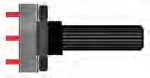
Connect It Up
Leave the circuit the same as in Project 21 and add a potentiometer. The left and right pins go to Ground and +5V, respectively, and the center pin goes to Analog Pin 5.

Figure 7-8. Add a potentiometer to the Project 21 circuit (see insert for color version)
Upload the Code
Upload the code from Listing 7-4. When the program is run, a ball will start from a random location on the left and head towards the right. Using the potentiometer, control the paddle to bounce the ball back towards the wall. As time goes by, the speed of the ball will increase faster and faster until you will not be able to keep up with it.
When the ball bounces past the paddle, the screen will flash and the game will restart. See how long you can go for before the game resets.
Listing 7-4. Code for Project 21
//Project 22

#include "LedControl.h"


LedControl myMatrix = LedControl(2, 4, 3, 1); // create an instance of a Matrix


int column = 1, row = random(8)+1; // decide where the ball will start

int directionX = 1, directionY = 1; // make sure it heads from left to right first

int paddle1 = 5, paddle1Val; // Pot pin and value

int speed = 300;

int counter = 0, mult = 10;


void setup()
{

        myMatrix.shutdown(0, false); // enable display

        myMatrix.setIntensity(0, 8); //  Set the brightness to medium

        myMatrix.clearDisplay(0); // clear the display

        randomSeed(analogRead(0));

}


void loop()
{

        paddle1Val = analogRead(paddle1);

        paddle1Val = map(paddle1Val, 200, 1024, 1,6);

        column += directionX;

        row += directionY;

        if (column == 6 && directionX == 1 && (paddle1Val == row || paddle1Val+1 ==

 row || paddle1Val+2 == row)) {directionX = -1;}

        if (column == 0 && directionX == -1 ) {directionX = 1;}

        if (row == 7 && directionY == 1 ) {directionY = -1;}

 if (row == 0 && directionY == -1 ) {directionY = 1;}

        if (column == 7) { oops();}

        myMatrix.clearDisplay(0); // clear the screen for next animation frame

        myMatrix.setLed(0, column, row, HIGH);

        myMatrix.setLed(0, 7, paddle1Val, HIGH);

        myMatrix.setLed(0, 7, paddle1Val+1, HIGH);

        myMatrix.setLed(0, 7, paddle1Val+2, HIGH);

        if (!(counter % mult)) {speed -= 5; mult * mult;}

        delay(speed);

        counter++;

}
void oops() {

        for (int x=0; x<3; x++) {

        myMatrix.clearDisplay(0);

        delay(250);

                for (int y=0; y<8; y++) {

                        myMatrix.setRow(0, y, 255);

                }

                delay(250);

        }

        counter=0; // reset all the values

        speed=300;

        column=1;

        row = random(8)+1; // choose a new starting location

}
Project 22 – LED Dot Matrix – Pong Game
The code for Project 22 is really simple. After all, you are taking a break from the hard work done in Project 21!
First, the LedControl.h library is included in the sketch. You will need to download the library and install it in the libraries folder as before. The library, as well as further information, can be found at www.arduino.cc/playground/Main/LedControl
#include "LedControl.h"
You then create an instance of an LedControl object like so
LedControl myMatrix = LedControl(2, 4, 3, 1); // create an instance of a Matrix
This creates an LedControl object called myMatrix. The LedControl object requires four parameters. The first three are the pin numbers for the MAX7219; the order is Data In, Clock, and Load. The final number is for the number of the chip (in case you are controlling more than one MAX7219 and display).
Then you decide which column and row the ball will start in. The row is decided using a random number.
int column = 1, row = random(8)+1; // decide where the ball will start
Now two integers are declared to decide the direction the ball will travel in. If the number is positive, it will head from left to right and bottom to top, respectively, and if negative, it will be in reverse.
int directionX = 1, directionY = 1; // make sure it heads from left to right first
You decide which pin is being used for the paddle (the potentiometer) and declare an integer to hold the value read from the analog pin:
int paddle1 = 5, paddle1Val; // Pot pin and value
The speed of the ball is declared in milliseconds:
int speed = 300;
Then you declare and initialize a counter to zero and its multiplier to 10:
int counter = 0, mult = 10;
The setup() function enables the display by ensuring that the powersaving mode is set to false. The intensity is set to medium and then the display is cleared in preparation for the game. Before you start, the randomSeed is set with a random value read from an unused analog pin.
void setup()

{

        myMatrix.shutdown(0, false); // enable display

        myMatrix.setIntensity(0, 8); //  Set the brightness to medium

        myMatrix.clearDisplay(0); // clear the display

        randomSeed(analogRead(0));

}
In the main loop, you start by reading the analog value from the paddle:
paddle1Val = analogRead(paddle1);
Then those values are mapped to between 1 and 6:
paddle1Val = map(paddle1Val, 200, 1024, 1,6);
The map command requires five parameters. The first is the number to map. Next are the low and high values of the number and the low high values you wish to map it to. In your case, you are taking the value in paddle1Val, which is the voltage read from Analog Pin 5. This value ranges from 0 at 0 volts to 1024 at 5 volts. You want those numbers mapped to read only between 1 and 6 as this is the row the paddle will be displayed on when drawn on the display.
The column and row coordinates are increased by the values in directionX and directionY:
column += directionX;

row += directionY;
You now need to decide if the ball has hit a wall or a paddle, and if so, bounce back (the exception being if it goes past the paddle0. The first if statement checks that the ball has hit the paddle. It does this by deciding if the column the ball is in is column 6 and (logical AND &&) is also heading left to right:
if (column == 6 && directionX == 1 && (paddle1Val == row ||

paddle1Val+1 == row || paddle1Val+2 == row)) {directionX = -1;}
There are three conditions that have to be met for the ball direction to change. The first is that the column is 6, second is that the direction is positive (i.e. left to right) and third is that the ball is on the same row that either of the 3 dots that make up the paddle is in. This is done by nesting a set of or (logical OR ||) commands inside brackets. The result of this calculation is checked first and then the result added to the three && statements in the first set of brackets.
The next three sets of if statements check if the ball has hit the top, bottom, or left side walls, and if so, reverses the ball direction:
if (column == 0 && directionX == -1 ) {directionX = 1;}

if (row == 7 && directionY == 1 ) {directionY = -1;}

if (row == 0 && directionY == -1 ) {directionY = 1;}
Finally, if the ball is in column 7, it has obviously not hit the paddle but has gone past it. If that is the case, call the oops() function to flash the display and reset the values:
if (column == 7) { oops();}
Next the display is cleared to erase any previous dots:
myMatrix.clearDisplay(0); // clear the screen for next animation frame
The ball is drawn at the column and row location. This is done with the .setLed command of the LedControl library:
myMatrix.setLed(0, column, row, HIGH);
The .setLed command requires four parameters. The first number is the address of the display, then the x and y (or column and row) co-ordinates and finally a HIGH or LOW for on and off. These are used again to draw the three dots that make up the paddle at column 7 and row paddle1Val (plus one above and one above that).
myMatrix.setLed(0, 7, paddle1Val, HIGH);

myMatrix.setLed(0, 7, paddle1Val+1, HIGH);

myMatrix.setLed(0, 7, paddle1Val+2, HIGH);
You then check if the modulo of counter % mult is NOT (logical NOT !) true, and if so, decrease the speed by five and multiply the multiplier by itself. Modulo is the remainder when you divide one integer by another. In your case, you divide counter by mult and check if the remainder is a whole number or not. This basically ensures that the speed is only increased after a set time and that the time increases proportionally to the decreasing delay.
if (!(counter % mult)) {speed -= 5; mult * mult;}
A delay in milliseconds of the value of speed is activated and then the counter value is increased by one:
delay(speed);

counter++;

}
Finally, the oops() function causes a for loop within a for loop to clear the display and then fills in all rows repeatedly with a 250 millisecond delay in between. This makes all LEDs flash on and off to indicate the ball has gone out of play and the game is about to reset. Then all of the values of counter, speed, and column are set to their starting positions and a new random value chosen for row.
void oops() {

for (int x=0; x<3; x++) {

myMatrix.clearDisplay(0);

delay(250);
                for (int y=0; y<8; y++) {

                        myMatrix.setRow(0, y, 255);

                }

                delay(250);

        }

        counter=0; // reset all the values

        speed=300;

        column=1;

        row = random(8)+1; // choose a new starting location

}
The .setRow command works by passing the address of the display, the row value, and then the binary pattern of which LEDs to turn on or off. In this case, you want them all on, which is binary 11111111 and decimal 255.
The purpose of Project 22 was to show how much easier it is to control an LED Driver chip if you use a ready-made library of code designed for the chip. In Project 21, you did it the hard way coding everything from scratch; in Project 22, the hard work was all done for you behind the scenes. There are other Matrix libraries available; in fact, the Arduino IDE comes with one called matrix. I had better luck with the LedControl.h library myself and so I chose that. You can use whichever library suits your needs best.
In the next chapter, you will look at a different type of dot matrix display, the LCD.