Project 31 – Digital Pressure Sensor
You are going to use an Arduino Mega for this project because Project 32 uses a GLCD and you'll need the extra pins the Mega provides. If you don't have a Mega, you can still use a standard Arduino—just change the SPI pins to match those of a Duemilanove.
Parts Required
The tiny SCP1000 sensor can be purchased from Sparkfun or their distributors pre-soldered to a breakout board (see Figure 11-1) to make it easy to interface with an Arduino (or other microcontroller). You will need to solder some header pins onto the board if you wish to push it into a breadboard. Otherwise, solder some wires to it so it can be connected to the Mega.
| Arduino Mega |  |
| SCP1000 Pressure Sensor |  |
| 3 × 10KΩ Resistors | |
| 1 × 1KΩ Resistor |
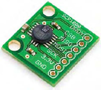
Figure 11-1. The SCP1000 on a Sparkfun breakout board
Connect It Up
Connect everything as shown in Figure 11-2.
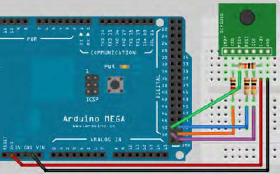
Figure 11-2. The circuit for Project 31 – Digital Pressure Sensor (see insert for color version)
The sensor has a TRIG and PD pins that will need to be connected to Ground, too. Make sure that everything is connected up correctly, especially the resistors as these will protect the SCP1000 from over voltage. Now enter the code.
Enter the Code
Enter the code from Listing 11-1.
Listing 11-1. Code for Project 31
/*

SCP1000             Mega

DRDY                N/A

CSB                 53 via Logic Level Convertor

MISO                50 (straight through)

MOSI                51 via Logic Level Convertor

SCK                 52 via Logic Level Convertor

3.3v                3.3v

GND                 GND

TRIG                GND

PD                  GND

*/


// SPI PINS
#define SLAVESELECT 53

#define SPICLOCK 52

#define DATAOUT 51  //MOSI

#define DATAIN 50   //MISO

#define UBLB(a,b)  ( ( (a) << 8) | (b) )

#define UBLB19(a,b) ( ( (a) << 16 ) | (b) )


//Addresses
#define PRESSURE 0x1F   //Pressure 3 MSB

#define PRESSURE_LSB 0x20 //Pressure 16 LSB

#define TEMP 0x21       //16 bit temp


char rev_in_byte;
int temp_in;

unsigned long pressure_lsb;

unsigned long pressure_msb;

unsigned long temp_pressure;

unsigned long pressure;
void setup()

{

        byte clr;

        pinMode(DATAOUT, OUTPUT);

        pinMode(DATAIN, INPUT);

        pinMode(SPICLOCK, OUTPUT);

        pinMode(SLAVESELECT, OUTPUT);

        digitalWrite(SLAVESELECT, HIGH); //disable device


        SPCR = B01010011; // SPi Control Register
        //MPIE=0, SPE=1 (on), DORD=0 (MSB first), MSTR=1 (master), CPOL=0 (clock idle when

 low), CPHA=0 (samples MOSI on rising edge), SPR1=0 & SPR0=0 (500kHz)

        clr=SPSR; // SPi Status Register

        clr=SPDR; // SPi Data Register

        delay(10);

        Serial.begin(38400);

        delay(500);


        write_register(0x03,0x09); // High Speed Read Mode
        write_register(0x03,0x0A); // High Resolution Measurement Mode

}


void loop()
{

        pressure_msb = read_register(PRESSURE);

        pressure_msb &= B00000111;

        pressure_lsb = read_register16(PRESSURE_LSB);

        pressure_lsb &= 0x0000FFFF;

        pressure = UBLB19(pressure_msb, pressure_lsb);

        pressure /= 4;


        Serial.print("Pressure (hPa): ");
        float hPa = float(pressure)/100;

        Serial.println(hPa);


        Serial.print("Pressure (Atm): ");
        float pAtm = float(pressure)/101325.0;

        Serial.println(pAtm, 3);


        temp_in = read_register16(TEMP);
        float tempC = float(temp_in)/20.0;

        Serial.print("Temp. C: ");

        Serial.println(tempC);

        float tempF = (tempC*1.8) + 32;

        Serial.print("Temp. F: ");

        Serial.println(tempF);

        Serial.println();

        delay(1000);

}
char spi_transfer(char data)

{

        SPDR = data;                     // Start transmission

        while (!(SPSR & (1<<SPIF))) { }; // Wait for transmission end

        return SPDR;                     // return the received byte

}


char read_register(char register_name)
{

        char in_byte;

        register_name <<= 2;

        register_name &= B11111100; //Read command


        digitalWrite(SLAVESELECT, LOW); //Enable SPI Device
        spi_transfer(register_name); //Write byte to device

        in_byte = spi_transfer(0x00); //Send nothing but get back register value

        digitalWrite(SLAVESELECT, HIGH); // Disable SPI Device

        delay(10);

        return(in_byte); // return value

}


unsigned long read_register16(char register_name)
{

        byte in_byte1;

        byte in_byte2;

        float in_word;


        register_name <<= 2;
        register_name &= B11111100; //Read command


        digitalWrite(SLAVESELECT, LOW); //Enable SPI Device
        spi_transfer(register_name); //Write byte to device

        in_byte1 = spi_transfer(0x00);

        in_byte2 = spi_transfer(0x00);

        digitalWrite(SLAVESELECT, HIGH); // Disable SPI Device

        in_word = UBLB(in_byte1,in_byte2);

        return(in_word); // return value

}


void write_register(char register_name, char register_value)
{

        register_name <<= 2;

        register_name |= B00000010; //Write command


        digitalWrite(SLAVESELECT, LOW); //Select SPI device
        spi_transfer(register_name); //Send register location

        spi_transfer(register_value); //Send value to record into register

        digitalWrite(SLAVESELECT, HIGH);

}
This code is based on work by Conor and a few others from the Arduino forums, so thanks to those involved. Also, version 0019 of the Arduino IDE came in an SPI example sketch for the SCP1000 using the SPI.h library by Tom Igoe.
The code above does things the hard way again so that you can see exactly how the SCP1000 communicates with the Arduino. Once you understand it, you can make life easier by using the SPI library.
After you have uploaded the code, open up the serial monitor window and ensure that your baud rate is set to 38400. You will see a stream of data from the sensor showing the pressure in hPa (hectopascals) and in atmospheres. Hectopascals are the unit of pressure commonly used in weather forecasts. You will also see the temperature in Celsius and Fahrenheit.
Project 31 – Digital Pressure Sensor – Code Overview
The code starts off with a set of defines for your pins on the Mega:
#define SLAVESELECT 53

#define SPICLOCK 52

#define DATAOUT 51  //MOSI

#define DATAIN 50   //MISO
If you are using a Duemilanove, the pins will be:
#define SLAVESELECT 10

#define SPICLOCK 13

#define DATAOUT 11  //MOSI

#define DATAIN 12   //MISO
Next are another two defines that are cleverly designed to do some bitshifting for you:
#define UBLB(a,b)  ( ( (a) << 8) | (b) )

#define UBLB19(a,b) ( ( (a) << 16 ) | (b) )
The first one will take two 8 bit digits and convert them to a 16 bit digit by using one as the LSB (least significant byte) and the other as the MSB (most significant byte). It does this with some bit shifting and some bitwise operations.
For example, if you had two 8 bit numbers (10010101 and 00111001) and you put them into the equation
UBLB(a,b) ( ( (a) << 8) | (b) )
the calculation works out as
(((B10010101) << 8) | (B00111001))
So, the first digit is bit shifted left eight times to create
B1001010100000000
This number is then bitwise OR'ed with the second digit to create
B1001010100111001
So it has simply taken two 8 bit numbers and converted them into a 16 bit number using one set of 8 bits as the MSB and the other as the LSB.
The second define does something similar:
#define UBLB19(a,b) ( ( (a) << 16 ) | (b) )
This time it will create a 19 bit number, which is the resolution of the SCP1000 pressure sensor. It does this bit shifting the first 3 bits sixteen places to the left leaving 16 bits clear to add the 16 bit digit stored in b.
Next, you define the three registers inside the sensor that must be read in order to obtain the pressure data and the temperature:
#define PRESSURE 0x1F   //Pressure 3 MSB

#define PRESSURE_LSB 0x20 //Pressure 16 LSB

#define TEMP 0x21       //16 bit temp
The PRESSURE register at address 0x1F holds the three most significant bits of the 19 digit number that makes up the pressure reading. The PRESSURE_LSB register at address 0x20 holds the next 16 digits of the number. By using the calculation defined in UBLB19(a,b) the 16 bit and 3 bit numbers will be combined to create one 19 bit number.
Next, you declare some variables that will be used to store the values read from the pressure and temperature sensors:
char rev_in_byte;

int temp_in;

unsigned long pressure_lsb;

unsigned long pressure_msb;

unsigned long temp_pressure;

unsigned long pressure;
Next comes the setup routine. You start off by declaring a local variable of type byte (you will see how this is used soon):
byte clr;
Next, you set the four pins that make up the SPI bus to their respective INPUT and OUTPUT status:
pinMode(DATAOUT, OUTPUT);

pinMode(DATAIN, INPUT);

pinMode(SPICLOCK, OUTPUT);

pinMode(SLAVESELECT, OUTPUT);
Then you set the slave select pin to HIGH to disable the device as you don't want to exchange data with it while you are still setting up:
digitalWrite(SLAVESELECT, HIGH); //disable device
Next, you set SPCR to the binary value of B01010011:
SPCR = B01010011; // SPi Control Register
You may have noticed that this variable has not been declared yet, but the code will work. How can this be? Well, SPCR stands for SPI Control Register. It's one of three registers used in SPI communications that are hardcoded into the Arduino IDE. The other two are SPSR (SPI Status Register) and SPDR (SPI Data Register). Whenever you assign values to any of these registers, you will change what is going on with the SPI bus.
Let's take a little detour to look at SPI and how it works.
SPI – Serial Peripherals Interface
Before you look at the code any further, you need to understand what SPI is and how it works. SPI can be a complicated subject, so I am not going to go into it in any great depth. This is a beginner's book after all. Instead, I am going to give you just enough knowledge so that you understand what SPI is, how it works, and the parts that are relevant to the sketches in Projects 31 and 32 that use the SPI bus with the SCP1000 sensor. You will then be able to understand how to interface with other devices that also use SPI.
SPI is a way for two devices to exchange information. It has the benefits of needing only four pins from the Arduino and it's is fast. SPI is a synchronous protocol that allows a master device to communicate with a slave device. The data is controlled with a clock signal (CLK) which decides when data can change and when it is valid for reading. The clock rate can vary, unlike some other protocols in which the clock signal must be timed very accurately. This makes it ideal for microcontrollers that do not run particularly fast or whose internal oscillator is not clocked precisely.
SPI is a Master-Slave protocol (see Figure 11-3), meaning that a master device controls the clock signal. No data can be transmitted unless the clock is pulsed. SPI is also a data exchange protocol. This means that as data is clocked out, new data is being clocked in. Devices cannot simply transmit or receive data; they must exchange it, even if the data on one side is not being used in your program.
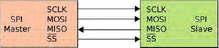
Figure 11-3. SPU bus: single master and single slave (image courtesy of Colin M.L. Burnett)
The slave select pin will control when a device can be accessed if more than one slave is attached to the master (see Figure 11-4). When there is only one slave device, as in your case, the SS (called CSB on the SCP1000) is optional. However, as a rule, it should be used regardless as it is also used as a reset for the slave to make it ready to receive the next byte. The slave select signal is sent out by the master to tell the slave that it wishes to start an SPI data exchange. This signal is active when LOW, so when held HIGH the slave device is not selected.
Data is only output during either the rising or falling edge of the clock signal on SCK. Data is latched during the opposite edge of SCK. The polarity of the clock is set by the master using one of the flags set in the SPCR register. The two data lines are known as MOSI (Master Output Slave Input) and MISO (Master Input Slave Output). So, if the device is set to send data from the master on the rising edge of the clock pulse, data would be sent back from the slave on the falling edge of the clock pulse. Data is therefore both sent (MOSI) and input (MISO) from the master during one clock pulse.

Figure 11-4. Left: A master with three independent slaves. Right: daisy chained slaves. (Images courtesy of Colin M.L. Burnett)
Remember that even if you only want to read data from a device (like you do with the SCP1000), you still need to send data both ways during one exchange.
The three registers used by the SPI bus are:
- SPCR – SPI Control Register
- SPDR – SPI Data Register
- SPSR – SPI Status Register
The Control Register has 8 bits and each bit controls a particular SPI setting. These bits are listed in Table 11-1.
Table 11-1. The SPI Control Register Settings
| 7 | 6 | 5 | 4 | 3 | 2 | 1 | 0 |
| SPIE SPE | DORD | MSTR | CPOL | CPHA | SPR1 | SPR0 |
- SPIE – SPI Interrupt Enable - Enables the SPI interrupt if 1.
- SPE – SPI Enable - SPI enabled when set to 1.
- DORD – Data Order - LSB transmitted first if 1 and MSB if 0.
- MSTR – Master/Slave Select – Sets Arduino in Master Mode if 1, Slave Mode when 0.
- CPOL – Clock Polarity – Sets Clock to be idle when high if set to 1, idle when low if set to 0.
- CPHA – Clock Phase – Determines if data is sampled on the leading or trailing edge of the clock.
- SPR1/0 – SPI Clock Rate Select 1 & 0 – These two bits control the clock rate of the master device.
The reason you can change these settings is that different SPI devices expect the clock polarity, clock phase, data order, speed, etc. to be different. This is mainly due to the fact that there is no standard for SPI, therefore manufacturers create devices with minor differences. In your code you set the SPCR thus:
SPCR = B01010011;
So you have disabled the interrupt (SPIE = 0), enabled the SPI (SPE = 1), set the data order to MSB first (DORD = 0), set the Arduino as master (MSTR = 1), set the clock polarity to be idle when low (CPOL = 0), set the clock phase to sample on the rising edge (CPHA = 0), and set the speed to be 250kHz (SPR1/2 = 11, which is 1/64th of the Arduino's oscillator frequency (16,000/64)).
The SPI Status Register (SPSR) uses 3 of its bits for setting the status of the SPI transfer. You are only interested in bit 7 (SPIF – SPI Interrupt Flag), which tells you if a serial transfer has been completed or not. If a transfer has been completed, it is set to 1. This bit is cleared (set to 0) by first reading the SPSR with bit 7 set to 1 and then the SPI Data Register (SPDR) is accessed.
The SPDR simply holds the byte that is going to be sent out of the MOSI line and read in from the MISO line.
All of the above sounds pretty complicated, but most of it you do not need to know (just yet). The SPI bus can be explained in layman's terms as having a master and slave device that want to talk to each other. The clock pulse ensures that data is sent from the master to the slave as the clock pulse rises (or falls, depending on how you have set the control register) and from the slave to the master as the clock falls (or rises). SPIF is set to 1 after the transfer is complete.
Now let's get back to the code.
Project 31 – Digital Pressure Sensor – Code Overview (cont.)
You now read in the SPSR and SPDR registers into clr. All this does is ensure that any junk data that may be in those registers is cleared out and the device is ready for you to use.
clr=SPSR; // SPi Status Register

clr=SPDR; // SPi Data Register
You then have a small delay, set the baud rate, followed by 500 millisecond delay to allow the serial line to set itself:
delay(10);

Serial.begin(38400);

delay(500);
You now use the write_register function (explained later) to write two values to the operation register address in the sensor, which is at Hexadecimal address 0x03. Writing a value of 0x09 to this register sets the sensor to high speed read mode and sending a value of 0x0A sets it to high resolution acquisition mode to ensure you get the most accurate value from the sensor.
write_register(0x03,0x09); // High Speed Read Mode

write_register(0x03,0x0A); // High Resolution Measurement Mode
Next comes your main loop. You start off by reading the value from the PRESSURE register (address 0x1F) and storing it in pressure_msb. This value will be the most significant byte of your 19 bit value (i.e. the 3 bits you need).
pressure_msb = read_register(PRESSURE);
Next you bit mask that value by carrying out a bitwise AND (&) with the value in pressure_msb and the binary number B00000111. Remember that the bitwise AND operator sets bits to 1 if both bits are 1 and to 0 if both bits are 0. Having the first three bits set to 1 (B00000111) means you will end up with only the first 3 bits, which is what you want.
pressure_msb &= B00000111;
You now want the remaining 16 bits of the pressure value so read the value stored in the PRESSURE_LSB register (address 0x20):
pressure_lsb = read_register16(PRESSURE_LSB);
Then you carry out a bitwise AND with this value and 0x0000FFFF, which is binary number B1111111111111111, meaning you only end up with the first 16 bits of any value read:
pressure_lsb &= 0x0000FFFF;
You then use the clever define trick in UBLB19 to take the 16 bits and the 3 bits and combine them into one 19 bit number:
pressure = UBLB19(pressure_msb, pressure_lsb);
The datasheet for the SCP1000 tells you that the pressure value is an integer; to convert it from a decimal integer to a value that represents Pascals (the measurement of pressure), you have to divide it by four:
pressure /= 4;
Now that you have your pressure data, you need to send it to the serial monitor so you can read it. You therefore print out the pressure value, first converting it to hPa (hectopascals) by dividing by 100, and storing that in a float called hPa. You must cast it to a float first to ensure that you get the two digits after the decimal point.
Serial.print("Pressure (hPa): ");

float hPa = float(pressure)/100;

Serial.println(hPa);
Next, you print out the pressure again but this time in atmospheres. You do this by dividing the value by 101325. One atmosphere equals 101325 Pascals. The number 3 after pAtm in the third line below tells the serial monitor to print out the value to three decimal places.
Serial.print("Pressure (Atm): ");

float pAtm = float(pressure)/101325.0;

Serial.println(pAtm, 3);
Next, you need to read the temperature data. This is done by calling the read_register16 function and passing it the TEMP register (address 0x21). The value returned from this function is stored in the temp_in variable. The temperature is a 14 bit value.
temp_in = read_register16(TEMP);
That value is cast to a float and then divided by 20 to get the temperature in Celsius:
float tempC = float(temp_in)/20.0;

Serial.print("Temp. C: ");

Serial.println(tempC);
And you then multiply that value by 1.8 and add 32 to get the temperature in Fahrenheit instead, and output that as well:
float tempF = (tempC*1.8) + 32;

Serial.print("Temp. F: ");

Serial.println(tempF);
You now have four functions that allow you to read data from the sensor over the SPI bus. The first is the spi_transfer function. You will be passing a char (one byte) to the function and getting a char back so the function is of type char. The data passed to the function is of type char also.
char spi_transfer(char data)
The byte sent to this function is passed to the SPI Data Register:
SPDR = data;
You then wait until the SPIF flag is set to signify the data has been successfully sent:
while (!(SPSR & (1<<SPIF))) { };
Nothing is inside the code block so it just sits and does nothing until SPIF is set. It works this out by doing a bitwise operation on SPSR and the value in the SPIF flag:
!(SPSR & (1<<SPIF))
So let's break this down into its constituent parts. First you have
(1<<SPIF)
All this is doing is ensuring that you move a 1 bit into the seventh bit position ready for it to be a bitmask. SPIF will have been defined in a macro somewhere as 7 (for the Atmega chips).
You then AND that bitmask with the value in SPSR
(SPSR & (1<<SPIF))
which will result in a non-zero value if the SPIF flag is set to 1. So if SPSR was, for example, B01010101, and the SPIF flag was 1, then the calculation would be (B01010101 & (1<<7)), which would equate to (B01010101 & B10000000), which would result in B00000000, as the AND operator will only leave a 1 in any bit if that bit in both numbers is a 1.
But if SPSR was B11010101 and the SPIF flag was 1 then you have (B11010101) & (B10000000) which would result in B10000000, which is a non-zero value. The whole calculation is then checked with the logical operator NOT ‘!’
!(SPSR & (1<<SPIF))
In other words, if the SPIF flag is NOT set to 1, do nothing and keep doing nothing until the SPIF flag is set to a 1, which then exits the while loop and executes the next command which is
return SPDR;
which returns the value in the SPDR register. So, the whole function sends a byte from the master to the slave, waits till that has been done, and then returns a byte from the slave to the master.
The next function is for reading an 8 bit value from a register in the SCP1000. It takes a char as a parameter and returns a char so is of that type.
char read_register(char register_name)
A variable of type char is declared and called in_byte. This will hold the value read back from the pressure register.
char in_byte;
Next, the register address is bitshifted left two places:
register_name <<= 2;
Now you enable the SPI device by pulling the Slave Select (CSB) line LOW:
digitalWrite(SLAVESELECT, LOW); //Enable SPI Device
Then transfer the register name to the device:
spi_transfer(register_name); //Write byte to device
Next, you send another byte, but this time you send nothing so you get the register value back:
in_byte = spi_transfer(0x00); //Send nothing but get back register value
in_byte now holds the MSB value of the pressure reading. Next, the SPI line is disabled, and you return the MSB of the pressure reading to the main loop:
digitalWrite(SLAVESELECT, HIGH); // Disable SPI Device

delay(10);

return(in_byte); // return value
The next function is read_register16() and it does pretty much the same thing, except this time instead of returning an 8 bit byte, it will return a 16 bit word. Again, the register address is passed to the function.
unsigned long read_register16(char register_name)
Then you declare two bytes and a float:
byte in_byte1;

byte in_byte2;

float in_word;
The two bytes will hold 8 bits each of the 16 bit word and the float will hold the final 16 bit word that is passed back from the function. The rest of the function is the same as the one before, except this time you receive back two sets of 8 bit bytes instead of just one.
register_name <<= 2;

digitalWrite(SLAVESELECT, LOW); //Enable SPI Device

spi_transfer(register_name); //Write byte to device

in_byte1 = spi_transfer(0x00);

in_byte2 = spi_transfer(0x00);

digitalWrite(SLAVESELECT, HIGH); // Disable SPI Device
The UBLB command takes the two bytes and bit shifts them into one 16 bit word and then the result is returned from the function:
in_word = UBLB(in_byte1,in_byte2);

return(in_word); // return value
The final functions job is to write a value to a register in the SCP1000. The function does not return anything so is of type void and has two a parameters, the register address and value to be written:
void write_register(char register_name, char register_value)
The register address is bitshifted left two places and then bitwise ORed with B00000010 to create the write command:
register_name <<= 2;

register_name |= B00000010; //Write command
The SPI line is enabled, the register address and its value is then transferred to the device, and the SPI line closed again before the function exits:
digitalWrite(SLAVESELECT, LOW); //Select SPI device

spi_transfer(register_name); //Send register location

spi_transfer(register_value); //Send value to record into register

digitalWrite(SLAVESELECT, HIGH);
This project is simply reading (OK, so using SPI is not exactly simple, but hopefully you understand it by now) the temperature and pressure readings and sending them out to the serial monitor. As the SCP1000 is a closed device, I am not going to do a hardware overview. All you need to know is that it senses pressure and temperature and transmits that data over the serial SPI line.
Let's do something useful with the pressure readings.