Project 33 – Basic Touch Screen
For this project, you will need a Nintendo DS touch screen as well as a breakout module. The latter is essential as the output from the touch screen is a very thin and fragile ribbon connector, and it will be impossible to interface to the Arduino without additional components.
Parts Required
Nintendo DS touch screens are inexpensive and can be obtained from many suppliers. The XL version is about twice the size of the standard version; this is the recommended unit, if you can obtain one. The breakout module is from Sparkfun or their distributors.
| Nintendo DS touch screen | 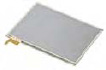 |
| Touch screen breakout |  |
Connect It Up
Connect everything as shown in Figure 12-1.

Figure 12-1. The circuit for Project 33 – Basic Touch Screen (see insert for color version)
The breakout unit has pins marked as X1, Y2, X2, and Y1. Connect the pins as described in Table 12-1.
Table 12-1. Pin Connections for Project 33
| Arduino | Breakout |
| Digital Pin 8 | X1 |
| Digital Pin 9 | Y2 |
| Digital Pin 10 | X2 |
| Digital Pin 11 | Y1 |
| Analog Pin 0 | Y1 |
| Analog Pin 1 | X2 |
You will need to solder some header pins to the breakout unit. The pins are soldered such that the Sparkfun logo is facing upward. The screen is connected to the breakout unit via the small connector. Pull back the tab and push the tiny ribbon cable into the connector, then push the tab closed to lock it in place. The screen goes with the ribbon connector at the top right when connecting. From now on, be very careful with the unit is it is very fragile and easily broken! I broke three screens and two breakouts in testing. If you can find a way of fixing the breadboard, breakout, and touch screen in place to prevent it from moving, you should do so.
Enter the Code
Enter the code in Listing 12-1.
Listing 12-1. Code for Project 33
// Project 33


// Power connections

#define Left 8     // Left (X1) to digital pin 8

#define Bottom 9   // Bottom (Y2) to digital pin 9

#define Right 10   // Right (X2) to digital pin 10

#define Top 11     // Top (Y1) to digital pin 11


// Analog connections

#define topInput 0   // Top (Y1) to analog pin 0

#define rightInput 1 // Right (X2) to analog pin 1


int coordX = 0, coordY = 0;


void setup()

{

        Serial.begin(38400);

}


void loop()
{

        if (touch())  // If screen touched, print co-ordinates

        {

                Serial.print(coordX);

                Serial.print("  ");

                Serial.println(coordY);

                delay(250);

        }

}
// return TRUE if touched, and set coordinates to touchX and touchY

boolean touch()

{

        boolean touch = false;


        // get horizontal co-ordinates
        pinMode(Left, OUTPUT);

        digitalWrite(Left, LOW); // Set Left to Gnd


        pinMode(Right, OUTPUT); // Set right to +5v
        digitalWrite(Right, HIGH);


        pinMode(Top, INPUT); // Top and Bottom to high impedance
        pinMode(Bottom, INPUT);


        delay(3);
        coordX = analogRead(topInput);


        // get vertical co-ordinates
        pinMode(Bottom, OUTPUT); // set Bottom to Gnd

        digitalWrite(Bottom, LOW);


        pinMode(Top, OUTPUT); // set Top to +5v
        digitalWrite(Top, HIGH);


        pinMode(Right, INPUT); // left and right to high impedance
        pinMode(Left, INPUT);


        delay(3);
        coordY = analogRead(rightInput);


        // if co-ordinates read are less than 1000 and greater than 0 then the screen

has been touched

        if(coordX < 1000 && coordX > 0 && coordY < 1000 && coordY > 0) {touch = true;}


          return touch;

}
Enter the code and upload it to your Arduino. Once it is running, open up the serial monitor, and then touch the touch screen. Whenever the screen is touched, the coordinates of your finger will be displayed on the serial monitor. The coordinates are X across the horizontal plane going from left to right and Y across the vertical plane going from top to bottom.
Before you take a look at the code, it will help if you know how a touch screen works. I will therefore take a look at the hardware before examining the code.
Project 33 – Basic Touch Screen – Hardware Overview
The touch screen that you are using, from a Nintendo DS, is known as a resistive touch screen. It is a relatively simple construction made up of different layers. The bottom layer of the screen is made of glass that has been coated with a transparent film of metal oxide. This makes the coating both conductive and resistive. A voltage applied across the film has a gradient. On top of the rigid glass layer is a flexible top layer that is also covered in the transparent resistive film. These two layers are separated by a very thin gap kept apart by a grid of tiny insulating dots. These dots have the job of holding the two conductive layers apart so they don’t touch.
If you examine your touch screen, you will see four connectors on the ribbon cable that lead to four metallic strips on the edges of the screen. Two of the metal strips are at the top and bottom of the screen, and if you flip the screen over, you will see the other two on the second layer and on the left and right hand sides of the screen.
When a finger or stylus is pressed against the top flexible layer, the layer bends down to touch the rigid layer, closing the circuit and creating a switch (see Figure 12-2).

Figure 12-2. How a touch screen works (courtesy of Mercury13 from Wikimedia Commons). 1: Rigid layer. 2: Metal oxide layer. 3: Insulating dots. 4: Flexible layer with metal oxide film.
To find the coordinates of the touched point, a voltage is first applied across the gradient from left to right. Making one side Ground and the other 5v accomplishes this. Then, one of the strips on the opposite layer is read using an analog input to measure the voltage. The voltage when a point is pressed close to the five volts side will measure close to five volts; likewise, the voltage when pressed close to the ground side will measure close to zero.
Next, the voltage is applied across the opposing layer and read from the other. This is done in quick succession hundreds of times a second so by reading first the X and then the Y axis quickly, you can obtain a voltage for each layer. This gives you an X and Y coordinate for the point on the screen that has been touched. If you touch two points on the screen at the same time, you get a reading equal to the halfway point in-between the two touched points.
There are other technologies used in touch screens, but the resistive type is cheap to manufacture and it’s very easy to interface to the Arduino without needing other circuitry to make it work. Now that you know how the screen works, let’s take a look at the code to see how to measure the voltages and obtain the coordinates.
Project 33 – Basic Touch Screen – Code Overview
The code for reading a touch screen is actually very simple. You start off by defining the four digital pins you will use for applying the power across the layers and the two analog pins you will use to measure the voltages:
// Power connections

#define Left 8     // Left (X1) to digital pin 8

#define Bottom 9   // Bottom (Y2) to digital pin 9

#define Right 10   // Right (X2) to digital pin 10

#define Top 11     // Top (Y1) to digital pin 11


// Analog connections

#define topInput 0   // Top (Y1) to analog pin 0

#define rightInput 1 // Right (X2) to analog pin 1
Then you declare and initialize the X and Y integers that will hold the coordinates, which are both initially set to zero:
int coordX = 0, coordY = 0;
As you are going to read the coordinates using the serial monitor, in the setup procedure all you need to do is begin serial communication and set the baud rate. In this case, you’ll use 38400 baud:
Serial.begin(38400);
The main program loop comprises nothing more than an if statement to determine of the screen has been touched or not:
if (touch()) // If screen touched, print co-ordinates
touch() is next. If the screen has been touched, you simply print out the X and Y coordinates to the serial monitor with a space in between, using the Serial.print commands:
Serial.print(coordX);

Serial.print("  ");

Serial.println(coordY);
After you have printed the coordinates, you wait a quarter of a second so the coordinates are readable if you keep your finger pressed down on the screen:
delay(250);
Next comes the function that does all of the hard work. The function will be returning a Boolean true or false, so it is of data type boolean. You do not pass any parameters to the function, so the parameter list is empty.
boolean touch()
You declare a variable of type boolean and initialise it to false. This will hold a true or false value depending if the screen is touched or not.
boolean touch = false;
Next, you need to put a voltage across the left-right layer and read the voltage using the top input pin on the second layer. To do this, you set the left and right pins to outputs and then make the left pin LOW so it becomes Ground and the right pin HIGH so it has five volts across it:
pinMode(Left, OUTPUT);

digitalWrite(Left, LOW); // Set Left to Gnd


pinMode(Right, OUTPUT); // Set right to +5v
digitalWrite(Right, HIGH);
The top and bottom digital pins are then set to INPUT so that they become high impedance:
pinMode(Top, INPUT);

pinMode(Bottom, INPUT);
High impedance simply means that the pins are not driven by the circuit and are therefore floating, i.e. they are neither HIGH nor LOW. You do not want these pins to have a voltage across them or to be at ground, hence the high impedance state is perfect as you will want to read an analog voltage using one of these pins.
Next, you wait a short delay to allow the above state changes to occur and then read the analog value from the top input pin. This value is then stored in coordX to give you the X coordinate.
delay(3);

coordX = analogRead(topInput);
You now have your X coordinate. So next you do exactly the same thing but this time you set the voltage across the top-bottom layer and read it using the rightInput pin on the opposing layer:
pinMode(Bottom, OUTPUT); // set Bottom to Gnd

digitalWrite(Bottom, LOW);


pinMode(Top, OUTPUT); // set Top to +5v
digitalWrite(Top, HIGH);


pinMode(Right, INPUT); // left and right to high impedance
pinMode(Left, INPUT);


delay(3);
coordY = analogRead(rightInput);
You set the Boolean variable touch to true only if the values read are greater than zero and less than one thousand. This is to ensure you only return a true value if the readings are within acceptable values.
if(coordX < 1000 && coordX > 0 && coordY < 1000 && coordY > 0) {touch = true;}
You will find the values range from approximately 100 at the lowest scale to around 900 at the top end. Finally, you return the value of touch, which will be false if the screen is not pressed and true if it is:
return touch;
As you can see, reading values from the touch screen is very simple and allows for all kinds of uses. You can put a picture or diagram behind the screen relating to buttons or other controls or overlay the screen onto an LCD display, as in the Nintendo DS, which will allow you to change the user interface below the screens as required.
You’ll now move onto a simple demonstration of this by printing out a keypad that can be placed underneath the touch screen and reading the appropriate values to work out which key has been pressed.