Project 16 – Using an L293D Motor Driver IC
In the previous project, you used a transistor to control the motor. In this project, you are going to use a very popular motor driver IC called an L293D. The advantage of using this chip is that you can control two motors at the same time, plus you can control their direction. The chip can also be used to control a stepper motor, as you will find out in Project 28. (You can also use a pin-for-pin compatible chip known as the SN754410, which has a higher current rating.) Notice anything missing from the parts list? Diodes, perhaps? Not to worry; the IC has its own internal diodes, so you do not need one for this project.
Parts Required
| DC Motor |  |
| L293D or SN754410 Motor Driver IC |
|
| 10KΩ Potentiometer |  |
| Toggle Switch |  |
| 10KΩ Resistor | |
| Heatsink |  |
Connect It Up
First, make sure your Arduino is powered off by unplugging it from the USB cable. Now, take the required parts and connect them as shown in Figure 5-3. Again, check the circuit thoroughly before powering it up. The L293D gets VERY hot when in use. Therefore, a heatsink is essential. Glue the heatsink to the top of the chip using a strong epoxy glue. The larger the heatsink, the better. Be warned that the temperature can get hot enough to melt the plastic on a breadboard or any wires touching it. Do not touch the heatsink as you may burn yourself. Do not leave the circuit powered up and unattended in case it overheats. It may be prudent to use stripboard instead of a breadboard for this project to save damaging your breadboard due to heat.
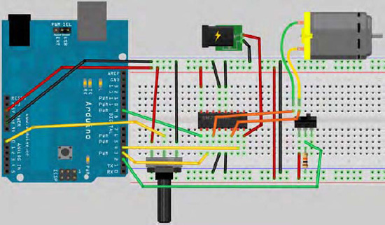
Figure 5-3. The circuit for Project 16 (see insert for color version)
Enter the Code
Once you are satisfied that your circuit is connected correctly, upload the code in Listing 5-2. Do not connect the external power supply at this stage.
Listing 5-2. Code for Project 16
// Project 16 - Using an L293D Motor Driver IC

#define switchPin 2 // switch input

#define motorPin1 3 // L293D Input 1

#define motorPin2 4 // L293D Input 2

#define speedPin 9 // L293D enable Pin 1

#define potPin 0 // Potentiometer on Analog Pin 0

int Mspeed = 0;  // a variable to hold the current speed value
void setup() {

//set switch pin as INPUT

pinMode(switchPin, INPUT);


// set remaining pins as outputs

pinMode(motorPin1, OUTPUT);

pinMode(motorPin2, OUTPUT);

pinMode(speedPin, OUTPUT);

}


void loop() {

  Mspeed = analogRead(potPin)/4; // read the speed value from the potentiometer

  analogWrite(speedPin, Mspeed); // write speed to Enable 1 pin

  if (digitalRead(switchPin)) { // If the switch is HIGH, rotate motor clockwise

    digitalWrite(motorPin1, LOW); // set Input 1 of the L293D low

    digitalWrite(motorPin2, HIGH); // set Input 2 of the L293D high

  }

  else {  // if the switch is LOW, rotate motor anti-clockwise

    digitalWrite(motorPin1, HIGH); // set Input 1 of the L293D low

    digitalWrite(motorPin2, LOW); // set Input 2 of the L293D high

  }

}
Once the code has finished uploading, set the potentiometer at its midpoint and plug in the external power supply. The motor will now rotate; you can adjust its speed by turning the potentiometer. To change direction of the motor, first set the speed to minimum, then flick the toggle switch. The motor will now rotate in the opposite direction. Again, be careful of that chip as it will get very hot once powered up.
Project 16 – Using an L293D Motor Driver IC – Code Overview
The code for this project is very simple. First, you define the pins you are going to put to use on the Arduino:
#define switchPin 2 // switch input

#define motorPin1 3 // L293D Input 1

#define motorPin2 4 // L293D Input 2

#define speedPin 9 // L293D enable Pin 1

#define potPin 0 // Potentiometer on Analog Pin 0
Then, set an integer to hold the speed value read from the potentiometer:
int Mspeed = 0; // a variable to hold the current speed value
In the setup function, you then set the appropriate pins to either inputs or outputs:
pinMode(switchPin, INPUT);


pinMode(motorPin1, OUTPUT);
pinMode(motorPin2, OUTPUT);

pinMode(speedPin, OUTPUT);
In the main loop, you first read in the value from the potentiometer connected to Analog Pin 0 and store it in Mspeed:
Mspeed = analogRead(potPin)/4; // read the speed value from the potentiometer
Then you set the PWM value on PWM Pin 9 to the appropriate speed:
analogWrite (speedPin, Mspeed); // write speed to Enable 1 pin
Then you have an if statement to decide if the value read in from the switch pin is either HIGH or LOW. If it is HIGH, then output 1 on the L293D is set to LOW and output 2 is set to HIGH. This will be the same as output 2 having a positive voltage and output 1 being ground, causing the motor to rotate in one direction:
if (digitalRead(switchPin)) { // If the switch is HIGH, rotate motor clockwise

    digitalWrite(motorPin1, LOW); // set Input 1 of the L293D low

    digitalWrite(motorPin2, HIGH); // set Input 2 of the L293D high

  }
If the switch pin is LOW, then output 1 is set to HIGH and output 2 is set to LOW, reversing the direction of the motor:
  else {  // if the switch is LOW, rotate motor anti-clockwise

    digitalWrite(motorPin1, HIGH); // set Input 1 of the L293D low

    digitalWrite(motorPin2, LOW); // set Input 2 of the L293D high

  }
The loop will repeat, checking for a new speed value or a new direction and setting the appropriate speed and direction pins. As you can see, using the motor driver IC is not at all as daunting as you might have thought at first. In fact, it has made your life a lot easier. Trying to recreate the above circuit and code without it would have been far more complex. Never be intimidated by ICs! A slow and careful read of their datasheets will reveal their secrets. Let's see how the new component introduced in this project works.
Project 16 – Using an L293D Motor Driver IC – Hardware Overview
The new component in Project 16 is the Motor Driver IC. This will be either the L293D or the SN754410, depending on what you have chosen (there are other chips available and a little research on the internet will find other pin compatible motor drivers).
The L293D is what is known as a Dual H-Bridge. A H-Bridge is a useful but simple electronic concept (see Figure 5-4).
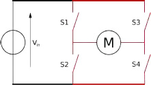
Figure 5-4. A H-Bridge made of switches (image by Cyril Buttay)
In Figure 5-4, a motor is connected to four switches. The configuration is called a H-Bridge as it resembles a letter H with the load bridge the centre. Now take a look at Figure 5-5.

Figure 5-5. Changing motor direction on the H-Bridge (image by Cyril Buttay)
On the left hand side, the top left and the bottom right switches are closed. By doing so, the current will flow across the motor from left to right and the motor will rotate. If you open those switches and close the top right and bottom left switches instead, the current will flow across the motor in the opposite direction and hence cause it to rotate in the opposite direction. This is how an H-Bridge works.
The Motor driver IC is made up of two H-Bridges. Instead of switches, it uses transistors. In the same way that the transistor in Project 15 was used as a switch, the transistors inside the H-Bridge switch on and off in the same configuration as Figure 5-5 to make your motor rotate in either direction. The chip is a Dual H-Bridge because it has two H-Bridges inside it. Thus you are able to control two motors and their directions at the same time.
Note that you could make your own H-Bridge out of transistors and diodes, and it would do the same job as the L293D. The L293D has the advantage of being tiny and having all those transistors and diodes packaged up inside a small space.
EXERCISE
Now try out the following exercise.
Exercise 1: Instead of just one motor, try connecting up two, with two direction switches and potentiometers to control the direction and speed. Figure 5-6 shows the pinouts of the chip.
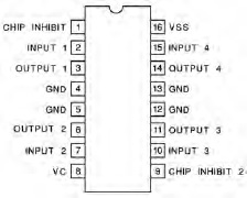
Figure 5-6. The pinouts for the L293D (or SN754410)