Project 25 – Servo Control
In this very simple project you will control a single servo using a potentiometer.
Parts Required
You will need to obtain a standard RC servo; any of the small or mid-sized servos will do. Larger servos are not recommended because they require their own power supply as they consume a lot of current. Also, you'll need a potentiometer; pretty much any value rotary potentiometer will do. I used a 4.7K ohm one for testing. Note that you may also wish to connect your Arduino to an external DC power supply.
| Standard RC Servo |  |
| Rotary Potentiometer | 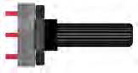 |
Connect It Up
The circuit for Project 25 is extremely simple. Connect it as shown in Figure 9-3.
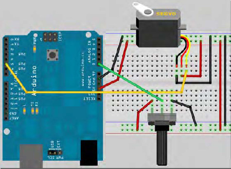
Figure 9-3. The circuit for Project 25 – Servo Control (see insert for color version)
The servo has three wires coming from it. One will be red and will go to +5v. One will be black or brown and will go to Ground. The third will be white, yellow, or orange and will be connected to Digital Pin 5.
The rotary potentiometer has the outer pins connected to +5v and Ground and the middle pin to Analog Pin 0.
Once you are happy everything is connected as it should be, enter the code below.
Enter The Code
And now for one of the shortest programs in the book, see Listing 9-1!
Listing 9-1. Code for Project 25
// Project 25

#include <Servo.h>


Servo servo1;  // Create a servo object
void setup()

{

        servo1.attach(5);  // Attaches the servo on Pin 5 to the servo object

}


void loop()

{

        int angle = analogRead(0); // Read the pot value

        angle=map(angle, 0, 1023, 0, 180); // Map the values from 0 to 180 degrees

        servo1.write(angle); // Write the angle to the servo

        delay(15); // Delay of 15ms to allow servo to reach position

}
Project 25 – Servo Control – Code Overview
First, the Servo.h library is included:
#include <Servo.h>
Then a Servo object called servo1 is declared:
Servo servo1; // Create a servo object
In the setup loop, you attach the servo you have just created to Pin 5:
servo1.attach(5); // Attaches the servo on Pin 5 to the servo object
The attach command attaches a created servo object to a designated pin. The attach command can take either one parameter, as in your case, or three parameters. If three parameters are used, the first parameter is the pin, the second is the minimum (0 degree) angle in pulse width in microseconds (defaults to 544), and the third parameter is the maximum degree angle (180 degrees) in pulse width in microseconds (defaults to 2400). This will be explained in the hardware overview. For most purposes you can simply set the pin and ignore the optional second and third parameters.
You can connect up to 12 servos to an Arduino Duemilanove (or equivalent) and up to 48 on the Arduino Mega—perfect for robotic control applications!
Note that using this library disables the analogWrite (PWM) function on Pins 9 and 10. On the Mega you can have up to 12 motors without interfering with the PWM functions. The use of between 12 and 23 motors will disable the PWM functionality on Pins 11 and 12.
In the main loop, read the analog value from the potentiometer connected to Analog Pin 0:
int angle = analogRead(0); // Read the pot value
Then that value is mapped so the range is now between 0 and 180, which will correspond to the degree angle of the servo arm:
angle=map(angle, 0, 1023, 0, 180); // Map the values from 0 to 180 degrees
Then you take your servo object and write the appropriate angle, in degrees, to it (the angle must be between 0 and 180 degrees):
Finally, a delay of 15ms is programmed to allow the servo time to move into position:
delay(15); // Delay of 15ms to allow servo to reach position
You can also detach() a servo from a pin, which will disable it and allow the pin to be used for something else. Also, you can read() the current angle from the servo (this is the last value passed to the write() command).
You can read more about the Servo library on the Arduino website at http://arduino.cc/en/Reference/Servo.
Project 25 – Servo Control – Hardware Overview
A servo is a little box that contains a DC electric motor, a set of gears between the motor and an output shaft, a position sensing mechanism, and the control circuit. The position sensing mechanism feeds back the servo's position to the control circuitry, which uses the motor to adjust the servo arm to the position that the servo should be at.
Servos come in many sizes, speeds, strengths, and precisions. Some of them can be quite expensive. The more powerful or precise the servo is, the higher the price. Servos are most commonly used in radio controlled aircraft, cars, and boats.
The servo's position is controlled by providing a set of pulses. This is PWM, which you have come across before. The width of the pulses is measured in milliseconds. The rate at which the pulses are sent isn't particularly important; it's the width of the pulse that matters to the control circuit. Typical pulse rates are between 400Hz and 50Hz.
On a standard servo the center position is reached by providing pulses at 1.5 millisecond intervals, the -45 degree position by providing 0.6 millisecond pulses, and the +45 degree position by providing 2.4 millisecond pulses. You will need to read the datasheet for your servo to find the pulse widths required for the different angles. However, you are using the Servo.h library for this project, so you don't need to worry: the library provides the required PWM signal to the servo. Whenever you send a different angle value to the servo object, the code in the library takes care of sending the correct PWM signal to the servo.
Some servos provide continuous rotation. Alternatively, you can modify a standard servo relatively easily to provide continuous rotation.

Figure 9-4. Modifying a servo to provide continuous rotation (image by Adam Grieg)
A continuous rotation servo is controlled in the same way, by providing an angle between 0 and 180 degrees. However, a value of 0 will provide rotation at full speed in one direction, a value of 90 will be stationary, and a value of 180 will provide rotation at full speed in the opposite direction. Values in-between these will make the servo rotate in one direction or the other and at different speeds. Continuous rotation servos are great for building small robots (see Figure 9-4). They can be connected to wheels to provide precise speed and direction control of each wheel.
There is another kind of servo known as a linear actuator that rotates a shaft to a desired position allowing you to push and pull items connected to the end of the shaft. These are used a lot in the TV program “Mythbusters” by their resident robotics expert, Grant Imahara.