Project 30 – Line Following Robot
Now that you know how to control the two motors or your robot base using a motor shield, you are going to put those skills to good use! In this project, you are going to build a robot that is capable of detecting and following a black line drawn on a floor. This kind of robot is still used today in factories to ensure the robot keeps to a set path across the factory floor. They are known as Automated Guided Vehicles (AGVs).
Parts Required
For this project, you will need a small lightweight robot base. These can be purchased ready-made or in kit form. Or you can build one from scratch (much more fun). Make sure the wheels are geared so that they rotate much slower than the motor because the robot must be able to move fairly slowly to enable it to navigate the line.
As the robot will be autonomous, it will need its own battery pack. I found that a six-AA battery holder provided enough power for the Arduino, sensors, LEDs, shield, and motors. Larger batteries will give you a longer life but at the expense of greater weight, so it will depend on the load bearing capacity of your robot.
| Motor Shield |  |
| 4 × Current Limiting Resistors | |
| 3 × 1KΩ Resistors | |
| 4 × White LEDs | |
| 3 × Light Dependent Resistors | |
| 2 × DC Motors or… | |
| .... a 2 wheeled robot base |  |
| Battery pack |  |
Connect It Up
Connect the circuit up as in Figure 10-9. The shield is not shown, but the four outputs simply go to Motor A and Motor B.
The four LEDs can be any color as long as they have a reasonable enough brightness to illuminate the floor and create contrast between the floor and the black line for your sensor to detect. White LEDs are best as they output the greatest brightness for the lowest current. Four of these are connected in parallel with Pin 9. Make sure that you use the appropriate current limiting resistors for your LEDs.
Finally, connect up three light dependent resistors to Analog Pins 0, 1, and 2. One side of the LDR goes to ground, the other to +5v via a 1K ohm resistor. The wire from the analog pins goes between the resistor and the LDR pin (you used LDRs in Project 14).
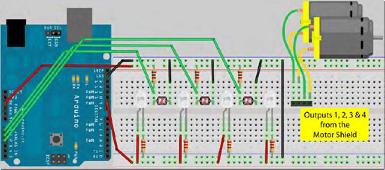
Figure 10-9. The circuit for Project 30 – Line Following Robot (see insert for color version)
The breadboard above can be used for testing purposes. However, for making the robot you will need to make up a sensor bar that houses the four LEDs and the three LDRs. These must be positioned so that they are all close together and pointing in the same direction. I soldered up the LED and sensor circuit onto a small piece of stripboard and placed the three LDRs in-between the four LEDs and just slightly higher than the LEDs so that the light from them did not shine onto the sensor. Figure 10-10 shows how I did it.
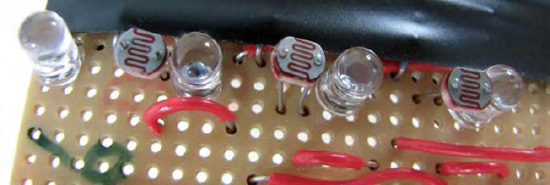
Figure 10-10. The sensor bar consisting of four LEDs and three LDRs.
The sensor bar is then attached to the front side of your robot in such a way that the LEDs and LDRs are about 1cm or half an inch above the floor (see Figure 10-11). I simply taped mine to the front of my robot, but for a more permanent solution the sensor bar could be bolted to the chassis.
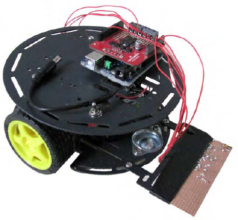
Figure 10-11. The robot base fitted with the sensor bar.
The battery pack should be placed centrally inside the robot base so as to not upset the load balance between the wheels. Fix the pack to the chassis with some Velcro so it cannot move around as the robot navigates the course.
As you can see from Figure 10-11, wires runs between the motor shield and the two motors and also down to the sensor bar. One wire provides +5v, one is for Ground, one is for +5v from Digital Pin 9, and the other three go to analog sensors 0, 1 and 2, with 0 being the left hand sensor (looking from the front of the robot), 1 being the center sensor, and 2 being the right hand one. It is critical that you get the order correct or the robot will not work as expected. See Figure 10-12 for an image of my robot in action on my kitchen floor (there is also a video of it in action on YouTube and Vimeo if you can find them).
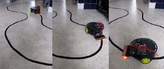
Figure 10-12. My own line-following robot in action.
Enter the Code
When you have built your robot and everything has been checked over, enter the code from Listing 10-3.
Listing 10-3. Code for Project 30
// Project 30 - Line Following Robot


#define lights 9
int LDR1, LDR2, LDR3; // sensor values


// calibration offsets
int leftOffset = 0, rightOffset = 0, centre = 0;

// pins for motor speed and direction

int speed1 = 3, speed2 = 11, direction1 = 12, direction2 = 13;

// starting speed and rotation offset

int startSpeed = 70, rotate = 30;

// sensor threshold

int threshhold = 5;

// initial speeds of left and right motors

int left = startSpeed, right = startSpeed;


// Sensor calibration routine
void calibrate() {


  for (int x=0; x<10; x++) { // run this 10 times to obtain average
  digitalWrite(lights, HIGH); // lights on

  delay(100);

  LDR1 = analogRead(0); // read the 3 sensors

  LDR2 = analogRead(1);

  LDR3 = analogRead(2);
leftOffset = leftOffset + LDR1; // add value of left sensor to total

  centre = centre + LDR2; // add value of centre sensor to total

  rightOffset = rightOffset + LDR3; // add value of right sensor to total


  delay(100);

  digitalWrite(lights, LOW); // lights off

  delay(100);

  }

  // obtain average for each sensor

  leftOffset = leftOffset / 10;

  rightOffset = rightOffset / 10;

  centre = centre /10;

  // calculate offsets for left and right sensors

  leftOffset = centre - leftOffset;

  rightOffset = centre - rightOffset;

}


void setup()
{

    // set the motor pins to outputs

    pinMode(lights, OUTPUT); // lights

    pinMode(speed1, OUTPUT);

    pinMode(speed2, OUTPUT);

    pinMode(direction1, OUTPUT);

    pinMode(direction2, OUTPUT);

    // calibrate the sensors

    calibrate();

    delay(3000);


    digitalWrite(lights, HIGH); // lights on

    delay(100);


    // set motor direction to forward

    digitalWrite(direction1, HIGH);

    digitalWrite(direction2, HIGH);

    // set speed of both motors

    analogWrite(speed1,left);

    analogWrite(speed2,right);

}


void loop() {


  // make both motors same speed

  left = startSpeed;

  right = startSpeed;


  // read the sensors and add the offsets
  LDR1 = analogRead(0) + leftOffset;

  LDR2 = analogRead(1);

  LDR3 = analogRead(2) + rightOffset;
// if LDR1 is greater than the centre sensor + threshold turn right

  if (LDR1 > (LDR2+threshhold)) {

    left = startSpeed + rotate;

    right = startSpeed - rotate;

  }


  // if LDR3 is greater than the centre sensor + threshold turn left

  if (LDR3 > (LDR2+threshhold)) {

    left = startSpeed - rotate;

    right = startSpeed + rotate;

  }


  // send the speed values to the motors

    analogWrite(speed1,left);

    analogWrite(speed2,right);

}
Lay out a course for your robot on a flat surface. I used the linoleum on my kitchen floor and made a course using black electrical tape. Turn the robot on, making sure it is sitting on a blank piece of floor next to, but not over, the back line. The calibration routine will run, making the LEDs flash ten times in quick succession. Once this stops, you have three seconds to pick up the robot and place it on the line. If all is well, the robot will now happily follow the line. Don't make the turns too sharp as this rapid transition will not be detected with only three LDRs. See Figure 10-12 for an example of a course made with black electrical tape.
Project 30 – Line Following Robot – Code Overview
First, you define the pin for the lights, and then three integers are declared that will hold the values read from the three light dependent resistors:
#define lights 9

int LDR1, LDR2, LDR3; // sensor values
Then another three integers are declared that will hold the offset values for the three sensors calculated in the calibration routine (this will be explained later):
int leftOffset = 0, rightOffset = 0, centre = 0;
Next, you define the pins that will control the speed and direction of the two motors:
int speed1 = 3, speed2 = 11, direction1 = 12, direction2 = 13;
Then two integers are created to hold the initial speed of the motors and the speed offset for each wheel that you add or subtract to make the robot rotate:
int startSpeed = 70, rotate = 30;
The default speed is set to 70, which is around 27% duty cycle. You may need to adjust this value to suit your own robot. Too high a value will make the robot overshoot the line and too low will prevent the motors from turning fast enough to turn the wheels to overcome friction.
The rotate value is how much you will speed up or slow down the wheels to cause the robot to turn. In my case, the required value is 30. So when turning left, for example, the right wheel spins at speed 100 and the left wheel at a speed of 40 (70+30 and 70-30). The rotate value is another setting you may need to adjust for your own setup.
Another integer is created to hold the sensor threshold:
int threshhold = 5;
This is the difference in values required between the center sensor and the left or right sensors before the robot decides to turn. In my case, a setting of 5 works well. This means that the left and right sensors would need to detect a value greater than the value read from the center sensor plus the threshold value before action is taken. In other words, if the center sensor is reading a value of 600 and the left sensor is reading 603, then the robot will keep going straight. However, a left sensor value of 612 (which is higher than the center value plus threshold) means that the left sensor is detecting the back line, indicating that the robot is too far over to the left. So the motors would adjust to make the robot turn to the right to compensate.
The threshold value will vary depending on the contrast between your floor (or whatever surface you use) and the black line. This may need to be adjusted to ensure the robot only turns when it has detected enough of a difference between floor and line to ascertain it had moved too far left or right.
The final set of variables will store the speed values for the left and right motors. These are initially set to the value in startSpeed:
int left = startSpeed, right = startSpeed;
After the variables are all declared and initialized, you come to your first and only function, which is the calibration routine:
void calibrate() {
The purpose of this routine is two-fold. First, it obtains an average value from each of the three sensors over a sequence of ten reads. Second, it flashes the lights 10 times (while reading values from the three sensors) to show you that the robot is calibrating and nearly ready to run.
The sensors require calibration, as each one will read different values to the next one. Every LDR will give a slightly different reading and this will be affected by manufacturing tolerances, the tolerance of the voltage divider resistors used, and the resistance in the wires. You want all three sensors to read (roughly) the same value, so you take ten readings from each, average them out, and calculate the difference that the left and right sensors are from the center sensor (which is used as the baseline).
You start off with creating a for loop that runs ten times:
for (int x=0; x<10; x++) {
The LEDs attached to Pin 9 are turned on, followed by a delay of 100 milliseconds:
digitalWrite(9, HIGH);

delay(100);
Next, the values from all three sensors are read in and stored in LDR1, LDR2, and LDR3:
LDR1 = analogRead(0);

LDR2 = analogRead(1);

LDR3 = analogRead(2);
Now you take those values and add them to the leftOffset, center, and rightOffset variables. These variables start off at zero, so after ten iterations they will contain a running total of all ten values read from the sensors.
leftOffset = leftOffset + LDR1;

centre = centre + LDR2;

rightOffset = rightOffset + LDR3;
Then you wait 100 milliseconds, turn the light off, wait another 100 milliseconds, and then repeat the process:
delay(100);

digitalWrite(9, LOW); // lights off

delay(100);
After this process has repeated ten times, you exit the for loop and then divide each of the running totals by ten. This gives you an average sensor reading for each of the three LDRs.
leftOffset = leftOffset / 10;

rightOffset = rightOffset / 10;

centre = centre /10;
You then calculate what the offset will be by deducting the left and right sensor values by the centre one:
leftOffset = centre - leftOffset;

rightOffset = centre - rightOffset;
These values will be added to the sensor readings from the left and right sensors so that all three sensors will be giving approximately the same readings. This will make ascertaining the difference between the three readings a lot easier when detecting the difference between the floor and the black line.
Next, you have the setup routine, which starts off by setting the pin for the LEDs and the pins for the motor speed and direction to OUTPUT:
pinMode(9, OUTPUT); // lights

pinMode(speed1, OUTPUT);

pinMode(speed2, OUTPUT);

pinMode(direction1, OUTPUT);

pinMode(direction2, OUTPUT);
The calibration routine is now run to ensure all three sensors issue similar readings, followed by a delay of three seconds. After the LEDs flash ten times during the calibration routine, you have three seconds to place the robot on the line it is to follow:
calibrate();

delay(3000);
The lights are turned on, followed by a brief delay:
digitalWrite(9, HIGH); // lights on

delay(100);
The direction of both motors is set to forward and the speeds are set to the values stored in the right and left variables (initially set to the value stored in startSpeed):
digitalWrite(direction1, HIGH);

digitalWrite(direction2, HIGH);

analogWrite(speed1,left);

analogWrite(speed2,right);
Now you move onto the main loop of the program. This starts off by setting the speed of the left and right motors to the value in startSpeed:
left = startSpeed;

right = startSpeed;
The motor speed is reset to these values at the start of each loop so that the robot is always going forward, unless the values are changed later in the loop to make the robot turn.
You now read the sensor values from each of the three LDRs and store the values in the LDR1, LDR2, and LDR3 integers. The offsets calculated for the left and right sensors are added to the value so that when all three sensors are looking at the same surface they will read approximately the same values.
LDR1 = analogRead(0) + leftOffset;

LDR2 = analogRead(1);

LDR3 = analogRead(2) + rightOffset;
Now you need to check those sensor values and see if the black line has moved to far from the center. You do this by checking the left and right sensors and seeing if the values read are greater than the value read from the center LDR plus the threshold offset.
If the value from the left sensor is greater than the reading-plus-threshold-offset, then the black line has shifted from the centerline and is too far to the right. The motor speeds are then adjusted so that the left wheel spins faster than the right, thus turning the robot to the right which will bring the black line back to the centre.
if (LDR1 > (LDR2+threshhold)) {

    left = startSpeed + rotate;

    right = startSpeed - rotate;

  }
The same is done for the right hand sensor, this time turning the robot to the left:
  if (LDR3 > (LDR2+threshhold)) {

    left = startSpeed - rotate;

    right = startSpeed + rotate;

  }
The speeds, which may or may not have been adjusted if the line was off center, are then sent out to the motors:
analogWrite(speed1,left);

analogWrite(speed2,right);
This whole process is repeated over and over many times per second and forms a feedback loop which makes the robot follow the line.
If your robot runs off the line, you may need to adjust the speed in startSpeed to a slower one. If it doesn't turn fast or far enough or if it turns too much, then the rotate value needs to be adjusted accordingly. The sensitivity of the LDRs can be adjusted by changing the value in the threshold variable. Play around with these values until you get the robot to follow the line successfully.