In the previous recipe, we created three different types of shape keys. Besides the fixing shape keys, that have a fixed value (no pun intended), we now need a way to set the amount of influence of the other two types of shape keys, facial expressions, and the muscle movements during the animation. This is accomplished by setting drivers, though with different kinds of controls.
Start from the previously saved Gidiosaurus_shapekeys.blend file:
- Go to the Outliner and hide the Armor object.
- Select the Armature rig, switch to the Octahedral bones draw mode, and press Tab to enter Edit Mode; zoom to the character head and add six bones located as follows: two bones close to both the right and the left eyebrows, two bones close to both the sides of the grin snout area, and two bones close to the nostrils. Enable the Names item in the Skeleton subpanel under the Object Data window and rename the bones accordingly and with the correct .L or .R suffix, then be sure to have them located on the first bone layer by pressing the M key to call the Change Bone Layers pop-up.
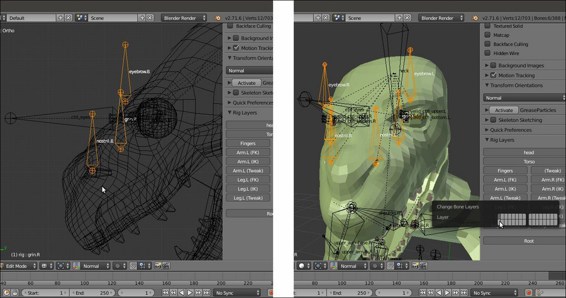
The new bones for the shape key drivers
- Exit Edit Mode and select the Gidiosaurus mesh.
- Go to the Shape Keys subpanel under the Object Data window and expand the list window by left-clicking on the = icon at the bottom and dragging it downward.
- Now right-click on the value (0.000) at the right side of the name of the first shape key (grin.L) and from the pop-up panel, select the Add Driver item; the value is enhanced, in violet, to show that now it has a driver associated.
- Repeat the same for all the shape keys in the list except for the prop one, which has a fixed value of 1.000:
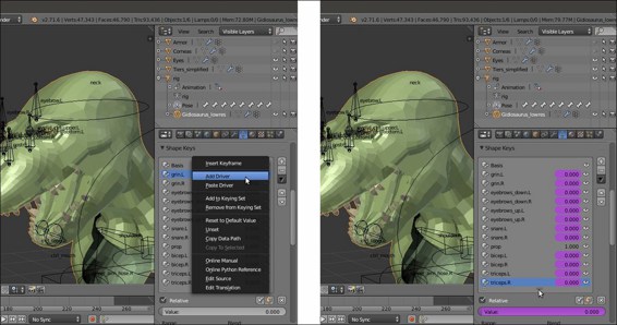
The shape keys list showing they have drivers
- Split the 3D viewport horizontally into two parts, change the upper part into a Graph Editor window, or simply switch the screen to the Animation layer (in the two files provided with the cookbook, there are actually two prepared animation screens, Animation1 and Animation2). Click on the Editing context being displayed button in the toolbar of the Graph Editor window and change it from F-Curves to Drivers.
Let's start with the expressions shape keys:
- If not already present, press the N key to open the Properties sidepanel of the Graph Editor window, then click on the Value (grin.L) top item in the drivers list at the top-left of the screen:
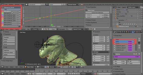
The Graph Editor window, at the top of the screen, with the driver f-curve
- Go to the Properties panel of the Graph Editor and, by scrolling down, find the Drivers subpanel. In the Driver Type slot, switch from the Scripted Expression item to the Averaged Value one.
- In the Ob/Bone slot, select rig and in the under slot (Name of PoseBone to use as target), select the grin.L bone.
- Going downward, in the Variable Type slot, select the Y Location item and in Space, select Local Space.
- Click on the Update Dependencies button at the top of the Drivers subpanel (the Update Dependencies function works particularly for Scripted Expression; it is quite important to use it to refresh the new setups each time).
- Go even further down and click on the Add Modifier button in the Modifier subpanel; from the Add F-Curve Modifier pop-up menu, select the Generator item.
- In the Coefficient for polynomial – x slot, change the value 1.000 to the value 20.000 (this is to re-map the declivity of the f-curve and therefore the speed of the corresponding shape key):
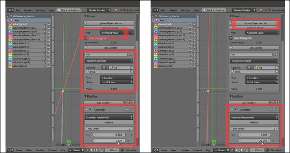
The N Properties Graph Editor sidepanel for the selected driver
- Now select the grin.L bone and in Pose Mode, move it upward to see the grin.L shape keys being animated on the character's snout.
- Go to the Shape Keys subpanel and right-click on the value to the right side of the grin.L shape; from the pop-up menu, select the Copy Driver item.
- Select the grin.R shape key and right-click on the value to the right; from the pop-up menu, select the Paste Driver item.
- Go to the Animation screen and switch the grin.L to the grin.R bone in the Ob/Bone field under the Drivers subpanel.
- Copy and paste the drivers for the eyebrows_up.L and eyebrows_up.R shape keys, then replace the driver bones names in the Ob/Bone field under the Drivers subpanel.
- Go to the Shape Keys subpanel under the Object Data window and set the Max value under the Range item to 0.600 for both the eyebrows_up.L and eyebrows_up.R shape keys; this is to limit the movement of the shape keys to avoid any intersection with the character's helm.
- Copy and paste the drivers for the eyebrows_down.L and eyebrows_down.R shape keys. This time, leave the same driver bone names and instead change the value of the Coefficient for polynomial – x to negative and -20.000 to invert the direction of the f-curve.
- Repeat the procedure for the snare.L and snare.R shape keys, this time switching the Variable Type from Y Location to X Location and assigning a negative -20.000 value to the snare.L driver and a positive 20.000 value to the snare.R one.
At this point, all that is left is to assign automatic drivers for the shape keys to stretch and grow muscles we created for the character's arms.
- Click on the Value (bicep.L) item in the drivers window at the left top of the Graph Editor and then go to the Properties panel on the right and then to the Drivers subpanel. In the Driver Type slot, select the Averaged Value item again; in the Variable Type slot, switch to Rotational Difference.
- In the Bone1 slot, select rig and in the slot below (Name of PoseBone to use as target), select the DEF-forearm.01.L bone; in the Bone2 slot, select rig again, and then DEF-upperarm.02.L.
- In the Graph Editor, click on a point of the f-curve to select it and then press the L key to select all the points of the f-curve; move them downward, on the y axis, by -1.400 (G | Y | -1.4 | Enter).
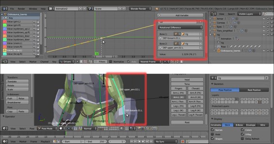
The triceps Rotational Difference driver
- Copy and paste the driver to the bicep.R shape key, then change the .L suffixes of the bones to the .R ones.
- Copy the bicep.L driver and paste it to the triceps.L shape key; click on the Add Modifier button under the Modifier subpanel; and from the Add F-Curve Modifier pop-up menu, select the Generator item.
- In the Coefficient for polynomial – y slot, write the value 2.300 and in the x slot, write the value -1.000 (remember that all these values in the recipe are not universal and are valid just for this Gidiosaurus model in this particular setup; the drivers values could change from character to character, so always test them on your model).
- Copy and paste to the triceps.R shape key, and change the suffixes of the bones.
- Click on the Update Dependencies button at the top of the Drivers subpanel and save the file.
Drivers assigned to bones as controllers for the shape keys are not only an effective way to create a device for animation but also a mandatory technique in the Blender pipeline workflow, where a character is usually linked into the scene from a different file and the rig gets proxified (we'll see how to do this in the next chapter). The only possible way to have access to the shape keys in a linked character is through the drivers and the rig.
As you probably already know, shape keys are often used not only for facial expressions but also to mimic the stretching and the growing of the body's muscles according to the movement of a character's limbs. In this case, their influence is automatically driven by the rotation of the respective bones through the Rotational Difference drivers that, as the name itself says, base their influence on the difference of rotation between two bones; more precisely, on the angle between them.
The Generator modifier we added is a multiplier we used to virtually modify the slope inclination of the f-curves of the drivers. The default inclination of the f-curve wasn't enough to fully map the curve itself to a driver bone movement of (almost) just one or two Blender Units (it was too slow, resulting in a required driver movement of several units to have an appreciable effect), so we increased the declivity by a factor of 20.000 to have a faster correspondence.
However, the same modifier was also used to reverse the direction of the f-curve, by using a negative value of -20.000, for example to drive the downward movement of the eyebrows, or to change the location of the curve along the y axis so as to tweak the timing of the driver influence, like in the triceps shape keys.
Therefore, by copying and pasting a driver and giving an opposite declivity at the slope of the copied one, it is possible to drive two opposite shape keys through the same bone, as for the eyebrows shape keys:
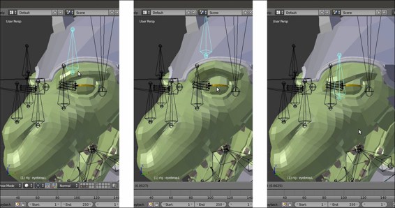
The same bone moving in two opposite directions to drive two opposite shape keys
To add shape keys and the respective drivers to the Gidiosaurus model, we used the Gidiosaurus_skinning_rigify.blend file, with the rig created by the Rigify addon. The control bones of a Rigify rig have pre-made Custom Shapes to make their identification and selection easier and are usually located in the last scene layer.
So, for the last step, I just modeled a new simple custom shape, a small Circle mesh with 16 vertices. I named it Widget_generic4 and I assigned it to all the driver bones:
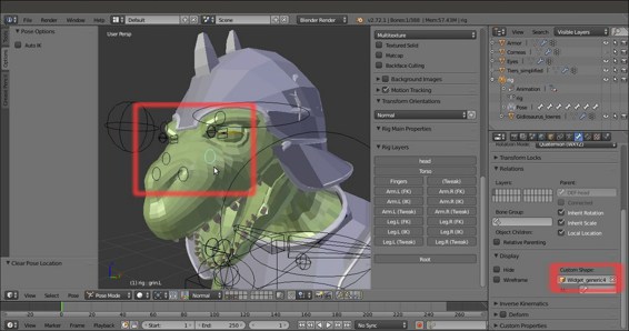
The driver bones with the new Custom Shape
