Chapter 3
Components and Hacking/Modifying Parts for Radio Circuits
This chapter will present some of the basic components or parts needed for building radios. These components include variable capacitors, antenna coils, and transformers. Other parts that will be used in the projects include transistors, diodes, capacitors, and inductors.
Antenna Coils
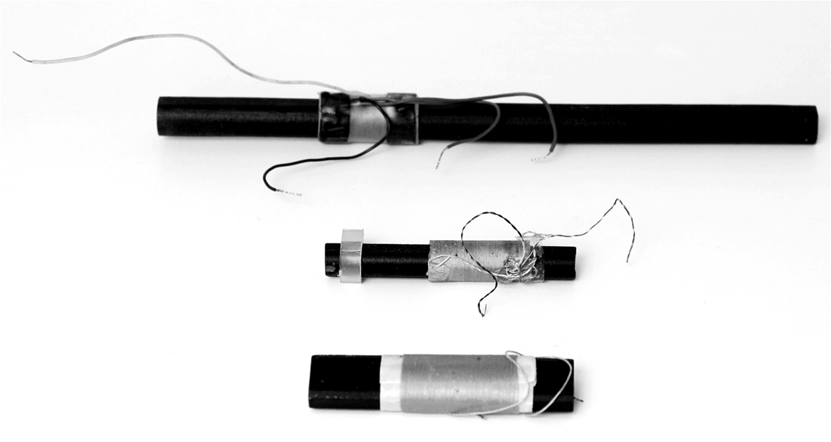
Basically, the antenna coils that will be used in this book are the ferrite rod or ferrite bar types (Figure 3-1). These types of antenna coils are used commonly in all portable amplitude-modulated (AM) broadcast radios. They are small in size but receive radio-frequency (RF) signals equivalently in strength to the older, large air-core-loop antennas.
The antenna coil at the top of the figure is much longer than the other two, which allows for more sensitivity. That is, given the same RF signal, the longer rod antenna coil will yield more signal at its coil winding. This coil also has a secondary winding, which is “stepped” down by 10- to 20-fold to load into low-impedance transistor amplifiers. The primary winding of this antenna coil is normally connected to a tuning capacitor (variable capacitor). The primary winding inductance was measured at 430 μH, which matches with a variable capacitor of about 180 pF to 200 pF.
In the center of the figure is an antenna coil that is more miniaturized and will have less sensitivity to the antenna coil at the top of the figure. However, its primary winding inductance is actually higher at about 640 μH, which matches to a (more commonly available) 140-pF variable capacitor. This antenna coil also has a secondary winding that is stepped down.
Finally, the bar antenna coil at the bottom of the figure has an inductance of about 740 μH. At 740 μH of inductance, this is a bit higher than needed, and some portion of the winding will have to be removed for use with standard 140-pF, 180-pF, 270-pF, or 365-pF variable capacitors.
It should be noted that all three antenna coils in Figure 3-1 allow changing the inductance further by sliding the coil to different locations on the ferrite rod or bar. For example, to increase inductance, slide the coil to the middle, and to decrease inductance, slide the coil toward either end of the rod or bar.
FIGURE 3-1 Ferrite-bar/rod antenna coils.
Ferrite antenna coils are readily available on the Web such as on eBay. An alternative to making an antenna coil is to buy ferrite rods or bars and wind your own coil. The ferrite material should be at least 2 inches long, and a paper insert of about 1.5 inches should be wrapped around the ferrite material such that the insert can slide. The magnet wire of about 30 American Wire Gauge (AWG) or No. 40 Litz wire is wound in a single layer over about 1.3 inches of the paper insert. With an inductance meter, measure the inductance when the insert is in the middle of the ferrite material and when it is toward the end of the ferrite material. If there is too much inductance, unwind some of the wire while measuring the inductance. If there is not enough inductance, splice the wire by soldering and wind in the same direction as the first single layer.
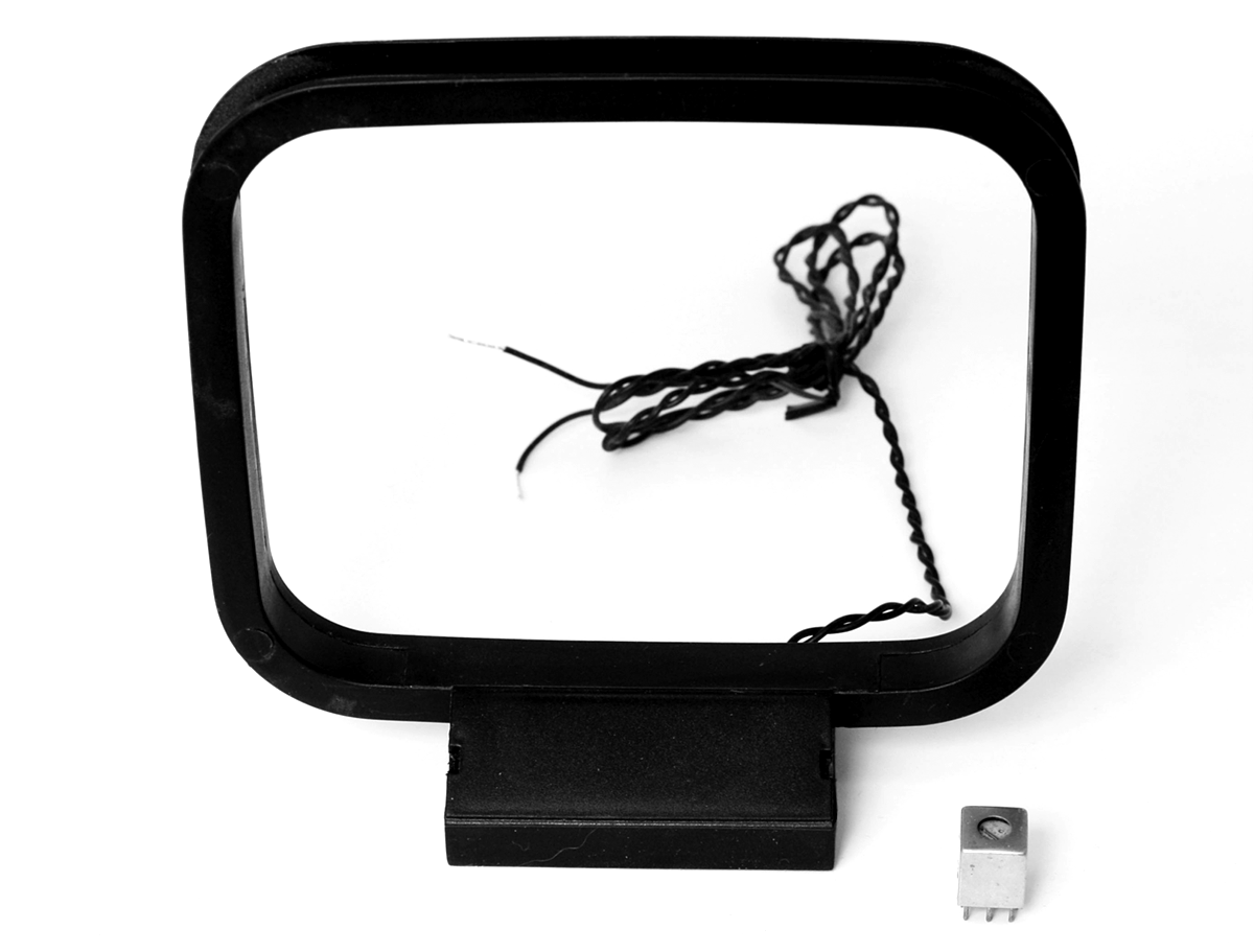
In most high-fidelity home stereo receivers today, the AM radio antenna is just an air dielectric loop (Figure 3-2).
FIGURE 3-2 AM band loop antenna.
The loop antenna in this figure has insufficient inductance to work with any of the standard variable capacitors (e.g., 140 pF to 365 pF). Therefore, this antenna is connected to a step-up RF transformer, and the RF transformer is matched with a standard variable capacitor. In this book, oscillator coils and/or hacked intermediate-frequency (IF) transformers (see lower right-hand corner of Figure 3-2) will be used as the RF transformer for these types of loop antennas. It should be noted that these types of loop antennas are commonly available at MCM Electronics as replacement antennas for stereo receivers.
Variable Capacitors
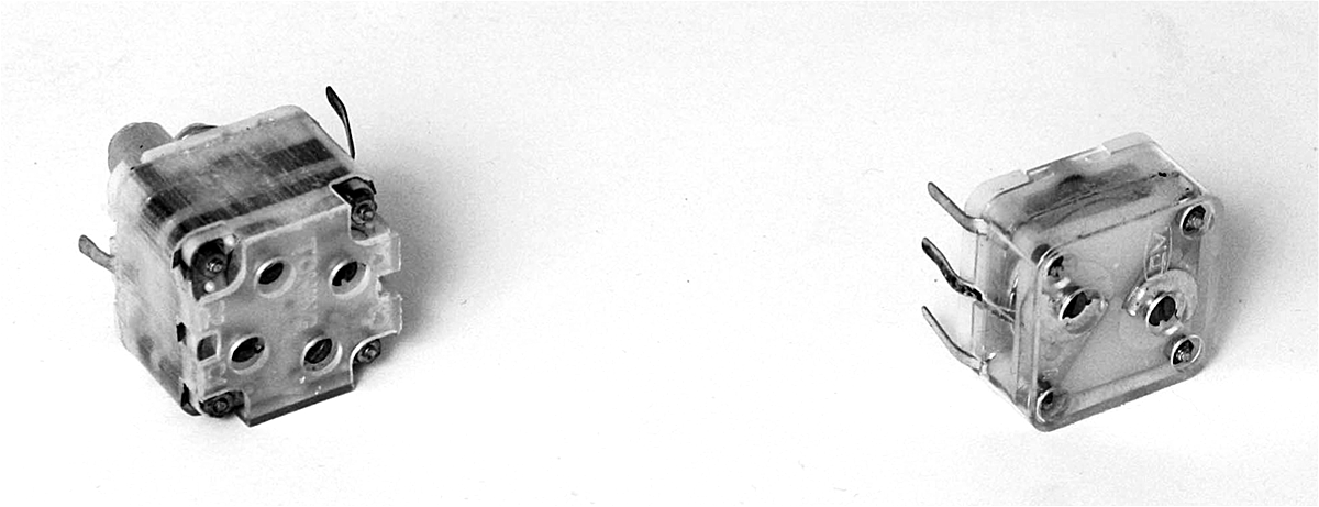
These days, choosing variable capacitors for AM radios is limited to roughly two types of poly-varicon variable capacitors. Poly-varicon variable capacitors use polyester sheets between the plates as opposed to air-dielectric variable capacitors (Figure 3-3). A multiple gang variable capacitor such as a two, three, or four gang variable capacitor refers to the number of sections it has and all sections share a common tuning shaft. In general, a multiple gang variable capacitor is equivalent to a multiple section variable capacitor. However, some multiple section variable capacitors such as dual trimmer variable capacitors have two independent adjustments for varying the capacitance of each section. For this book, the main tuning capacitor is described as an “x” gang variable capacitor or equivalently, an “x” section variable capacitor.
FIGURE 3-3 Variable capacitors using poly material for insulation between plates.
The capacitor on the left in the figure is a twin-section variable capacitor, which commonly has 270 pF in each section. This type of variable capacitor is ideal for a one- or two-section tuned radio-frequency (TRF) radio. It should be noted that a 2.5-mm metric screw is used for adding an extended shaft (via a spacer).
For a superheterodyne radio, the first 270-pF section is matched with an antenna transformer or antenna coil of 330 μH and then with a series capacitor of about 300 pF to 330 pF with the second 270-pF section and a 180-μH coil to form an oscillator/converter circuit.
Four trimmer capacitor shown, but only two are needed. This allows adding roughly up to 20 pF to the main sections of 270 pF. In some cases, the twin variable capacitor comes with 330 pF for each section instead of 270 pF.
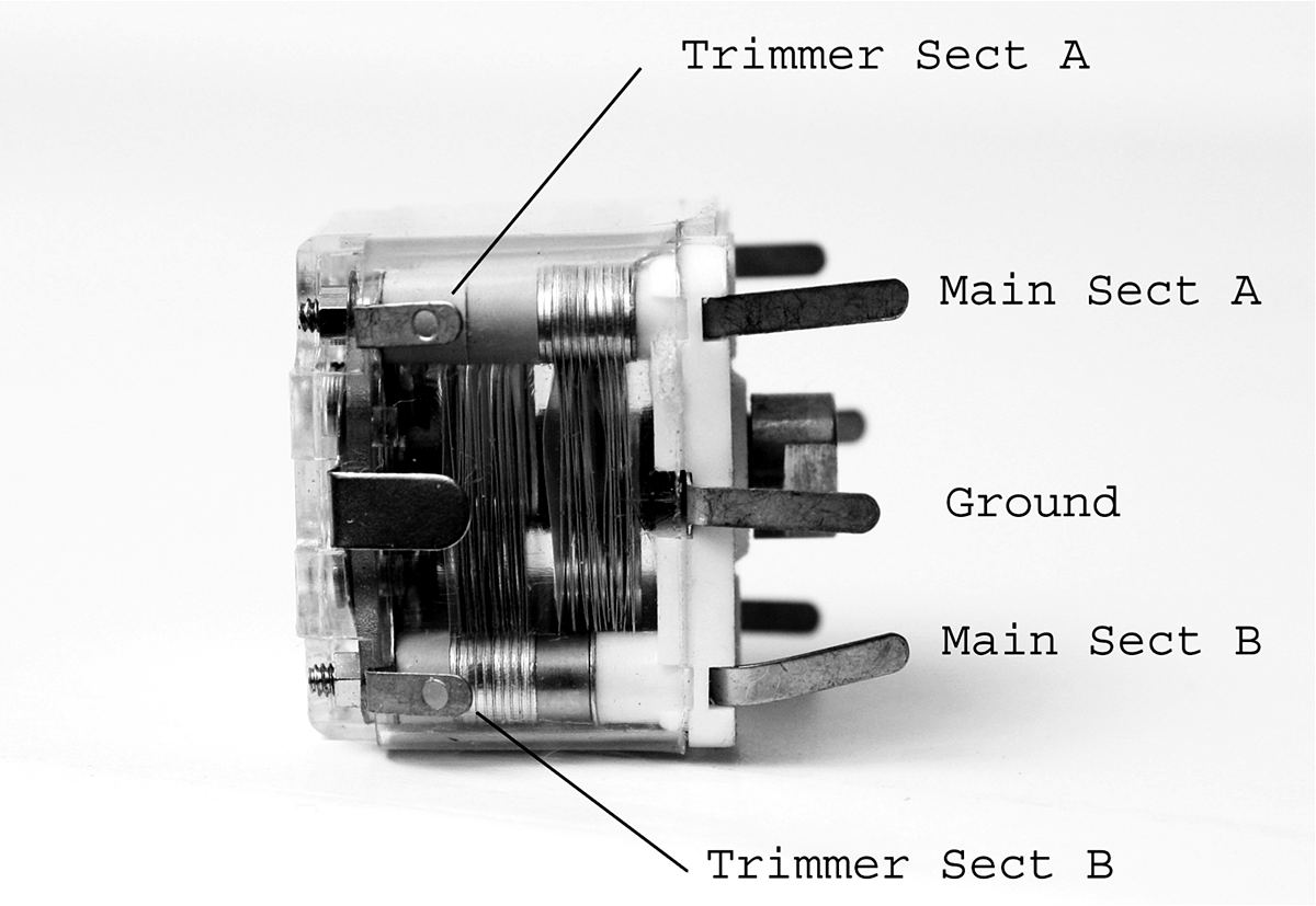
On the right side of Figure 3-3 is another variable capacitor. This capacitor has two unequal sections. One section at 140 pF is dedicated to the antenna coil or antenna transformer, and the other section at 60 pF is used for an oscillator circuit. For identifying the various sections of the twin variable capacitor, see Figure 3-4.
FIGURE 3-4 Twin gang/section variable capacitor.
For the twin gang/section variable capacitor, the trimmer capacitors’ ground connection is internally connected to the ground tab, as seen in the figure. The trimmer-tab connections in general should be tied to each associated main section’s connections (e.g., trimmer section A to main section A and trimmer section B to main section B). A detailed description of the second poly-varicon variable capacitor is provided in Figure 3-5.
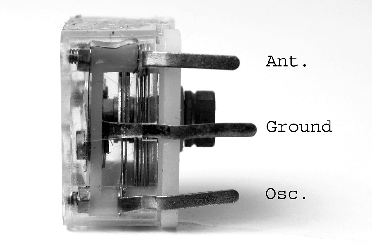
FIGURE 3-5 Two gang variable capacitors for typical transistor radios.
The two trimmer capacitors for the variable capacitor in this figure are always internally tied to each of the antenna section and the oscillator section. Be careful to note the labeling of each tab or lead for “Ant.” and “Osc.” because they are not the same capacitance. If you look carefully, you can see that the oscillator section tab of a two-section variable capacitor leads to fewer plates than the upper tab, which is marked “Ant.”
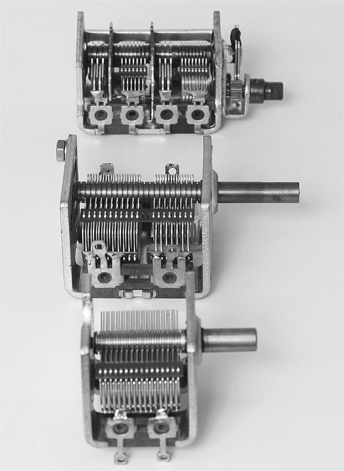
Figure 3-6 shows various air-dielectric variable capacitors, which in general are available on the Web or via eBay.
FIGURE 3-6 Air-dielectric variable capacitors.
The first capacitor shown at the bottom of the figure is a single-section 365-pF variable capacitor. No trimmer capacitor is attached. This type of variable capacitor can be used for TRF, reflex, and regenerative radios but not for superheterodyne radios, which require two or more sections.
In the center of the figure is a two-section (two gang) variable capacitor. This particular capacitor has an antenna section on the left side and an oscillator section on the right side. Notice that the number of plates on the left side (antenna section) is larger than the number of plates on the right side (oscillator section). Not shown, but on the other side of this variable capacitor are adjusting screws for each trimmer capacitor that are connected internally to the antenna and oscillator sections.
Finally the variable capacitor at the top of Figure 3-6 is a four-section capacitor. Two sections are used for the AM band, and the other two are used for the FM band. Since this book is limited to AM radios, only two will be used. Counting from left to right, section 2 is for the oscillator, and section 4 is used for the antenna of a superheterodyne receiver. Also not shown are the trimmer capacitor screw adjustments on the other side of this variable capacitor.
Transistors
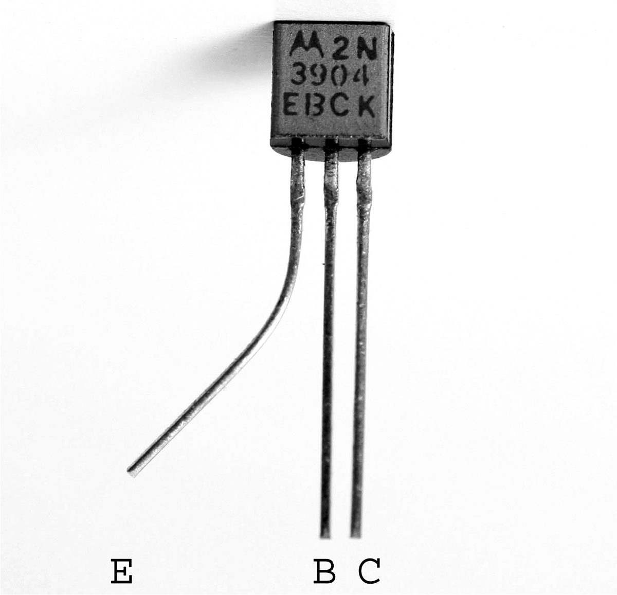
In terms of transistors, the most common lead (terminal) configuration is E, B, C (emitter, base, collector), as shown in Figure 3-7.
FIGURE 3-7 Common silicon transistor.
The figure shows the most common lead configuration for the most common transistors, such as 2N4124, 2N4126, 2N3904 (as shown in the figure), 2N3906, 2N5087, and 2N5089. If other transistors are substituted, the lead configuration diagram can be downloaded from the Web (e.g., go to Google, and type in “2Nxxxx, BCxxx, etc. data sheet”). As shown in Figure 3-7, the base and collector leads are next to each other, causing increased internal capacitance between the base and collector leads.
For high-frequency transistors, which will be used in some designs in this book, the lead terminal configuration is changed to B, E, C (base, emitter, collector), as shown in Figure 3-8.
FIGURE 3-8 High-frequency silicon transistor.
For high-frequency performance, the interelectrode capacitance between the base and collector must be minimized. Hence, in this configuration, the base and collector leads are placed as far apart from each other as possible. An example is the MPSH10, which is used in some circuits in this book. Note that the order of its leads is B, E, and C, which is different from the more common arrangement of E, B, and C.
Earphones
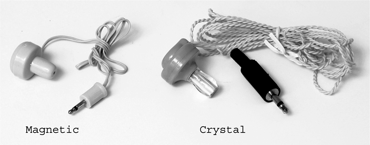
After the AM signal is demodulated and amplified, the listener can use two types of earphones or headphones, either magnetic or crystal (piezoelectric), as shown in Figure 3-9.
FIGURE 3-9 Earphones.
Most magnetic earphones or headphones have impedances from 8 V to 32 V (ohms). However, for lower-power radios, it is recommended to use impedances of 500 V or more. For a very low-powered radio, the crystal earphone or headphone is the best choice. It has an impedance in the thousands of ohms and is suitable for crystal radios as well.
Speakers
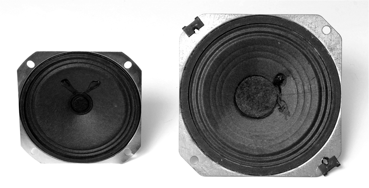
There will be some radios in this book that are not as low powered and can drive loud speakers. A speaker with mounting holes is desired for assembling on a chassis or board via spacers and bolts. Figure 3-10 shows 3-inch and 4-inch speakers.
FIGURE 3-10 Loudspeakers.
Passive Components
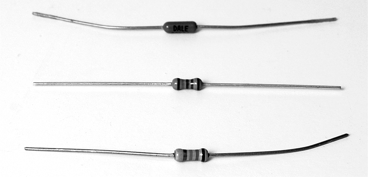
Passive components such as resistors used in the designs are in general 5 percent ¼-W resistors but 1 percent types may be used (Figure 3-11).
FIGURE 3-11 Resistors.
As seen in the figure, generally a 5 percent ¼-W resistor on the bottom will do just fine for most of the designs in this book. More precise 1 percent resistors such as the types shown at the top and center of the figure can be used for circuits requiring more precision, such as phase-shifting circuits or timing or oscillator circuits.
Fixed inductors also will be used in some of the designs, and some of them actually look like resistors (Figure 3-12). The color code is the same as for resistors, in microhenrys (μH). For example, yellow, violet, and red equal 4,700 μH or 4.7 mH. To make sure of an inductor’s value, though, measure with an inductance meter. Generally, the resistance in ohms of the inductor will not match the inductance in millihenrys (mH) or microhenrys (μH). Therefore, if an inductor that looks like a resistor is measured with an ohm meter, the resistance measurement will not match the color code and the user can then deduce that the component is most likely an inductor instead of a resistor.
FIGURE 3-12 Inductors.
Other types of inductors may come in unfamiliar shapes, such as the examples shown in Figure 3-13.
FIGURE 3-13 Other inductors/coils.
For the inductor in this figure, on the left side the value says “221,” which really means 22 plus 1 zero following the 22, for 220 μH. The inductor on the right has three sets of numbers, but the only one that seems to make sense is “330.” But does this mean that the inductance value is 33 plus 0 zero after 33, for 33 μH, or does it mean that the value is literally 330 μH? The measured value is 330 μH.
Therefore, in the case of inductors and capacitors, it is always advisable to measure the component first to make sure (e.g., with an inductance meter for coils and a capacitance meter for capacitors).
For small-value capacitors (5 pF to 4,700 pF), generally, ceramic disk or silver mica types are used. For stability and accuracy, though, silver mica capacitors are preferred (Figure 3-14).
FIGURE 3-14 Small-value capacitors.
Film (e.g., polyester or Mylar) capacitors are also used (Figure 3-15).
FIGURE 3-15 Film-dielectric capacitors.
The markings on many film capacitors are done in two ways. One is in microfarads. Thus the capacitor at the top of the figure is marked “.010,” meaning 0.01 μF. The capacitors at the bottom of the figure are usually marked with a three-digit code in picofarads (pF), with the third digit denoting the number of zeros following the first two digits. For example, “102” means 10 plus two zeros after 10 = 1,000 pF or 0.001 μF.
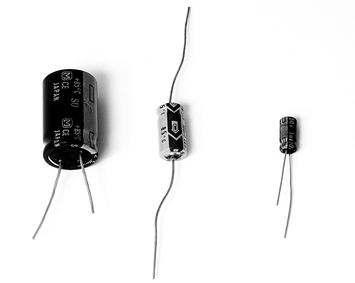
Ceramic, mica, and film capacitors can be connected with the leads either way. But common electrolytic capacitors are polarized and thus are not the type of capacitors that can have leads switched without a problem. The schematic diagram will point out how the electrolytic capacitors should be connected. See the electrolytic capacitors in Figure 3-16, where the markings indicate negative or (–).
FIGURE 3-16 Polarized electrolytic capacitors.
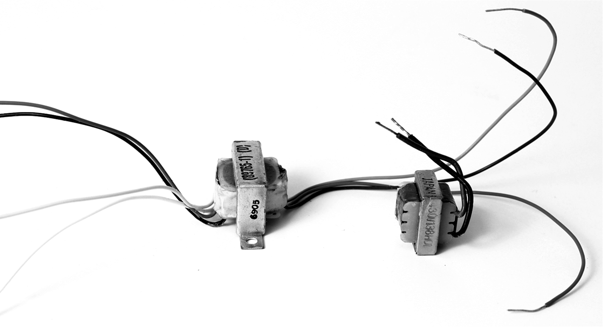
Audio transformers will be used in reflex, regenerative, and superheterodyne radios (Figure 3-17). These audio transformers will be used for extracting audio signals from an amplifier and providing signals suitable to drive earphones or speakers. They will have primary and secondary windings (e.g., at least four leads). Audio transformers normally are available in two types, input or driver transformers and output transformers. In newer audio amplifier designs, audio transformers are not used and are replaced by integrated circuits or discrete transistors.
FIGURE 3-17 Audio transformers.
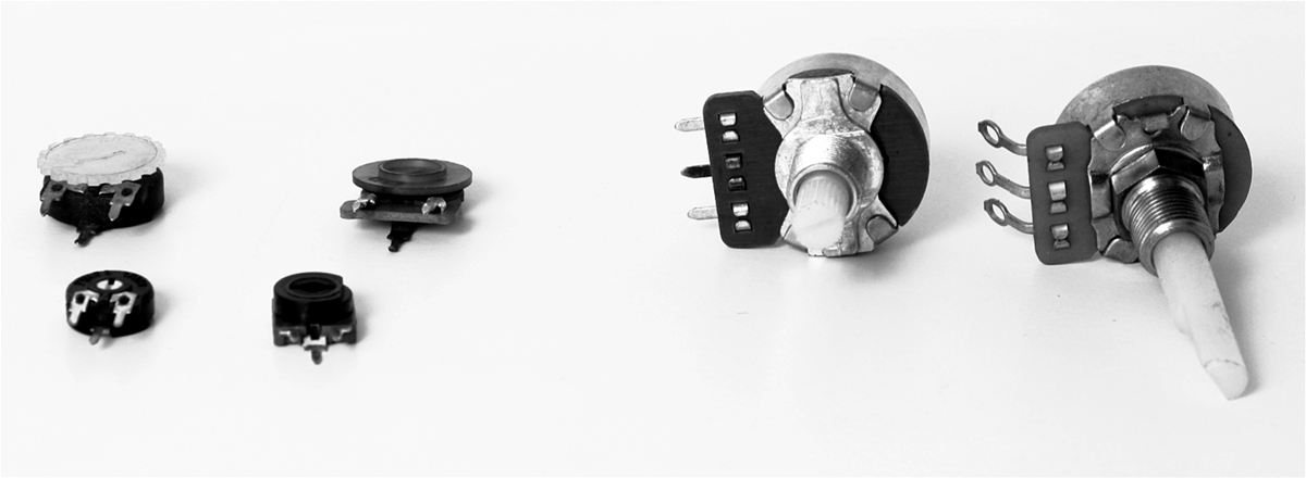
Single-turn variable resistors or potentiometers are shown in Figure 3-18. These generally are used for volume control, especially the ones shown on the right.
FIGURE 3-18 Variable resistors or potentiometers.
Multiple-turn variable resistors or potentiometers will be used for adjusting frequency in an oscillator or levels of a signal. They offer a more precise adjustment than single-turn types (Figure 3-19). The markings can be of two types. One is the exact value in ohms, such as 10K = 10,000 ![]() or 10 k
or 10 k![]() . And the other can be a three-digit code where the last digit means the number of zeros added after the first two numbers, for example, 204 = 20 plus 4 zeros = 200000 = 200,000
. And the other can be a three-digit code where the last digit means the number of zeros added after the first two numbers, for example, 204 = 20 plus 4 zeros = 200000 = 200,000 ![]() = 200 k
= 200 k![]() .
.
FIGURE 3-19 Multiturn variable resistors.
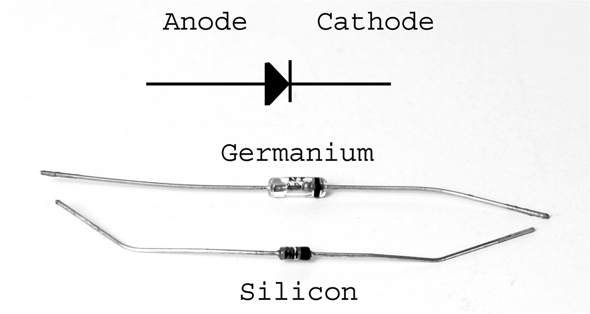
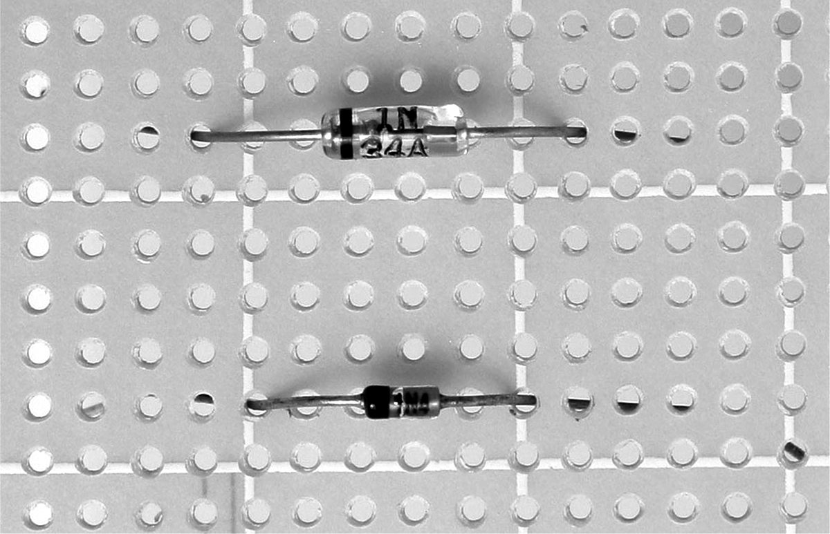
Finally, here are a few words about diodes (Figure 3-20). The marking on small signal diodes usually is a band or stripe that denotes the cathode. These diodes are inserted into a perforated (perf) board by bending the leads to at least ¼ inch of lead length from each side of the body of the diode to avoid stress that otherwise would crack the glass casing. See the example in Figure 3-21.
FIGURE 3-20 Diodes.
FIGURE 3-21 Diodes mounted on a board with adequate lead length prior to bending the leads.
Vector and Perforated Boards
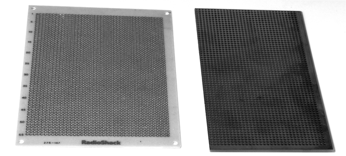
Vector and perforated boards can be used for building radios (Figure 3-22). On the left is a perforated (perf) board. Although the radios can be built using a perf board, a vector board with a ground plane is preferred. And on the right is a vector board with the ground-plane side up. Generally, the components are placed on the ground-plane side, and wiring is done on the opposite side (the side without a ground plane).
FIGURE 3-22 Perforated (perf) and vector boards.
It should be noted that vector and perf boards generally have 100-mil spacing, which is suitable for mounting dual in-line integrated circuits, headers (berg connector heads), and 7-mm coil. A 10-mm coil can be mounted as well by rotating the coil by 45 degrees.
Copper-clad boards, while not as “permanent” in building radios, are a good choice for building the first prototype radios (Figure 3-23). Debugging on copper-clad boards is much easier than on vector or perf boards.
FIGURE 3-23 Copper-clad board.
Hardware
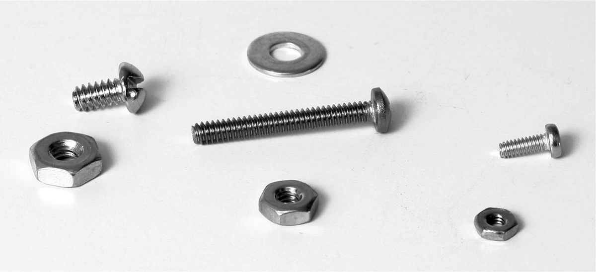
The hardware needed for the projects in this book includes 6-32, 4-40, and 2-56 nuts and bolts, along with washers (Figure 3-24). Not shown are 2.5-mm metric screws, which are used with poly-varicons (poly-variable capacitors).
FIGURE 3-24 Nuts and bolts.
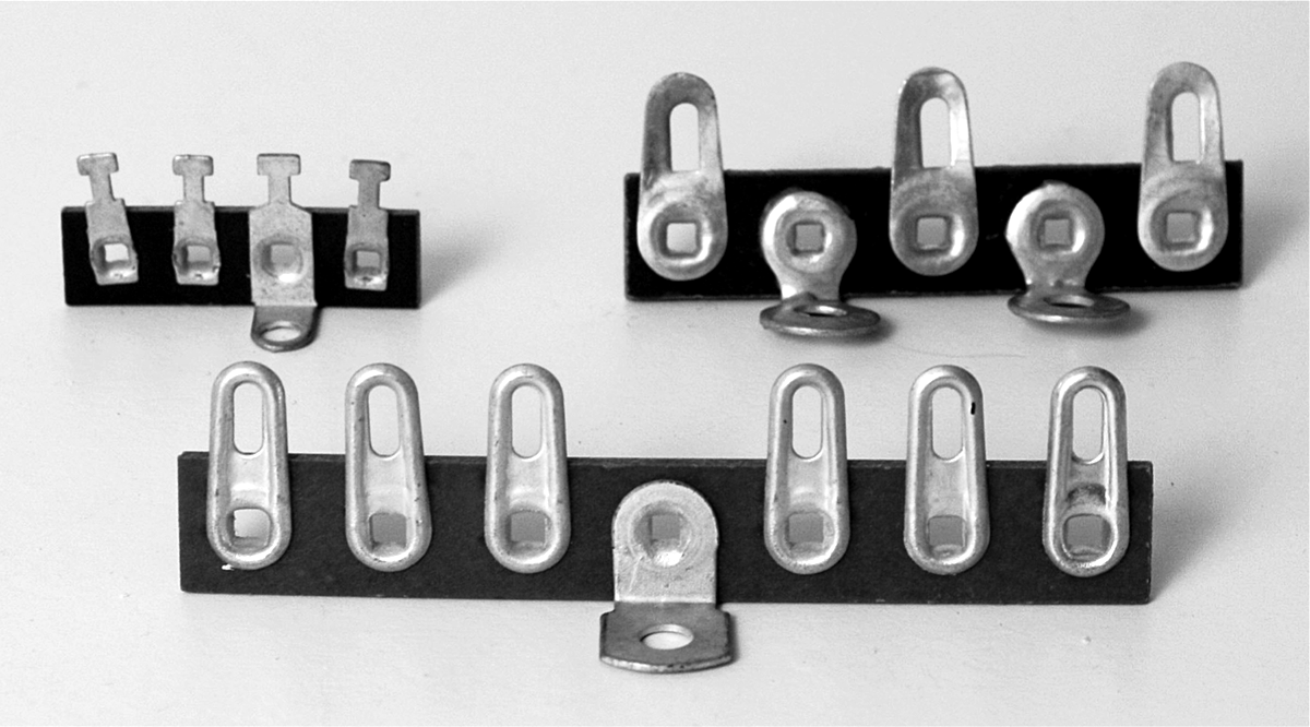
The tie points shown in Figure 3-25 are useful for connecting wires.
FIGURE 3-25 Tie points.
To mount the speaker, antenna coil, or vector or perf board, spacers are needed. The ones shown in Figure 3-26 use 4-40 threads, but other spacer sizes may be used.
FIGURE 3-26 Spacers.
Generally, an oscillator coil, which has a tapped primary winding and a secondary winding, is used for the local oscillator circuit for superheterodyne receivers. However, some have an inductance value suitable for an RF amplifier circuit. See the oscillator coil in Figure 3-27, which is generally used with a 60-pF variable capacitor for an oscillator circuit but is also suitable for use with a loop antenna.
FIGURE 3-27 Oscillator coil, IF transformer, or adjustable coil/inductor.
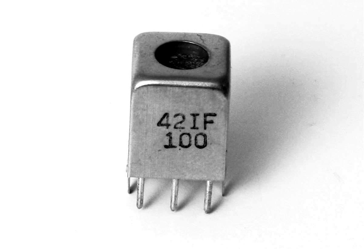
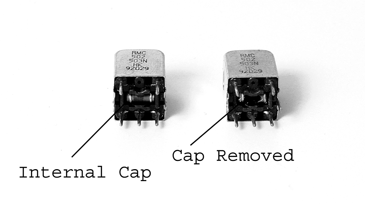
It was found that some intermediate-frequency (IF) transformers can be converted into oscillator coils by chipping off their internal capacitors. Hacking IF transformers into oscillator or RF coils can be very useful because the inductances of IF transformers and their turns ratios make them ideal in some cases (e.g., for a low-power superheterodyne radio) (Figure 3-28).
FIGURE 3-28 IF transformer with internal capacitor and IF transformer with internal capacitor removed.
Parts Suppliers
See Appendix 1.
