Chapter 10
Exotic or “Off the Wall” Superheterodyne Radios
In Chapters 8 and 9, the superheterodyne radios were designed in a straightforward manner. The radio-frequency (RF), intermediate-frequency (IF), and audio signals were amplified with dedicated amplifiers. This chapter presents reflex superheterodyne radios. In one design, the mixer oscillator converter circuit doubles as an audio power amplifier. And in another design, the oscillator converter stage and IF amplifier circuit also operate as audio driver and audio output amplifiers.
A One-Transistor Superheterodyne Radio
Chapter 6 introduced a single-transistor reflex radio. This one-transistor radio was a tunable radio-frequency (TRF) circuit with the detected output recirculated back to the RF amplifier to increase the audio level. The selectivity of this reflex radio was adequate, and the audio output was suitable for driving generally high-impedance earphones of 2,000 Cl or more. The selectivity of the reflex radio is limited by the loading of the antenna coil via the input to its transistor circuit.
Selectivity can be increased by adding a second stage of RF tuning at the collector of the one-transistor circuit. However, more often than not, undesirable oscillations will occur with a tuned circuit (e.g., antenna coil and variable capacitor) at the input and another tuned circuit at the output. The reason is that the antenna coil is receiving the RF signal everywhere, including the amplified RF signal from the collector. So is there another way to increase selectivity? Yes, one can try designing a superheterodyne radio with one transistor.
However, because we are using just one transistor, there is a limitation as to how much gain is available for amplifying RF and audio-frequency (AF) signals. One objective of this radio is to drive a low-impedance earphone (e.g., 32 ![]() ). Thus, in order to provide sufficient audio drive to a low-impedance earphone, this radio will drain current on the order of many milliamps (i.e., not a very low-power receiver).
). Thus, in order to provide sufficient audio drive to a low-impedance earphone, this radio will drain current on the order of many milliamps (i.e., not a very low-power receiver).
Design Considerations for a One-Transistor Superheterodyne Radio
The converter oscillator circuit, which usually runs at a couple or few hundred microamperes now will operate at about 10 times the current, anywhere from a few to about 10 milliamperes. The higher operating current is required because the converter oscillator circuit will pull the additional duty of amplifying audio signals. However, the higher collector current increases the gain of the converter oscillator circuit, which can lead to parasitic oscillations. In addition, the higher collector current leads to higher oscillation signals at the collector of the converter transistor, which robs the audio-signal’s voltage swing. Therefore, it is desirable to limit the oscillator’s output voltage.
Another design consideration for a one-transistor superheterodyne receiver is demodulation after the IF filter. Because the converter oscillator transistor is running at such a high collector current, there is a tremendously large oscillator signal at input of the IF filter that does not get filtered out. This large oscillator signal added on top of the IF signal then hampers envelope detection of the 455-kHz IF signal. In reality, for single-tuned IF transformers, the signal from the output of the first IF transformer contains both signals from the IF of 455 kHz and also the oscillator frequency, which ranges from 1 MHz to 2 MHz. Usually, the first IF amplifier does not have a problem handling both signals, and the output from the first IF amplifier is fed to a second IF transformer, which then filters out almost completely the oscillator signal while passing the 455-kHz IF signal.
Thus at least two stages of IF filtering may be required to reject the oscillator’s signal from the converter oscillator circuit while allowing the 455-kHz IF signal to be envelope detected.
Finally, the operating voltage of a one-transistor superheterodyne radio is normally in the range of 9 volts to 18 volts. At the transistor’s collector terminal, three signals are superimposed. They are the oscillator signal, the 455-kHz IF signal, and the audio signal. Thus, for the following design, a 9-volt supply will be used. Figure 10-1 shows a block diagram for a one-transistor superheterodyne radio.
FIGURE 10-1 Block diagram of a one-transistor reflex superheterodyne radio.
The radio station’s RF signal is received by antenna coil L1, which couples the RF signal via a secondary winding of L1 to converter circuit Q1. The output of Q1 feeds an IF transformer and an audio transformer. The output of the first IF T2 transformer then is coupled with a second IF transformer T3, which provides sufficient rejection of the oscillator’s signal for envelope detection of the 455-kHz IF signal. Detector D3 then provides an audio signal that is fed back to the converter oscillator transistor’s input for audio amplification. Audio transformer T5 is connected to the output of the converter oscillator transistor Q1 for extraction of the amplified audio signal. This amplified audio signal then has sufficient current to drive a low-impedance earphone.
Parts List
• Cl: 100 μF, 16 volts
• C2, C3, C4, C9: 0.01 μF
• C6: 0.0039 μF
• C7, C8: 1 μF, 35 volts
• Rl: 180 ![]()
• R2: 390 k![]()
• R3: 47 k![]()
• R4: 20 k![]()
• VR1: 50 k![]()
• Tl oscillator coil: 42IF110
• T2, T3 IF transformer: 42IF103
• T4 audio-drive transformer: 10 k ![]() primary, 10 k
primary, 10 k ![]() secondary
secondary
• T5 audio output transformer: 1 k ![]() primary, 8
primary, 8 ![]() secondary
secondary
• LI antenna coil: 600 μH to 680 μH primary, 10 turns for secondary winding
• L2: 150 μH
• Dl, D2: 1N914
• D3, D4, D5: 1N270 or 1N34
• Ql: 2N5089
• VC1: two-gang variable capacitor 140 pF and 60 pF
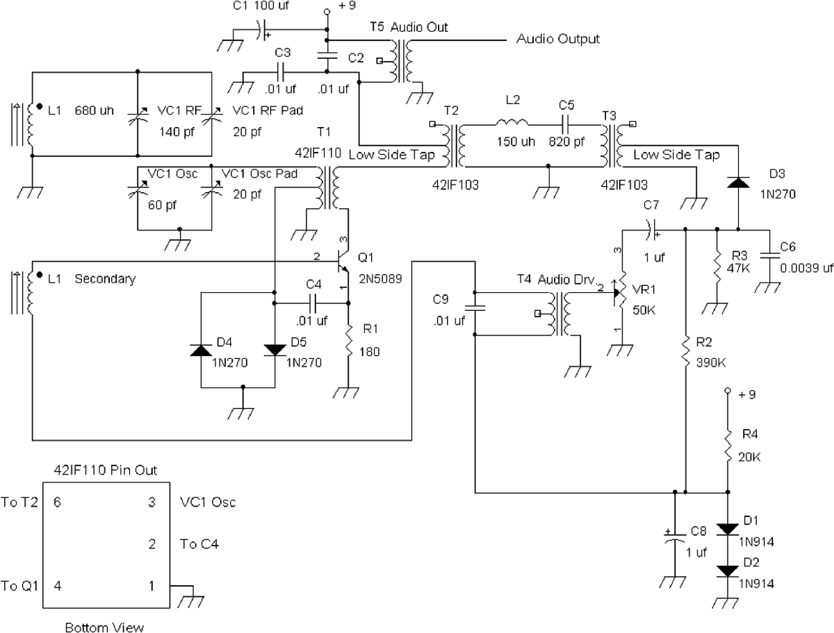
Figure 10-2 presents the schematic for the one-transistor radio. As shown in the schematic, the RF signal from the tuned circuit consisting of VC1 RF and L1 is connected to the base of Q1. The collector of Q1 is connected to a secondary winding of the oscillator coil T1 that feeds energy back to its primary winding to provide a reliable oscillation signal from 1 MHz to 2 MHz at the emitter of Q1. At the low side of the primary winding of T1, two diodes are wired back to back to provide amplitude limiting of the oscillator signal because the operating collector current of Q1 is biased to a much higher than “normal” direct-current (DC) current. With a local oscillator signal at the emitter of Q1 and an RF signal at the base of Q1, a multiplying effect of the two signals occurs to provide an IF signal at 455 kHz at the collector of Q1. The first IF transformer T2 provides extraction of the IF signal but still contains some of the local oscillator’s signal. For further attenuation of the local oscillator signal while passing the IF signal, a series resonant circuit formed by L2 and C5 is connected to a second IF transformer T3 that passes signals around 455 kHz and provides further attenuation of the local oscillator signal, whose frequencies range from 1 MHz to 2 MHz. The signal from the IF transformer T3 provides further attenuation of the local oscillator signal and is connected to D3 for envelope detection of the 455-kHz amplitude-modulated (AM) signal. The detected signal now is an audio signal that is connected to the primary winding of audio transformer T4, whose secondary winding is connected in series with the secondary winding of L1.
FIGURE 10-2 Schematic diagram of the one-transistor reflex radio.
Thus the base of Q1 has both RF signals from L1 and AF signals via T4. Amplified audio signals at the collector of Q1 are extracted via audio transformer T5. Sufficient audio signal current is provided by the secondary winding of T5 to drive a low-impedance earphone. Also, to conserve battery life, a power switch may be connected in series with the battery.
![]()
Although the one-transistor superheterodyne radio provides higher selectivity than the one-transistor reflex radio, the sensitivity is about the same. Thus the one-transistor superheterodyne reflex radio generally performs not that much better than a one-transistor TRF reflex radio such as the one shown in Chapter 6. This radio is more of an exercise in circuit design and is neither low power nor high performance.
If time permits, a second one-transistor reflex superheterodyne radio will be designed. But there is only so much one can do with just one transistor to convert RF signals into an “amplified” IF signal while trying to provide audio amplification as well. See Chapter 23 for an update of the one-transistor reflex superheterodyne radio. In the next design using two transistors, the performance is improved significantly, although this design is not considered to be low power.
A Two-Transistor Superheterodyne Radio
Although neither one- nor two-transistor superheterodyne radios generally were made commercially, there were three-transistor designs. For example, in 1960, the Truetone Model DC3090 was sold. This was a three-transistor superheterodyne design with a converter circuit, an IF/AF amplifier, and an audio power amplifier. The detected AM signal from the IF amplifier was fed back to the IF amplifier for further AF amplification, and the audio signal from the IF amplifier then was connected to the audio power amplifier for driving a loudspeaker. Thus the Truetone radio was a reflex radio using the IF amplifier for amplifying audio signals and 455-kHz IF signals from the converter circuit.
Thus the Truetone radio had the following characteristics:
1. A converter oscillator circuit for translating the RF signal from an antenna coil to an amplified IF signal using a first transistor
2. An IF amplifier with two IF transformers using a second transistor
3. Audio amplification with two stages, a first stage via the IF amplifier and a second stage via an audio output amplifier using a third transistor to drive a speaker
However, the design for a two-transistor radio can have the same characteristics if the converter oscillator circuit works as the first-stage audio amplifier. Thus the two-transistor superheterodyne radio has the following characteristics:
1. A converter oscillator circuit for translating the RF signal from an antenna coil to an amplified IF signal and for amplifying audio signals from the detector circuit using the first transistor
2. An IF amplifier with two IF transformers that also provides large audio signal amplification to drive a speaker using the second transistor
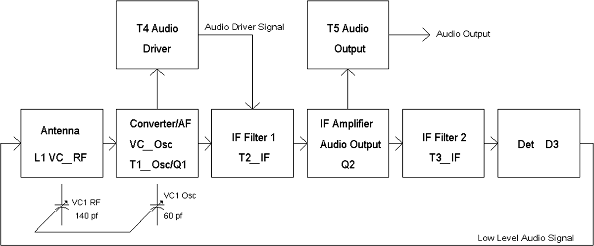
In both cases, the three- and two-transistor designs have a converter stage, an IF stage, and two stages of audio amplification. But the two-transistor superheterodyne radio design has sort of a two-stage reflex circuit, whereas the three-transistor radio has a one-stage reflex circuit. Figure 10-3 presents the block diagram for a two-transistor superheterodyne radio.
FIGURE 10-3 Block diagram of the two-transistor superheterodyne radio.
RF signals are connected to the input of converter oscillator circuit Q1 and T1 to provide a 455-kHz signal to the first IF filter T2. The output of T2 is connected to an IF amplifier (Q2) for further amplification of the 455-kHz IF signal. The output of Q2 is connected to the second IF transformer T3, whose secondary winding provides an AM signal for envelope detection via diode D3. Audio signals via D3 then are fed back to the input of Q1 to further amplify the detected AM signal. The amplified audio signal from Q1 via audio driver transformer T4 then is coupled to the input of Q2 for providing large audio signals that are extracted by audio output transformer T5 to drive a loudspeaker.
Parts List
• Cl, C3, C4, C6: 0.01 μF
• C2: 0.0047 μF
• C5: 100 μF, 16 volts
• C7, C10, C11 : 1 μF, 35 volts
• C8, C9: 0.0033 μF
• Rl, R4: 22 k![]()
• R2: 1,000 ![]()
• R3: 24 ![]()
• R5: 510 k![]()
• VR1: 50-k![]() pot
pot
• T1 oscillator coil: 42IF100
• T2 IF transformer: 42IF101, use low side tap on primary winding
• T3 IF transformer: 42IF103, use low side tap on primary winding
• T4 audio driver transformer: 10 k![]() primary, 10 k
primary, 10 k![]() secondary; use the CT in the secondary for 2.5 k
secondary; use the CT in the secondary for 2.5 k![]() or 10 k
or 10 k![]() primary, 2 k
primary, 2 k![]() secondary
secondary
• T5 audio output transformer: 500 ![]() primary, 8
primary, 8 ![]() secondary
secondary
• Dl, D2: 1N914
• D3: 1N270 or 1N34
• Ql, Q2: 2N3904
• VC1: two gang-variable capacitor 140 pF and 60 pF
• LI antenna coil: 600 μH to 680 μH primary, 10 to 20 turns for secondary winding
• L2: 4.7-mH inductor
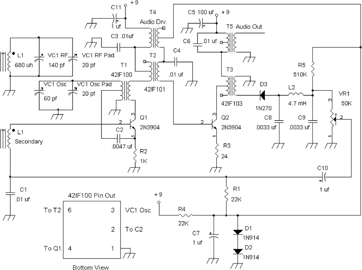
Figure 10-4 presents the schematic diagram of the two-transistor two-stage reflex superheterodyne radio. As seen in this diagram, a 9-volt battery will be used as the power supply, and the radio will drain around 10 mA to 20 mA for driving a loudspeaker.
FIGURE 10-4 Schematic diagram of the two-transistor superheterodyne radio.
RF signals are received via antenna coil L1, which is tuned with variable capacitor VC1 RF. These RF signals are connected to the base of converter oscillator transistor Q1, which has a DC collector current at the typical hundreds of microamperes. The oscillator circuit consists of the collector output of Q1 coupling back to the input (emitter) of Q1 via the secondary winding of T1 and its tapped primary winding, respectively.
Because the emitter of Q1 has a large oscillator signal, Q1 is driven into sufficient distortion that the small RF signal coupled with the base of Q1 is effectively multiplied with the oscillator signal. Stated in another way, the large-amplitude oscillator signal results in a time-varying transconductance, where the time-varying function is the oscillator’s signal.
From the collector output terminal of Q1 then is a 455-kHz IF signal that is connected to the primary winding of the first IF transformer T2. The signal from the secondary winding of the IF transformer then is connected to the base of Q2 for amplification of the 455-kHz signal.
Because Q2’s collector is operating at a direct current of about 15 mA, generally one would think that the input resistance at the base of Q2 would be in the hundreds of ohms (e.g., 250 V or less), which can excessively load down the signal from T2’s secondary winding. However, because the emitter of Q2 has a 24-V resistor to ground, the actual input resistance is about the transistor’s current gain (beta or Hfe, typically 100) times 24 V, which is about 2,400 V. Thus the emitter 24-V resistor raises the input resistance while essentially providing about the same voltage gain as if Q2 were biased at (typically) 1 mA of collector current with the emitter bypassed to ground with a capacitor.
The amplified IF signal then is connected to the second IF transformer T3, and the secondary winding of T3 is connected to D3 for demodulation of the 455-kHz AM signal. Because the demodulated AM signal is going to be recirculated into the converter oscillator transistor Q1, it is essential to remove any 455-kHz signal prior to connection to the base of Q1 via the secondary winding of L1, the antenna coil. Therefore, a low-pass filter formed by C8, L2, and C9 removes substantially the 455-kHz IF signal component from the detector diode D3 while coupling an audio signal to the base of Q1 via the secondary winding of L1.
At audio frequencies, the converter oscillator circuit has an input resistance of about 100,000 ![]() (beta times R2 = 1,000
(beta times R2 = 1,000 ![]() , where beta = 100). The primary impedance of T4 is in fact about 10 kV because the tapped secondary of T4 is being loaded by the input resistance of Q2, which is 2,400 V. Recall that the tapped secondary winding of T4 should be 2,500 V. Thus there is close to an optimal power transfer in impedance matching for T4 into Q2, and the audio-voltage gain from the base of Q1 to the base of Q2 is about 5. The audio gain from the base of Q1 to its collector is 10 k
, where beta = 100). The primary impedance of T4 is in fact about 10 kV because the tapped secondary of T4 is being loaded by the input resistance of Q2, which is 2,400 V. Recall that the tapped secondary winding of T4 should be 2,500 V. Thus there is close to an optimal power transfer in impedance matching for T4 into Q2, and the audio-voltage gain from the base of Q1 to the base of Q2 is about 5. The audio gain from the base of Q1 to its collector is 10 k![]() /1 k
/1 k![]() = 10. But because the center tap of the secondary of T4 is used, we only get half the audio-signal voltage, which is connected to the base of Q2.
= 10. But because the center tap of the secondary of T4 is used, we only get half the audio-signal voltage, which is connected to the base of Q2.
With the amplified (T4) audio signal coupled to the base of Q2, the collector of Q2 supplies sufficient current to output transformer T5 for driving a loudspeaker at its secondary winding. The DC collector current of Q2 is set at about 15 mA with a 500-V impedance load to allow for 7.5 volts peak or 15 volts peak to peak of alternating-current (AC) signal swing. Note that the term impedance is used instead of resistance. Transformer T5 allows the audio-signal voltage at the collector of Q2 to swing above the 9-volt power supply. Thus the 15 mA of collector current allows the collector to swing about 7.5 volts above the 9 volts. For power conservation, the reader may connect a power switch in series with the battery.


