Chapter 4
Building Simple Test Oscillators and Modulators
Before any of the radios are presented, it would be preferable to build some simple test equipment. This chapter introduces the amplitude modulated (AM) signal and various ways to generate radio-frequency (RF) and intermediate-frequency (IF) signals for testing radio projects.
The Continuous-Wave Signal
A continuous-wave signal is defined by a fixed amplitude and a fixed frequency. In an audio continuous-wave signal, this is better known as a tone.
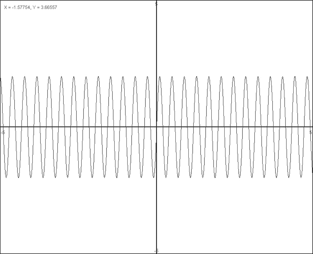
The simplest continuous waveform is a sine-wave signal such as seen in Figure 4-1. The sine-wave signal may represent an RF signal.
FIGURE 4-1 A continuous-wave (sine-wave) signal.
However, a continuous wave (CW) signal, on its own, does not send much information, such as music or voice. A CW signal can be turned on and off for sending coded messages or for controlling a device. For example, Morse code is sent for providing alphanumeric information. Or the condition of a CW signal that is on can be used to keep a relay switch in the “on” state.
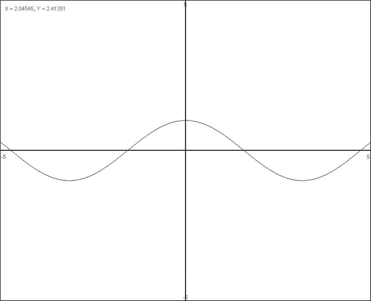
To convey voice or music, however, the CW signal must be modulated in some form. That is, the amplitude, phase, and/or frequency of the CW signal must be related to another signal. In this book, amplitude modulation (AM) is discussed because the receivers we will be building are AM radios. Figure 4-2 shows a lower-frequency signal that is a modulating signal representing an audio signal.
FIGURE 4-2 A lower-frequency signal such as a modulating signal.
The Amplitude-Modulated Signal
An amplitude-modulated (AM) signal is generated by changing the amplitude of the RF CW signal (e.g., see Figure 4-1) with a modulating signal (e.g., see Figure 4-2). At first glance, Figure 4-3 looks as if the CW RF signal from Figure 4-1 has been multiplied by the audio signal, as seen in Figure 4-2. Well, not quite, but almost.
FIGURE 4-3 An amplitude-modulated (AM) signal.
If the audio signal is faded to silence, we would get zero (flat line) in Figure 4-2, which when multiplied by the RF carrier waveform of Figure 4-1 would result in a flat line or zero as well (zero times anything is zero). But we know that when the audio signal is faded to zero, we should just get the unmodulated waveform or CW signal, as seen in Figure 4-1.
So the answer really is that the RF CW waveform of Figure 4-1 is multiplied by (1 + the audio waveform of Figure 4-2) = the amplitude-modulated (AM) waveform of Figure 4-3.
The 1 added to the audio waveform is essential in preserving the shape of the modulating audio waveform on the envelope of the modulated RF CW signal in Figure 4-3. In this way, if the audio waveform fades to zero, we just get Figure 4-1, a CW RF signal, which is what we would expect.
First Project: A CW RF Test Oscillator
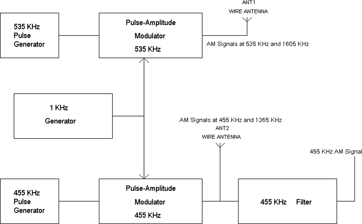
Before the specific schematic is shown, let’s take a look at the big picture. A test generator consisting of a CW oscillator will be used for testing the tuning range, 535 kHz to 1,605 kHz, of the radios. A modulator will be added with an audio-frequency oscillator to produce amplitude modulation of the CW signal. Similarly, a second test oscillator is shown for tuning the 455-kHz IF amplifiers of superheterodyne radios. Figure 4-4 presents a block diagram of the test oscillator system.
FIGURE 4-4 A block diagram of a test generator.
In this block diagram, there are two CW oscillators at 535 and 455 kHz. Both CW oscillators produce pulses, not sine waves. Pulses also generate harmonic frequencies of 535 kHz and 455 kHz. Thus, using pulse generators avoids the need to build extra oscillators at other frequencies. For example, the third harmonic of 535 kHz is 1,605 kHz, and the third harmonic of 455 kHz is 1,365 kHz.
Each pulse generator is fed to a pulse modulator, which changes the amplitude of the 535-kHz and 455-kHz pulses via a 1-kHz audio generator. The output of the modulators then provides amplitude-modulated (AM) signals at 535 kHz and 455 kHz and their respective harmonics.
A simple wire may be placed near the radio to confirm the tuning range of the radio at the low end, 535 kHz, and at the high end, 1,605 kHz. The output of the 455-kHz modulator is connected to a 455-kHz band-pass filter to provide only an amplitude-modulated (AM) signal at 455 kHz for IF amplifier alignment in superheterodyne radios.
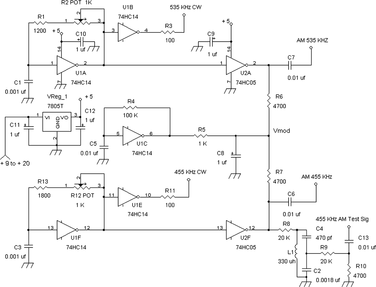
The entire test oscillator is shown in Figure 4-5. However, each functional section will be covered separately.
FIGURE 4-5 Schematic of the test generator.
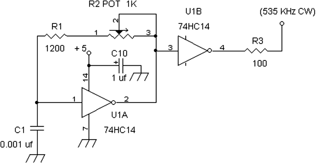
Now let’s take a look at a pulse generator (CW) (Figure 4-6).
FIGURE 4-6 Pulse-generator circuit for a CW signal.
Integrated circuit U1A (74HC14) is a special logic inverter with an input circuit that has a hysteresis characteristic via a Schmitt trigger, which makes it ideal for making a relaxation oscillator for generating CW waveforms. Basically, the tripping-point voltage at the input changes depending on what the output state is.
When the output is high at pin 2, the input at pin 1 rises slowly owing to the low-pass filtering effect of R2, R1, and C1. Note: R2 preferably is a multiturn trim pot. Eventually, the voltage at pin 1 rises sufficiently to cause the inverter to output a low signal. Once the output is low, though, the input trigger point at the input is also lower. Thus capacitor C1 has to discharge to that lower trigger point, Vlow_trigger. When it does, the inverter goes high but also causes the input to trigger at a higher voltage, Vhigh_trigger. As a result of the dynamic nature of how the input trigger voltage changes, an oscillating signal occurs between the voltages of Vhigh_trigger and Vlow_trigger.
Both Vhigh_trigger and Vlow_trigger will vary as a function of the supply voltage. Thus a supply voltage that is not regulated will cause a shift in oscillating frequency. Therefore, it is advised to use a regulated 5-V supply when stability of the preset frequencies is desired.
The 74HC14 inverter gate can provide oscillating waveforms to at least 10 MHz and at nearly but not perfectly symmetric square waves. The frequency of oscillation is about 1/[(R1 + R2)C1] in Figure 4-5. R2 is adjusted to 535 kHz via measuring with a frequency counter (e.g., a digital voltmeter with frequency counter).
If a frequency counter is not available, use a radio with digital readout tuned to 1,070 kHz (second harmonic of 535 kHz), connect a wire to the R3 terminal, and place the wire near the radio. Listen for the radio’s hiss level to go down when tuned to 1,070 kHz while adjusting R2.
For higher oscillation frequencies, one can use a 74AHC14 gate instead, but the 74HC14 type is more common. However, when using a 74AHC14 gate, values of C1, R1, and R2 may change.
Other inverters can be used, such as the 74C14, which is slower in speed than the 74HC14 but should work. Also, the 74HCT14 will work, but the frequency-of-oscillation formula is not the same as for the 74HC14, so some experimentation by the reader is required.
For really high-frequency oscillations, a 74AC14 or 74ACT14 will work up to frequencies well beyond 30 MHz (probably up to about 70 MHz or 100 MHz), but the reader will have to experiment to determine the resistor and capacitor combinations.
As a starting point, if one wants to experiment with inverter gates other than the 74HC14, try using C1 = 0.001 μF, and replace R1 with a 470-![]() resistor and R2 with a 5-k
resistor and R2 with a 5-k![]() multiturn pot. Also, the waveform symmetry of a 74HCT14 (or 74ACT14) inverter oscillator circuit is not as close to a 50 percent duty cycle as the 74HC14 (or 74AC14) part.
multiturn pot. Also, the waveform symmetry of a 74HCT14 (or 74ACT14) inverter oscillator circuit is not as close to a 50 percent duty cycle as the 74HC14 (or 74AC14) part.
Modulator Circuit for the CW Generator
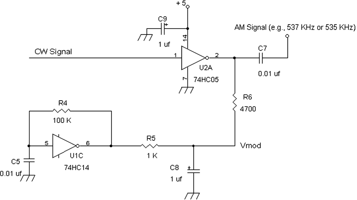
The type of amplitude modulator that is used is known as a transistor drain modulation (Figure 4-7). U2A (74HC05) is an inverter gate with an open-drain output. This means that the output is a short circuit to ground when the input (pin 1) is logic high and an open circuit when the input to U2A is logic low.
FIGURE 4-7 Pulse-amplitude-modulating circuit.
U1E (74HC14), another hysteresis oscillator circuit, supplies a 1-kHz signal to R5 and C8. The voltage across capacitor C8 is a triangle wave with a direct-current (DC) offset voltage to form a modulation voltage, Vmod. A CW signal (in this case from a 535-kHz hysteresis oscillator) is connected to the input of open-drain inverter gate 74HC05. By varying the voltage on pull-up load resistor R6, the output of U2A generates pulse amplitude modulation on the CW signal.
Now let’s take a closer look at a pulse-amplitude-modulation circuit and its signals.
In Figure 4-8, a pulse amplitude modulator switches a CW signal on and off via a load or pull-up resistor. The CW signal causes the output to switch in two signal voltages, zero when the switch is grounded and V when the switch is in the open position.
FIGURE 4-8 Modulating circuit—voltage V is varied to provide pulse amplitude modulation.
When V, the pull resistor’s voltage source, is at a fixed voltage, the output would see something like Figure 4-9.
FIGURE 4-9 CW pulse signal for a fixed voltage V.
When V is increased, we would see something at the output like Figure 4-10.
FIGURE 4-10 CW pulse signal is increased when V is increased.
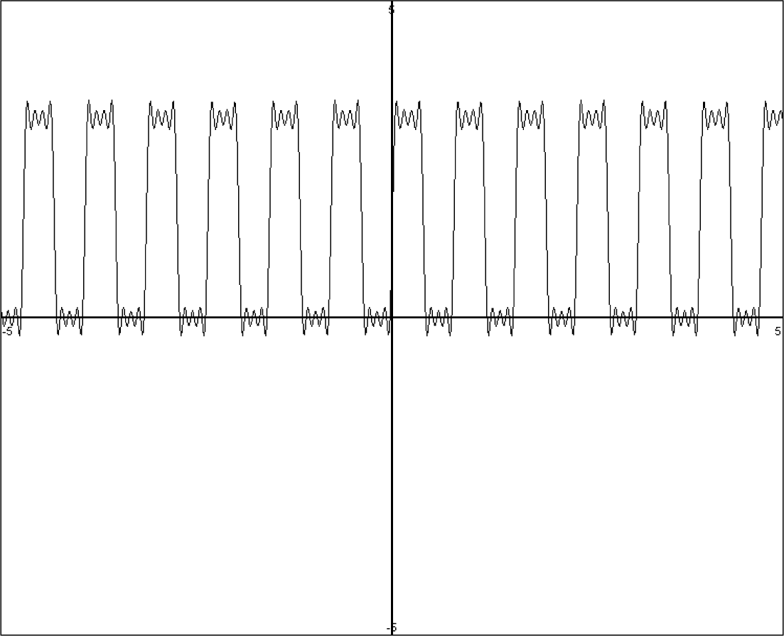
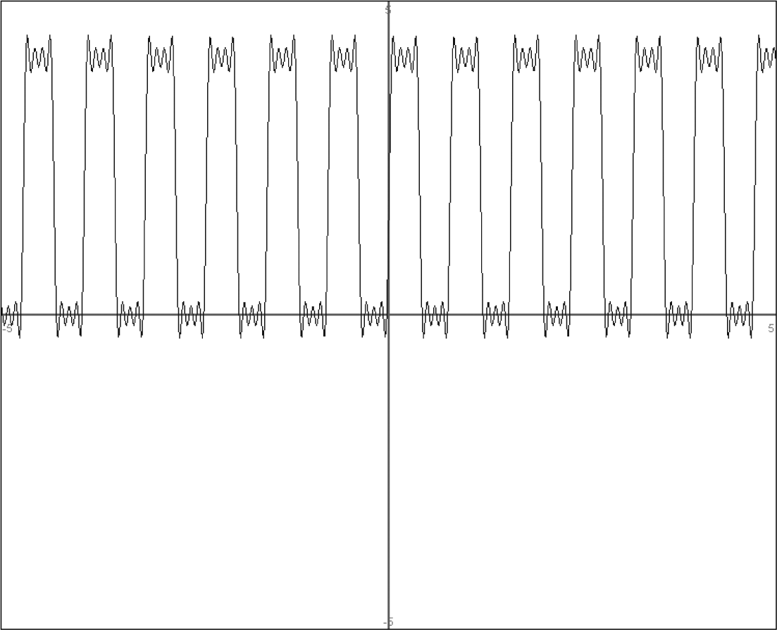
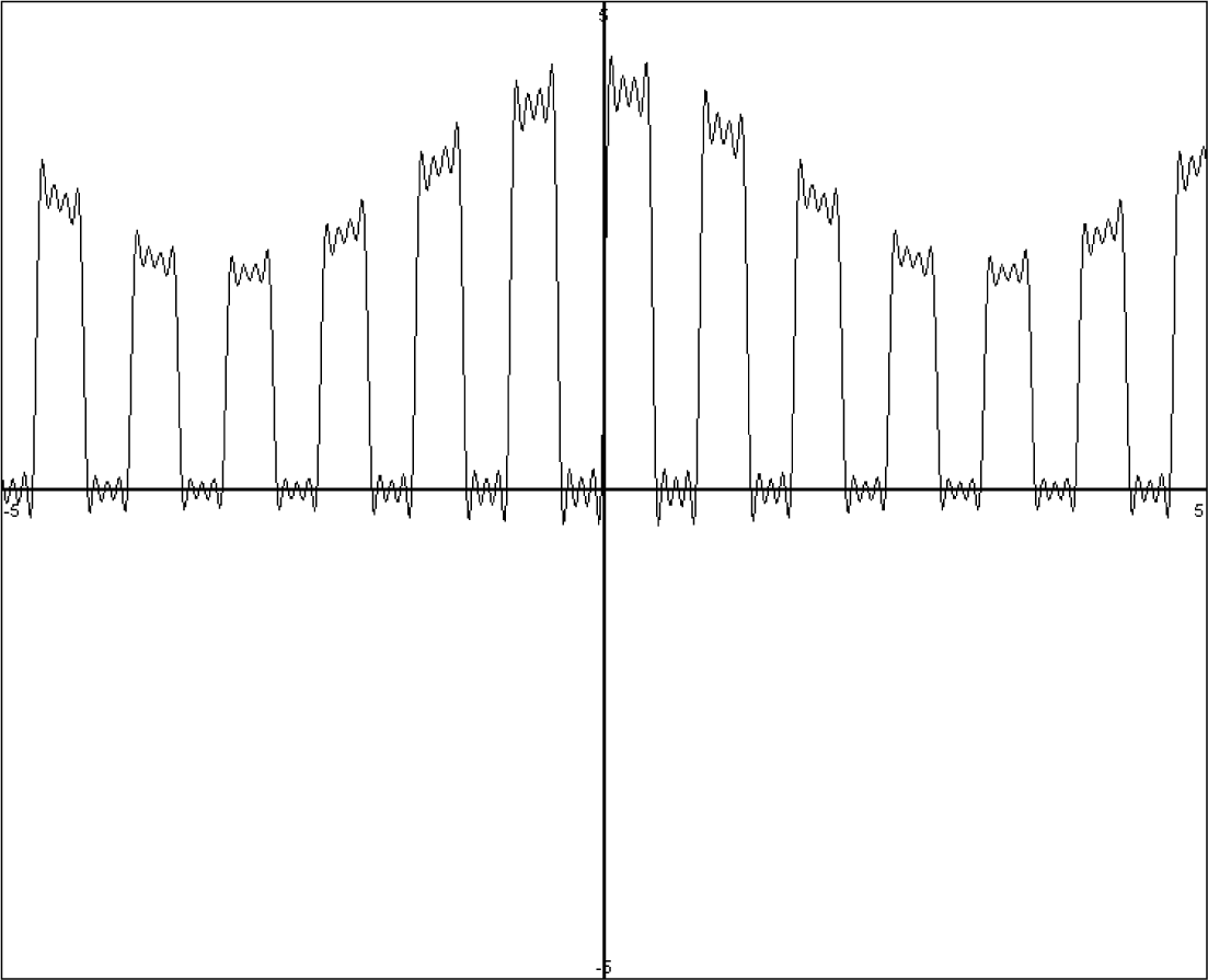
Now, if we replace V with a voltage source that has both DC and alternating-current (AC) voltages, we can produce a pulse amplitude modulation, as seen in Figure 4-11.
FIGURE 4-11 Pulse-amplitude-modulated signal.
Thus the output waveform shows amplitude modulation of pulses, which, although they do not exactly resemble the sinusoidal AM signal in Figure 4-3, nevertheless produce amplitude-modulated (AM) signals at the CW signal’s frequency and harmonics (e.g., mainly the odd-order harmonics shown in Figure 4-11. Note that the waveform in Figure 4-11 also resembles a demodulated AM signal, such as a half-wave-rectified AM signal. This also would mean that this waveform also would contain the “audio” or modulating signal as well, which is true.
Thus the pulse-amplitude-modulated signal from Figure 4-11 is actually made up of many signals—the audio signal, the amplitude-modulated signal of the CW signal, and the harmonics of the amplitude-modulated CW signal.
Thus, if the CW carrier is at 535 kHz and the modulating or audio signal is at 1 kHz, the pulse-amplitude-modulated waveform contains a 1-kHz signal, an AM signal at 535 kHz modulated at 1 kHz, and at least an AM signal at 1,605 kHz also modulated at 1 kHz.
So now let’s look at Figure 4-5 again.
Parts List
• C1, C3: 0.001 μF
• C2: 0.0018 μF
• C4: 470 pF
• C5, C6, C7: 0.01 μF
• C8, C9, C10, C11, C12: 1 μF, 35 volts
• R1: 1,200 ![]()
• R2, R12: 1-k![]() multiturn pot
multiturn pot
• R3, R11: 100 ![]()
• R4: 100 k![]()
• R5: 1 k![]()
• R6, R7, R10: 4,700 ![]()
• R8, R9: 20 k![]()
• R13: 1,800 ![]()
• U1: 74HC14
• U2: 74HC05
• Vreg 1: LM7805 5-volt positive regulator
• L1: 330 μH
With the exception of the 455-kHz band-pass filter consisting of R8, L1, C4, C2, R9, and R10, we have two nearly identical circuits for the CW generator and AM modulator. So we will start with the 535-kHz CW generator. A Schmitt trigger oscillator is formed from U1A, C1, R1, and R2. The frequency is adjusted via R2, which is measured with a frequency counter at pin 2 of U1A or its buffered output at R3. As stated earlier, the frequency can be calibrated to 535 kHz via a frequency counter by grounding one lead of the frequency counter and connecting the other lead to R3.
The 535-kHz CW pulse signal is sent to the input of an open collector inverter U2A pin 1, which has a pull-up or load resistor R6 at the pin 2 output. The actual biasing voltage for R6 is provided through a filtered version of the output of the audio oscillator circuit (Schmitt trigger oscillator) U1E, R4, and C2. R5 and C8 provide a filtered version of a pulse signal, which is a triangle waveform, to act as a (modulating) voltage source for R6. Since the triangle waveform varies, the output at pin 2 of U2A provides a pulse-amplitude-modulated signal at 535 kHz and 1,605 kHz with about a 1-kHz modulating frequency. Finally, a capacitor C7 is connected to pin 2 of U2A to provide an output signal via a short-wire (e.g., <12 inches) antenna to a radio for testing.
Similarly, the 455-kHz CW oscillator circuit consisting of U1F, C3, R13, and R12 produces a pulse waveform. Variable resistor R12 is adjusted to 455 kHz with a frequency counter connected to pin 12 of U1F or R11. The 455-kHz CW pulse waveform is connected to inverter U2F’s input pin 13, and the output of U2F’s pin 12 is connected to a load or pull-up resistor R7. A modulating triangle waveform at 1 kHz provides a varying-voltage source to R7, and thus the output of U2B pin 12 generates a pulse-amplitude-modulated waveform at 455 kHz, 910 kHz, and 1,365 kHz with a modulating frequency of about 1 kHz. The output is also connected via capacitor C6 to a short-wire (e.g., <12 inches) antenna.
A parallel resonance band-pass filter formed by R8, L1, C2, C4, R9, and R10 is also connected to pin 12 to provide a sinusoidal 455-kHz amplitude-modulated (AM) signal at R10. The signal from R10 will be used for aligning the IF amplifiers for the superheterodyne radios later.
If a frequency counter is not available, an alternate way of adjusting R12 would be to place the short-wire antenna from C6 near a radio (with a digital readout) that is tuned to 910 kHz. Then adjust R12 until a 1-kHz tone is heard loudest on the radio.
Similarly, R2 is adjusted by placing the wire antenna connected to C7 near a radio. Tune the (digital readout) radio to 1,070 kHz, which is twice 535 kHz. Adjust R2 until a 1-kHz tone is heard loudest on the radio.
Alternate Circuits
With a little more complexity, the 455-kHz and 535-kHz circuits can be done without having to adjust for the correct frequencies. Crystals and ceramic resonators are used instead, and these components are quite stable and accurate in frequency generation.
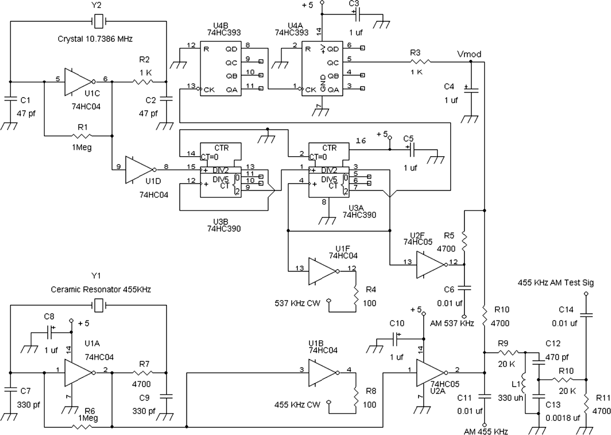
Figure 4-12 shows that the Schmitt trigger oscillators have been replaced with a crystal oscillator and digital dividers and a ceramic resonator oscillator. The 1-kHz modulating or audio oscillator stays in this design but can be replaced with a digital frequency divider to produce modulating tone near 1 kHz.
FIGURE 4-12 Test generator using a crystal and resonator.
Parts List
• C1, C2: 47 pF
• C3, C4, C5, C8, C10: 1 μF, 35 volts
• C6, C11: 0.01 μF
• C7, C9: 330 pF
• C13: 0.0018 μF
• R1, R6: 1 M![]()
• R2, R3: 1 k![]()
• R4, R8: 100 ![]()
• R5, R7, R10, R11: 4,700 ![]()
• R9, R10: 20 k![]()
• U1: 74HC04
• U2: 74HC05
• U3: 74HC390
• U4: 74HC393
• Y1 resonator: 455 kHz
• Y2 crystal: 10.738 MHz
• L1: 330 μH
The generator circuit in Figure 4-12 produces waveforms at 455 kHz and 537 kHz along with their harmonics by using precision resonators in place of the RC Schmitt trigger oscillators from the previous design. Because of the precise frequency generated in this design, no adjustment is necessary with a frequency counter or with a radio. Also, the frequencies 455 kHz and 537 kHz are stable even if the supply voltage varies by plus or minus 20 percent. After this circuit is built, one can confirm that there are AM signals at 455 kHz, 910 kHz, 1,365 kHz, 537 kHz, and 1,611 kHz.
The 455-kHz signal is generated by U1A, an inverter biased up as a high-gain amplifier via resistor R6. In order for oscillation to occur, there must be a 180-degree phase shift from the R7-C9 low-pass filter, the 455-kHz ceramic resonator, and C7. The R7-C9 low-pass filter has a cutoff frequency at about 100 kHz, which ensures by 455 kHz that there are at least 77 degrees of phase shift including the propagation delay of the inverter gate. The ceramic resonator acts like an inductor to resonate with its internal series capacitance within the ceramic resonator and with external capacitor C7. Thus the ceramic resonator with C7 forms a phase-shift network capable of 90 degrees of phase shifting at resonance (455 kHz) and more than 90 degrees just slightly off resonance because of its very high Q.
The output of the 455-kHz oscillator (U1A pin 2) is connected to the input of the pulse-amplitude-modulator circuit U2A pin 1, which has an open-drain output at pin 2 of U2A (see Figure 4-7 and its description for an explanation of a pulse amplitude modulator circuit).
To produce a precise frequency at the low end of the AM band, a 10.7386-MHz crystal was chosen to eventually produce a 537-kHz signal. An 11.00-MHz crystal can be used in place of the 10.7386-MHz unit as well, but the resulting frequency, when divided down, will be 550 kHz instead, a little higher than 537 kHz.
The crystal oscillator works similarly as the ceramic resonator circuit. An inverter, U1C, is biased as a high-gain amplifier via resistor R1. R2 and C2 are for a low-pass circuit with a phase shift of about 70 degrees at 10.738 MHz. The inverter itself has a propagation delay of about 8 ns, which is about 30 degrees of (lagging) phase shift at 10.738 MHz. The remaining (80 or so degrees) of phase shift is produced by the crystal’s internal equivalent inductance and series capacitance inside and with external capacitor C1. The output of the inverter is connected via U1D to a decade frequency divider U2B (74HC390). The 74HC390 decade divider integrated circuit has two divide-by-10 sections. And each divide-by-10 section has a divide-by-2 and a divide-by-5 circuit. The 10.7386-MHz signal is divided by 10 to provide 1.0738 MHz and then divided by 2 to produce a 537-kHz square-wave pulse signal into pulse amplitude modulator U2F (via input pin 13 of the 74HC05), which is an open-drain output inverter. The output of U2F at pin 12 generates an AM signal via C6.
Also, the modulating signal is produced by frequency dividing down from the 10.7386-MHz crystal to generate an 839-Hz waveform at pin 5 of the 74HC393 counter. This is done by dividing the 537-kHz signal from pin 3 of the 74HC390 by 5 via its second divide-by-5 circuit at pin 7. The output signal (537 kHz/5 or 107.4 kHz) at pin 7 of the 74HC390 counter is further divided by 128 via binary counter/divider circuit 74HC393, U4B cascading to U4A to produce an 837-Hz square wave at pin 5 of the 74HC393 counter. Thus the modulating waveform is a triangle wave at 839 Hz across C4, which feeds into the load resistors R10 and R5 to provide pulse amplitude modulation at 455 kHz and 537 kHz, respectively.
