Chapter 7
A Low-Power Regenerative Radio
When I suggested writing a chapter on regenerative radios, I thought this was going to be a piece of cake. It had to be easy, right? Just add some positive feedback to the system, and magically you get higher gain and selectivity. And after all, I had already designed a vacuum-tube version without a problem back in 2007 that had been featured in EDN Magazine on the Web (www.edn.com/blog/Designing_Ideas/41377-A_super_het_radio_runs_5_years_on_a_C_cell_plus_a_pentode_radio.php).
It turns out that my first regenerative radio was designed with a little luck. Yes, luck sometimes plays a part in successful designs.
However, in trying to duplicate that success from a pentode vacuum tube to transistors—well, that’s a different story. The pentode tube design had just the correct amount of transconductance, the antenna coil chosen received the amplitude-modulated (AM) stations with good signal strength, and the number of turns added to the antenna coil for regeneration resulted in a simple high-performance radio that did not go into premature oscillation. One may say that out of beginner’s luck I hit the perfect triad in my first design of a vacuum-tube regenerative radio.
For the transistorized version, the transconductance is much higher than in the pentode, the antenna coil is less sensitive than the one in the pentode, and the number of turns used for regeneration in the antenna coil also was different. So the first few versions of the transistorized regenerative radio actually failed—yes, they failed.
In the following sections of this chapter, some of best features of regenerative radios will be stated, some of the problems encountered will be mentioned, and finally, solutions to these problems will be presented. For now, let’s see what a regenerative radio ideally is supposed to do.
Improving Sensitivity by Regeneration
In Chapter 6 on reflex radios we saw that a single transistor can function as a radio frequency (RF) and audio frequency (AF) amplifier at the same time. But the RF amplification factor of this transistor is fixed by the biasing current of its collector (see Figure 6-3). The direct-current (DC) bias voltage across resistor R2 determines the transconductance of the transistor, and therefore, its gain is fixed.
For regenerative radios, we try to feed back part of the RF energy of the RF amplifier to be reamplified without running into oscillation. This is very tricky because one wants the highest gain possible but also a lack of oscillation within the RF amplifier. Also the leads of the secondary may have to be reversed. Refer to the note at the end of this chapter.
Figure 7-1 presents a “sketch” of a possible transistorized regenerative radio.
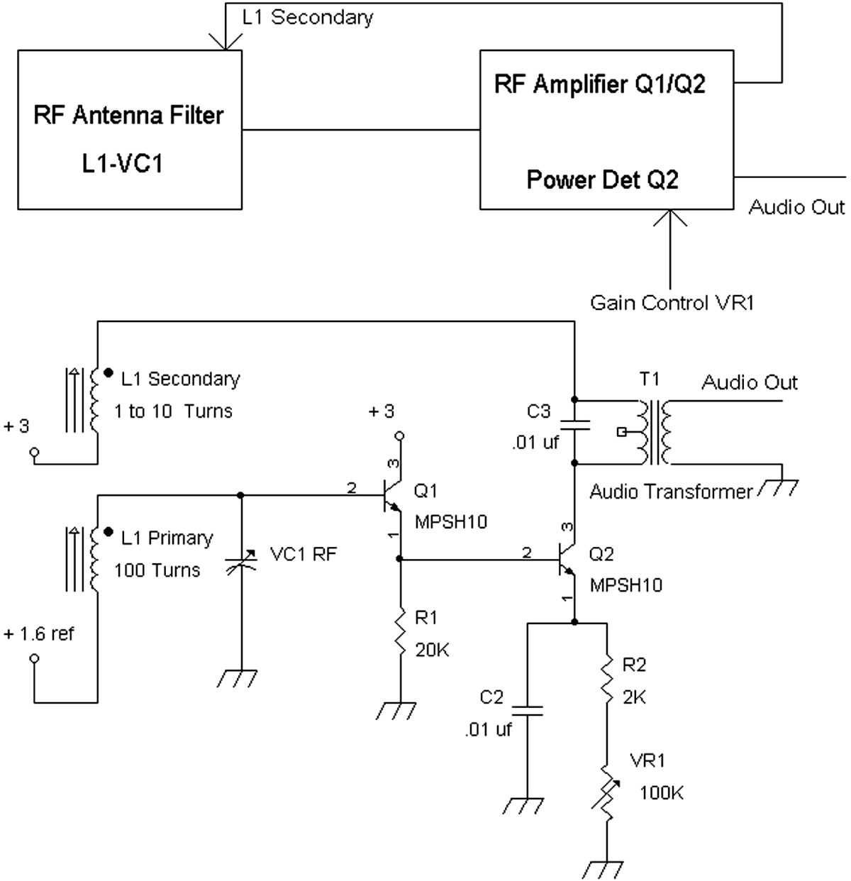
FIGURE 7-1 Block diagram and schematic of a “possible” design for a regenerative radio.
In the figure, the primary of antenna coil L1 is connected to an RF amplifier circuit consisting of Q1 and Q2. Q1 is an emitter follower amplifier designed to give near-unity gain while also providing a high-impedance input resistance for L1’s primary, which will not load down or degrade the Q of the antenna coil. The secondary of L1, which has a smaller number of turns compared with the primary of L1, is used differently in tunable radio-frequency (TRF) radios and reflex radios. Here the secondary winding of L1 is connected to the amplifier output of Q2 to magnetically induce some of the amplified RF signal back to the antenna coil. The secondary winding of the coil is not reversible, so positive feedback occurs only when the windings are connected in the correct manner. If connected in any other manner, negative feedback occurs, and the gain cannot be increased as desired.
The amount of RF signal fed back to the antenna coil is related to how variable resistor VR1 is set. The lower the resistance set to VR1, the higher is the DC collector current of Q2, which increases the gain of the Q2 RF amplifier. Conversely, with VR1 set to a maximum resistance value, a minimum DC collector current is set for Q2, thus setting the gain of the RF amplifier to a minimum. Thus VR1 controls the amount of positive feedback to the antenna coil. The more positive feedback sent back to the antenna coil, L1, the higher is the overall gain of the system. At some point, the RF amplifier Q1 and Q2 will oscillate when VR1 is set to a gain that is sufficient to induce oscillation.
In Figure 7-1, Q2 also works as an AM detector by being a power detector. With a sufficient RF signal level into the base of Q2, power detection or AM demodulation occurs. The audio transformer T1 then extracts the audio signals (e.g., demodulated AM signals).
In operating a regenerative radio, one turns the regeneration control below the threshold of oscillation and then tunes for the stations desired. Once a station is tuned in, turn up the regeneration control until gain is increased, but back off the regeneration as soon as an oscillation is heard (e.g., a whistling or squealing sound).
Improving Selectivity by Q Multiplication via Regeneration
The Q determines the selectivity of an inductor capacitor circuit. Selectivity can be determined by the bandwidth of a tank circuit. The narrower the bandwidth of a resonant circuit, the higher is the selectivity. One measurement of bandwidth is determined by tuned frequency divided by Q.
Thus, if a station is tuned to 1,000 kHz and the Q of the antenna coil is 50, the bandwidth is 1,000 kHz/50 or 20 kHz.
However, AM stations are spaced 9 kHz or 10 kHz apart depending on what part of the world you are in. Thus a bandwidth of 20 kHz theoretically can receive two stations that are adjacent to each other. If the antenna coil has a Q of 100, the bandwidth of the antenna coil variable capacitor tank circuit is 10 kHz, which would be a minimum requirement to separate channels from each other.
In some cases, a Q of 100 is achievable for a particular antenna coil. But getting a Q factor of 200 out of an antenna coil is rare. A limitation on the Q of a coil, antenna coil, or inductor is the internal coil resistance. For example, a typical coil may have a coil resistance of from less than 1 ![]() to at least 10
to at least 10 ![]() . Therefore, one way to effectively reduce or at least partially null or cancel out the internal coil resistance is to provide a negative resistance in parallel with the coil. This negative resistance is generated by an active-amplifying device such as a transistor along with applying positive feedback.
. Therefore, one way to effectively reduce or at least partially null or cancel out the internal coil resistance is to provide a negative resistance in parallel with the coil. This negative resistance is generated by an active-amplifying device such as a transistor along with applying positive feedback.
What happens is the amplifying device pumps energy back (via positive feedback) into the tank circuit to overcome the resistive loss. When a short pulse excites an inductor capacitor tank circuit, the tank circuit will “ring” at its resonant frequency but will decay and fail to ring after a period of time. The Q multiplier effect from a positive-feedback circuit pumps energy back to the coil to sustain a longer ringing effect when excited by a short pulse.
Thus the Q multiplier increases the original Q of the coil by a factor that is determined by the amount of positive feedback applied. With no positive feedback, the Q of the coil is still the original Q. The more positive feedback is applied, though, the higher is the multiplying effect on the original Q of the coil. (There will be a follow-up on the subject of Q in the later chapters of this book such as Chapters 17 and 20.)
Design Considerations for a Regenerative Radio
Two specific characteristics are needed to design a regenerative radio. They are:
1. The RF signal that is being amplified must be “strong” enough to work on its own without positive feedback to raise the amplitude level. That is, if the RF signal is too small to begin with, trying to raise its level via positive feedback may lead to oscillation.
2. The positive feedback must be controllable such that the gain can be raised easily while not causing oscillation of the RF amplifier.
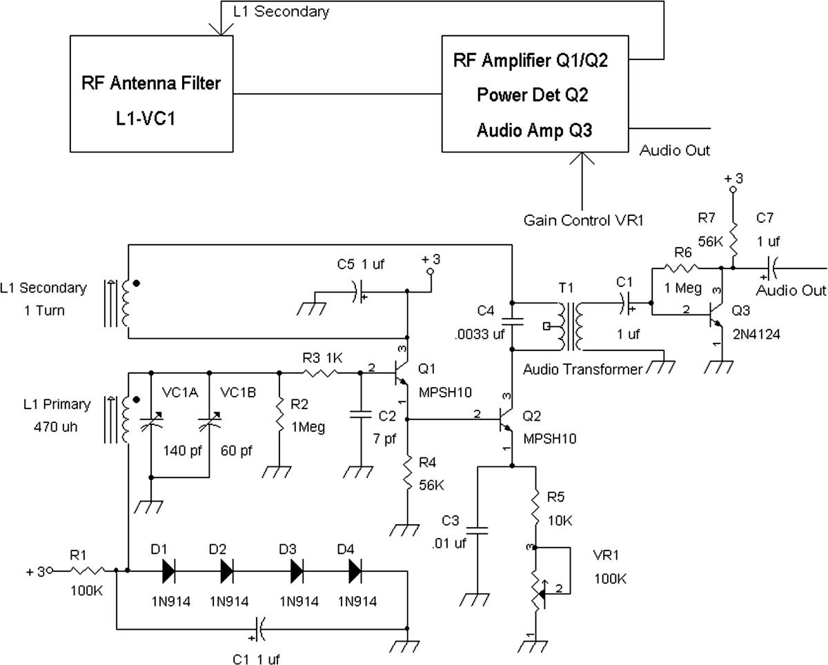
If you take a look at Figure 7-2, you will see a tickler oscillator circuit, which looks like a regenerative radio.
In the figure, a resonant circuit is formed by the L1 primary and VC1, which resonates at a high impedance with 0 degrees of phase shift. The resonant circuit is amplified by Q1 and Q2, with output current from Q2 fed to the L1 secondary. Current flowing into the L1 secondary (10 turns) creates a positive-feedback condition, which causes a sustained oscillation. Any RF signal picked from the L1 primary winding is now small compared with the continuous-wave (CW) signal it is generating at the base of Q1 via oscillation. Thus the RF signal is basically “washed out” by the oscillation signal.
For a larger picture of what’s going on, let’s take a look at Figure 7-1 again. Note that the number of turns on L1’s secondary winding is in a range of 1 to 10 turns. The reason is that when the gain control is set by changing the gain of the RF amplifier of Q2 via variable resistor VR1, there will be a “sweet” or optimal number of turns on L1’s secondary. This optimal number of turns on L1 allows the positive-feedback regenerative system to achieve a balance between having Q2 provide further amplification of the RF signal (without oscillation) and also providing Q multiplication to increase the Q or selectivity of L1. For example, if the number of turns is too many, the positive-feedback regenerative system will break into oscillation before the received signal can be demodulated in a satisfactory manner.
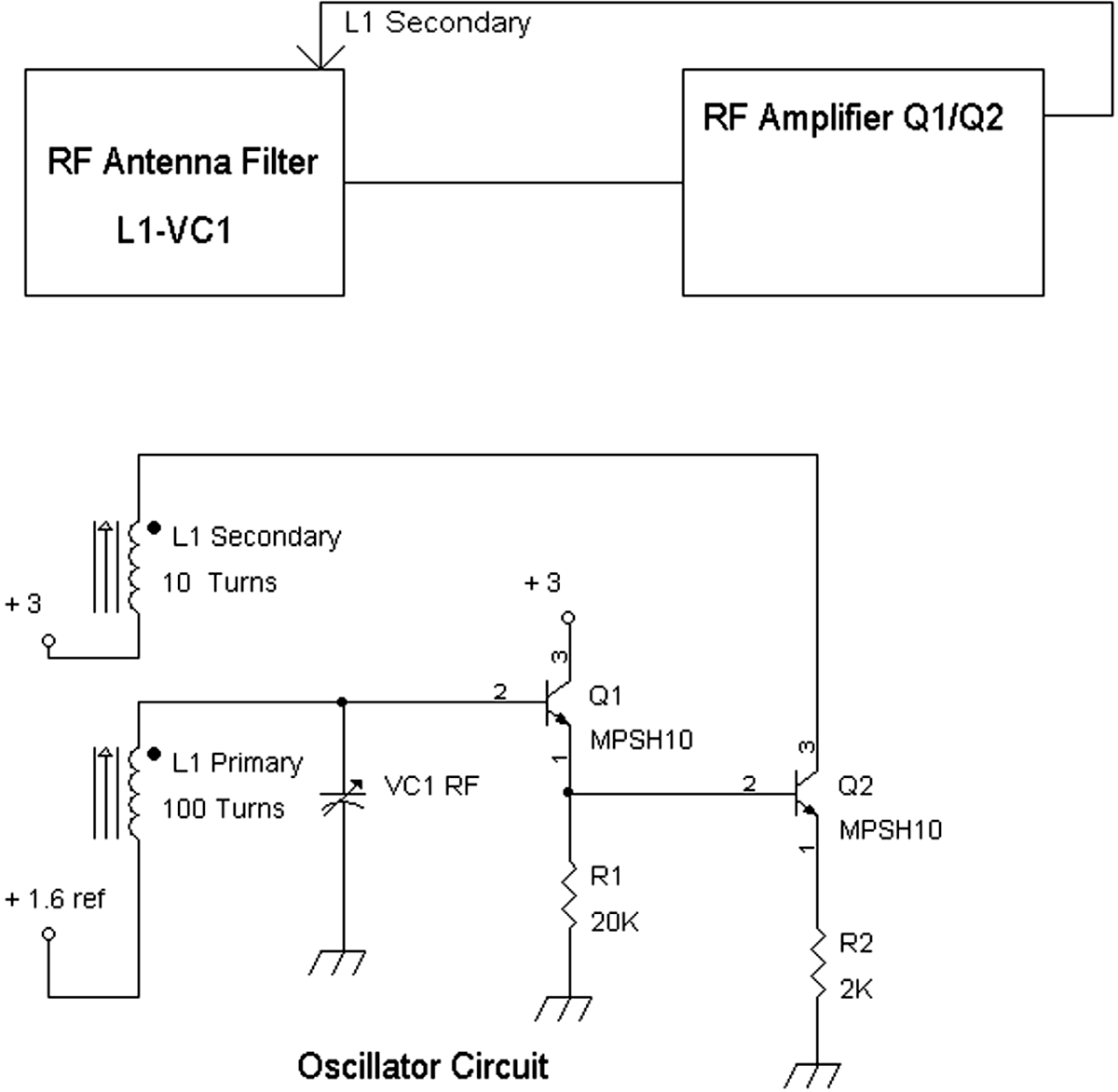
FIGURE 7-2 Block diagram and schematic of an oscillator circuit that resembles a regenerative radio circuit.
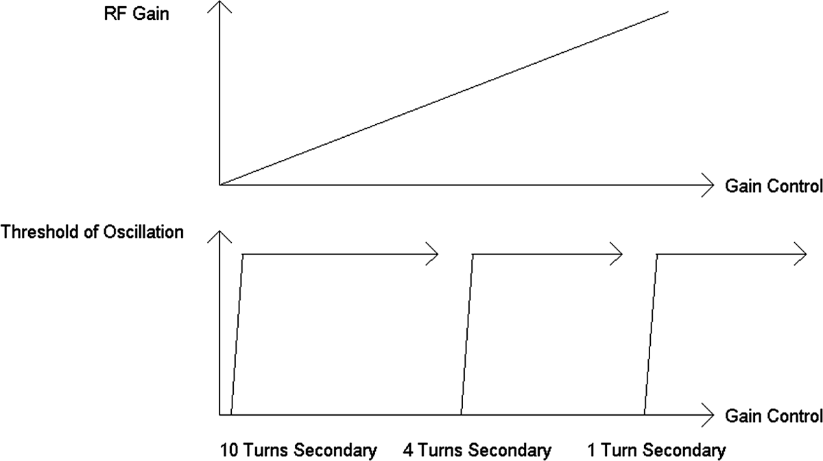
Figure 7-3 shows the relationship of the RF amplifier’s gain and threshold of oscillation as a function of the gain control setting. The top drawing in the figure shows the relationship of the RF gain in an amplifier such as the voltage gain of Q2 in Figure 7-1. As the gain control VR1 is adjusted for minimum resistance, the RF gain is increased via increasing the DC collector current of Q2, which also increases regeneration or the amount of positive feedback.
FIGURE 7-3 Relation of the threshold of oscillation and the RF gain based on the number of secondary winding turns.
However, as the gain control is adjusted for increased RF gain, the RF amplifier itself will start to oscillate. Thus, at the bottom of the figure we see that for 10 turns on the antenna coil L1 of Figure 7-1, oscillation occurs even when the RF gain is low. Under this condition, the overall gain of the RF amplifier is insufficient to raise the incoming or received RF signal to a high enough level for demodulation because oscillation breaks in too early. Once the RF amplifier breaks into oscillation, amplification of the RF signal received from the antenna coil is too low or not useful.
It should be noted that many commercially made antenna coils have a secondary winding of 10 or more turns. Thus, when these antenna coils are tried in the circuit of Figure 7-1, oscillation breaks in much too early before the RF signal can be amplified sufficiently for demodulation. If the antenna coil has four turns for its secondary on L1 of Figure 7-1, then we see from the bottom drawing of Figure 7-3 that there is some useful voltage gain before oscillation starts. And if just one turn of wire is wrapped around the antenna coil, we see that a much larger voltage gain can be provided to amplify the RF signal from the antenna coil before the regeneration (via increasing the gain of Q2) breaks into oscillation. Thus the key to designing a successful regenerative radio is to first have sufficient RF gain to allow demodulation of the AM signal and then second to have the capability of increasing the RF gain, which includes adding positive feedback to further increase the RF gain of the system while also increasing the effective Q or selectivity of the antenna coil without oscillation occurring.
So here is a first somewhat successful transistorized regenerative radio using an internal antenna.
Parts List
• C1, C5, C6, C7: 1 μF, 35 volts
• C2: 7 pF or 6.8 pF
• C3: 0.01 μF
• C4: 0.0033 μF
• R1: 100 k![]()
• R2, R6: 1 M![]()
• R3: 1 k![]()
• R4, R7: 56 k![]()
• R5: 10 k![]()
• VR1: 100 k![]()
• T1 audio transformer: 10 k![]() primary, 10 k
primary, 10 k![]() or 7 k
or 7 k![]() secondary
secondary
• L1 antenna coil: 470 μH with 1 turn wrapped
• VC1 two-gang variable capacitor: 140 pF, 60 pF
• D1, D2, D3, D4: 1N914
• Q1, Q2: MPSH10
• Q3: 2N4124 or 2N3904
This was really the first circuit that worked in a similar way to the pentode regenerative radio featured in EDN Magazine. The trick here was that only one turn was used for the secondary winding to provide the positive feedback for regeneration. And that one turn of wire [e.g., 30 American Wire Gauge (AWG)] was located in the center of L1’s primary winding.
Diodes D1 to D4 form a voltage reference of about 1.6 volts to 2.0 volts for providing a DC bias voltage to Q1. Resistor R3 (1 k![]() ) and capacitor C2 form a network to ensure that Q1 does not oscillate parasitically. As seen here, the RF signal is picked up by the antenna coil L1 primary and is connected to Q1, a near-unity gain amplifier with high-resistance input, so as not to load down the Q of L1’s primary winding.
) and capacitor C2 form a network to ensure that Q1 does not oscillate parasitically. As seen here, the RF signal is picked up by the antenna coil L1 primary and is connected to Q1, a near-unity gain amplifier with high-resistance input, so as not to load down the Q of L1’s primary winding.
Q2 serves two purposes: One is to amplify the RF signal from L1’s primary winding and send back the signal to L1 via the one-turn secondary winding for regeneration or positive feedback. The second purpose of Q2 is to provide demodulation of the AM signal via power detection. When AC signals of greater than 10 mV peak are coupled to a common emitter amplifier such as Q2, distortion occurs in a manner that demodulates AM signals.
Gain (or regeneration) control variable resistor VR1 is used to set the amount of regeneration such that the positive feedback increases the RF gain and increases the Q of L1. The audio signals are extracted from Q2 via audio transformer T1’s primary. Capacitor C4, which is across the primary of T1, filters out the RF signal from Q2, and C4 also provides an RF signal path to the secondary winding of L1.
Audio amplifier Q3 is a common emitter amplifier that further amplifies the demodulated AM signal. This audio amplifier was needed because of the very low levels of audio signals from power detector Q2.
The radio design in Figure 7-4 was one of the first transistorized regenerative radios that finally worked for me—after a few other tries.
FIGURE 7-4 Block diagram and schematic of a regenerative radio using a secondary winding of one turn around the primary winding.
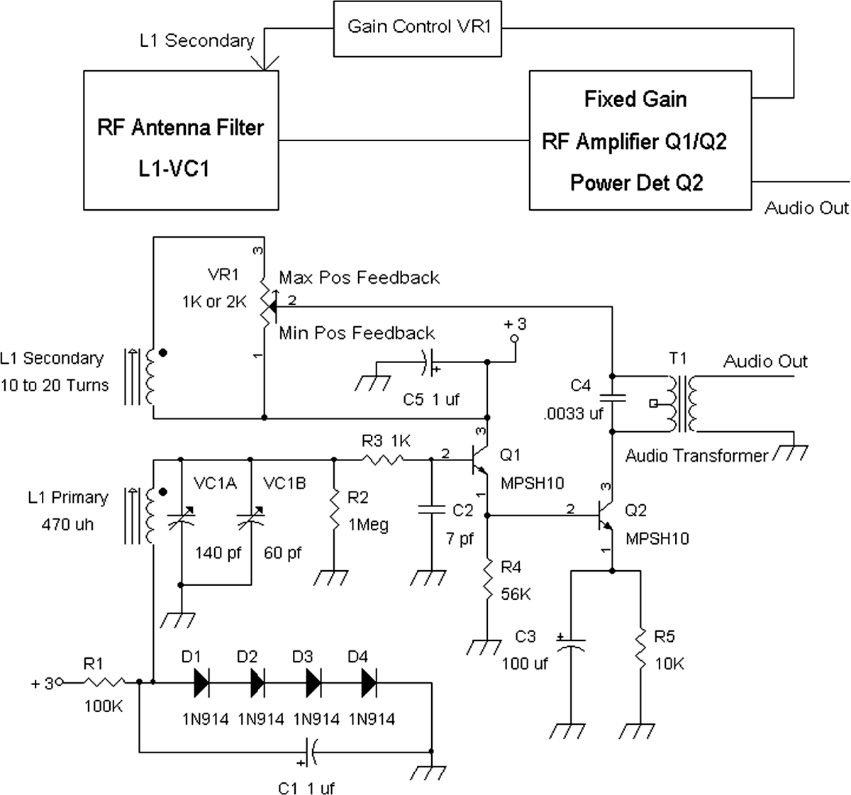
But what if one does not want to go through the trouble of winding wire around the antenna coil and instead wants to use the existing secondary winding? Well, there is a way to use the existing secondary winding. And two methods will be shown.
Figure 7-5 shows almost the same circuit as Figure 7-4, but it uses the existing secondary winding of 10 to 20 turns.
Parts List
• C1, C5: 1 μF, 35 volts
• C2: 7 pF or 6.8 pF
• C3: 100 μF, 16 volts
• C4: 0.0033 μF
• R1: 100 k![]()
• R2: 1 M![]()
• R3: 1 k![]()
• R4: 56 k![]()
• R5: 10 k![]()
• VR1: 1 k![]() or 2 k
or 2 k![]()
• T1 audio transformer: 10 k![]() primary, 10 k
primary, 10 k![]() or 7 k
or 7 k![]() secondary
secondary
• L1 antenna coil: 470 μH primary
• VC1 two-gang variable capacitor: 140 pF, 60 pF
• D1, D2, D3, D4: 1N914
• Q1, Q2: MPSH10
In this version, VR1, the regeneration control, is connected across the secondary winding of L1. The regeneration signal current from Q2 is fed to the wiper of VR1, which can divert this signal current to the +3-volts supply voltage and/or to the secondary winding. That is, part of the signal current from Q2 can be fed to the secondary winding of L1 in a variable manner. This variable signal current into the secondary winding allows for good control of the regeneration. For example, if the wiper of VR1 is set toward pin 3 of VR1, most of the regeneration signal current will be diverted to the secondary of L1. However, if the wiper of VR1 is set toward pin 1 of VR1, most of the regeneration signal will be diverted to the +3-volts supply, leaving little or no signal current to the secondary winding. And setting the wiper of VR1 in between will send a fraction of the regeneration signal to the secondary winding and a fraction of this regeneration signal to the +3-volts supply.
Note that the +3-volts supply is also an AC signal ground. That is, other than having +3 volts DC, the +3-volts rail has no AC signals on it because AC-wise, it is the same as ground. Also note that Q2 now is a fixed-gain amplifier and does not have a variable resistor, as seen in Figure 7-4.
It should be noted that in the prototype, VR1 is a multiturn potentiometer. The audio signal from T1 may be amplified further by using the Q3 amplifier circuit from Figure 7-4.
FIGURE 7-5 Block diagram and schematic of a regenerative radio using a potentiometer to adjust and control the amount of positive feedback.
By placing a variable resistor across the secondary winding of L1, the primary winding is loaded down with an equivalent parallel resistor of (VR1’s value) × N × N, where N is the turns ratio of primary to secondary windings. Thus, if N = 20:1, N × N = 400, VR1 = 1 k![]() , and the equivalent parallel resistor is 400 × 1 k
, and the equivalent parallel resistor is 400 × 1 k![]() , or 400 k
, or 400 k![]() . Should N = 10:1, the equivalent parallel resistor is 100 k
. Should N = 10:1, the equivalent parallel resistor is 100 k![]() .
.
Depending on the turns ratio of the antenna coil, the value of VR1 can affect Q. Thus the last regenerative radio design shown will not affect the Q of the antenna coil by not loading the secondary winding with resistance while allowing a range of number of turns on the secondary winding for regeneration. When all the previous designs (Figures 7-4 and 7-5) were analyzed and assessed for performance, there seemed to be something missing. In Figure 7-4, one had to experiment in winding a number of turns to hit the optimal spot in terms of RF gain before oscillation broke out. In Figure 7-5, there was the potential problem of loading down the Q of the antenna coil.
Certainly a higher-performance design could be made, but how? It occurred to me that maybe I could separate the regeneration from the RF amplifier and have a separate second-stage amplifier to increase the RF level. The block diagram for this idea is shown in Figure 7-6.
By using a dedicated transistor Q3 for the positive-feedback circuit, the regeneration can be controlled for a range of turns on the secondary of the antenna coil, whereas a separate gain stage in Q2 can further amplify the signal for even better sensitivity. This scheme worked pretty well considering that only a 2-inch-long ferrite antenna coil was used and the radio in the San Francisco Bay Area picked up radio station KNX (1,070 kHz) from Los Angeles.
Parts List
• C1, C3, C9, C10: 1 μF, 35 volts
• C2: 7 pF or 6.8 pF
• C4, C5, C6, C11, C12: 0.01 μF
• C7: 0.15 μF
• C8: 0.0015 μF
• R1: 56 k![]()
• R2: 1 M![]()
• R3, R7, R14: 1 k![]()
• R4, R8: 4,700 ![]()
• R5, R9, R12: 100 k![]()
• R6: 2,200 ![]()
• R10, R13: 10 k![]()
• R11: 20 k![]()
• L1 antenna coil: 470 μH
• VC1 two-gang variable capacitor: 140 pF, 60 pF
• D1, D2: 1N914
• Q1, Q2, Q3: MPSH10
• Q4: MPSH10 or 2N3904
• VR1: 5 k![]()
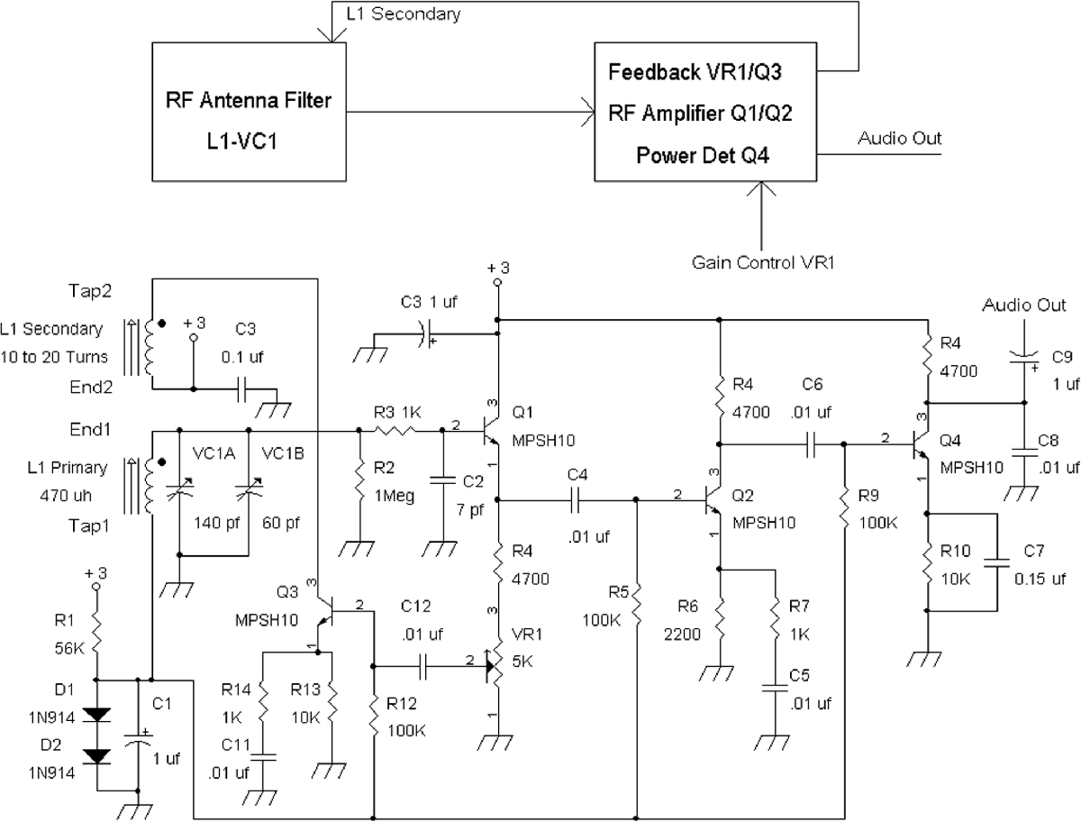
FIGURE 7-6 Block diagram and schematic of a preferred design for a regenerative radio.
RF signals are amplified with near-unity gain from Q1, which has an emitter load resistor of R4 and VR1, the regeneration control. The wiper of VR1 allows for up to 50 percent of the signal from Q1 to be sent to the input of the regeneration amplifier Q3.
Thus, in this design, a separate transistor Q3 is used for providing the regeneration signal back to L1 via the secondary winding. The signal from the collector of Q3 is a current source, which means a high resistance to ground. This high output resistance (e.g., >100 k![]() ) from the collector of Q3 therefore does not load the secondary winding with resistance and thus further allows the antenna coil L1 to retain a high Q.
) from the collector of Q3 therefore does not load the secondary winding with resistance and thus further allows the antenna coil L1 to retain a high Q.
By turning up the signal from VR1, regeneration occurs, and increased RF voltage gain is achieved at the output of Q1’s emitter. The RF signal from Q1 is further amplified by Q2. The output of Q2 then is connected to a power detector Q4, which demodulates the AM signal.
At 3 volts for the supply, this radio drained less than 300 μA. So two D cells should last about 5 years continuously. It should be noted that this radio will work down to 1.4 volts as well. Of course, three vegetable/fruit cells or about four to six solar cells can be used to power this regenerative radio.
![]()
Depending on how the antenna coil is wound, regeneration may or may not occur. Thus, the secondary winding connections should be connected one way or reversed to achieve regeneration. That is, if regeneration does not occur the first time, try reversing the secondary winding’s leads, which should then lead to regeneration or positive feedback of the RF signal.
