
Appendix D
Z-Transform
The z-transform is used for sampled signals. It is analogous to the s-transform used with continuous or analog signals. We shall use xk and yk to represent the input and output signals to a digital filter, respectively. Rather than using differentiators, as analog filters use, the delay function is used instead. The input and output of the IIR (recursive) digital filter is related by the following relationship.
The first term is a sum of coefficient weighted delayed versions of the input (this is the familiar FIR filter expression). The second term is a coefficient weighted sum of the delayed versions of the output, which implies feedback.
The feedback part prevents us from using our earlier method of finite impulse response (FIR) design analysis, described in Appendix B. But again, some smart people figured out a way to map things into the z-domain, where the math becomes simpler. This is an introduction to that technique.
The z-transform is very useful. It can be used to determine the frequency response of an infinite impulse response (IIR) filter. It can also be used to find the coefficients of the IIR filter from the zeros and poles locations, or to do the inverse, to find the poles and zeros of the IIR filter from the coefficients.
The z-transform uses a special exponential function z−i, where z is a complex variable.
The definition of the z-transform of any given sampled time sequence xi is
We can characterize a digital filter by its z-transform, H(z). We will show that
where Y(z) is the z-transform of the output sampled time sequence yk; X(z) is the z-transform of the input sampled time sequence xk.
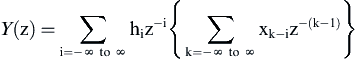
Let us consider a digital filter, with an impulse response of hi. The output of this filter is given by:
where xk is the input sequence (we developed this in the Chapter 5 of FIR filter).
Let us take the z-transform of both xk and yk to see if we can determine H(z):
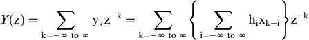
Now we will interchange the order of summation:
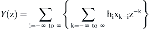
Next remove hi from the inner summation, as it is independent of k:
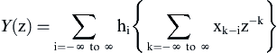
Next, factor z−k into 2 terms:
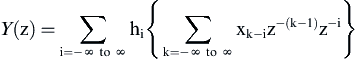
Then remove z−i from the inner summation, as it is independent of k:
The bracket term above is simply X(z).
This demonstrates that Y(z) = H(z) · X(z).
Let us look at this a different way. The filter's response has a z-transform, which is equal to the z-transform of the output sequence yk divided by the z-transform of the input sequence xk, denoted H(z).
By definition, yk equals the impulse response when we set xk equal to an impulse. The z-transform of the impulse function is equal to 1, so the z-transform of the impulse response of the filter is simply the z-transform of the output.
where hi is defined as the impulse response of the filter.
This sounds familiar to frequency response H(ω), and indeed the two are related. The frequency response is contained within the z-transform. The frequency response can be found from the z-transform by replacing z with ejω, or when z is evaluated around the unit circle on the complex z-plane.
With an IIR filter, computing the impulse response sequence hi can often be difficult. The usefulness of the z-transform is that it can be used to compute the frequency response H(ω) without first computing the impulse response hi. The z-transform can be found easily if either the coefficients of the digital filter are available, or the poles and zeros of the digital filter are available. Then take the expression H(z), replace z with ejω, and then evaluate the frequency response over the interval −π < ω < π.
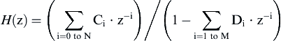
H(z) is simply a function of z. Our goal will be to express H(z) as a function of two polynomials in z, in the form of
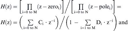
With a bit of algebra, we can then rearrange the polynomials into the following form:
In this form, the coefficients can are available by inspection. Or, if you have the coefficients, you can easily write the z-transform of the filter.
The z-transform can also be arranged in pole—zero format. Remember, by definition, the zeros of the z-transform are the values of z where H(z) = 0 (the roots of the numerator) and the poles of the z-transform are the values of z where H(z) = ∞ (the roots of the denominator).
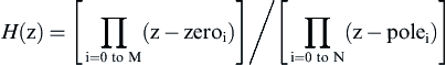
To summarize, if you are given the poles and zeros, you can immediately construct the z-transform using the template above. Although it may take a bit of algebra, the z-transform can be rewritten in summation form to find the coefficients. And evaluating the z-transform in either form over the complex unit circle will give the frequency response of the filter. This is done by substituting ejω for z, and computing over interval –π < ω < π,
As with the s-plane, we can show that pole location on the z-plane is restricted for stability reasons. All poles within the z-plane must lie within the unit circle. Zeros have no restriction on the z-plane.
..................Content has been hidden....................
You can't read the all page of ebook, please click here login for view all page.