
Chapter 23
Introduction to Video Processing
Abstract
The importance of this chapter is on the processing of video. Video signal processing is used throughout the broadcast industry, the surveillance industry, in many military applications and is the basis of many consumer technologies. Video data can be in several formats, which are introduced and explained. Support for both color and black/white video is explained. Important concepts such as color spaces and interlacing/deinterlacing are covered. The primary video interfaces and cabling standards are also introduced. The need for video compression is also covered.
Keywords
Chroma scaling; Color spaces; Deinterlacing; Pixels; Video compression; Video signal processing
Video signal processing is used throughout the broadcast industry, the surveillance industry, in many military applications and is the basis of many consumer technologies. Up until the 1990s, nearly all videos were in analog form. In a relatively short time span, nearly all video technologies have become digital. Virtually all videos are now represented in digital form, and the digital signal processing techniques are used in nearly all video signal processing functions.
The picture element or “pixel” is used to represent each location in an image. Each picture element has several components, and each component is usually represented by a 10-bit value.
23.1. Color Spaces
There are several conventions or “color spaces” used to construct pixels. The broadcast industry originally used black-and-white images, so a video signal contained only luminance (or brightness) information. Later, color information was added to provide for color television and movies. This was known as the chrominance information. The color space formats associated with this is known as YCrCb, where Y is the luminance information, Cr and Cb are the chrominance information. Cr tends to contain more reddish hue color information, while Cb tends to contain more bluish hue color information (Fig. 23.1). Each is usually represented as a 10-bit value. One advantage of this system is that image processing and video bandwidth can be reduced by separating the luminance and chrominance. This is because our eyes are much more sensitive to intensity, or brightness, than to color. So a higher resolution can be used for luminance, and less resolution for chrominance. There are several formats used.

Most broadcast systems and video signals use the 4:2:2 YCrCb format, where the luminance is sampled at twice the rate of each Cr and Cb chrominance. Each pixel, therefore, requires an average of 20 bits to represent, as compared to 30 bits for 4:4:4 YCrCb.
An alternate system was developed for computer systems and displays. There was no legacy of black and white to maintain compatibility with, and transmission bandwidth was not a concern, as the display is just a short cable connection to the computer. This is known as the RGB format, for red/green/blue (Fig. 23.2). Each pixel is composed of these three primary colors and requires 30 bits to represent. Most all televisions, flat screens, and monitors use RGB video, whereas nearly all broadcast signals use 4:2:2 YCrCb video.
These two color spaces can be mapped to each other as follows:

There are other color schemes as well, such as CYMK, which is commonly used in printers, but we are not going to cover this further here.
Different resolutions are used. Very common resolution is the NTSC (National Television System Committee), also known as SD or standard definition. This has a pixel resolution of 480 rows and 720 columns. This forms a frame of video. In video jargon, each frame is composed of lines (480 rows) containing 720 pixels. The frame rate is approximately 30 frames (actually 29.97) per second.
23.2. Interlacing
Most NTSC SD broadcast video is interlaced. This was due to early technology where cameras filmed at 30 frames per second (fps), but this was not a sufficient update rate to prevent annoying flicker on television and movie theater screens. The solution was interlaced video where frames are updated at 60 fps, but only half of the lines are updated on each frame. One frame N, the odd lines are updated, and on frame N + 1 the even lines are updated and so forth. This is known as odd and even field updating.
Interlaced video requires half the bandwidth to transmit as noninterlaced or progressive video at the same frame rate, as only one half of each frame is updated at the 60 fps rate.
Modern cameras can record full images at 60 fps, although there are still many low-cost cameras that produce this interlaced video. Most monitors and flat screen televisions usually display full or progressive video frames at 60 fps. When you see a 720p or 1080i designation on a flat screen, the “p” or “i” stand for progressive and interlaced, respectively.
23.3. Deinterlacing
An interlaced video stream is usually converted to progressive for image processing, as well as to for display on nearly all computer monitors. Deinterlacing must be viewed as interpolation, for the result is twice the video bandwidth. There are several methods available for deinterlacing, which can result in different video qualities under different circumstances.
The two basic methods are known as “bob” and “weave.” Bob is the simpler of the two. Each frame of interlaced video has only one half the lines. For example, the odd lines (1,3,5, … 479) would have pixels, and the even lines (2,4,6, … 480) are blank. On the following frame, the even lines have pixels, but the odd lines are blank. The simplest bob interlacing is to just copy the pixels from the line above for blank even lines (copy line 1 to line 2), and copy the pixels from the line below for blank odd lines (copy line 2 to line 1). Another method would be to interpolate between the two adjacent lines to fill in a blank line. Both of these methods are shown in Fig. 23.3.

This method can cause blurring of images, because the vertical resolution has been effectively halved.
Weave deinterlacing creates a full frame from the separate interlaced frames with odd and even lines. It then copies this frame twice, to achieve the 60 fps rate. This method tends to work only if there is little change in the odd and even interlaced frames, meaning there is little motion in the video. As the odd and even frame pixels belong to different instances in time (1/60th of a second difference), rapid motion can result in jagged edges in the images rather than smooth lines. This is shown in Fig. 23.4.
Both of these methods have drawbacks. A better method, which requires more sophisticated video processing, is to use motion adaptive deinterlacing. Where there is motion on the image, the bob technique works better, and slight blurring is not easily seen. In still areas of the image, the weave method will result in crisper images. A motion adaptive deinterlacer scans the whole image and detects areas of motion, by comparing to previous frames. It will use the bob method in these areas of the frame and use the weave method on the remaining areas of the frame. In this way, interlaced video can be converted to progressive with little loss of quality.

23.4. Image Resolution and Bandwidth
Early televisions used a cathode ray gun inside a fluorescent tube. The gun traversed the screen horizontally from left to right for each line. There was a brief horizontal blanking period, while the gun swung back to the left side of the screen, as indicated by the horizontal sync (HSYNC) signal. After 480 lines, the gun would be at the bottom right corner of the screen. It would swing back to the top left corner to begin a new frame, as indicated by the vertical sync (VSYNC) signal. This time period was the vertical blanking time.
Owing to these blanking periods, the frame size is larger than the image size. For example, in SD definition, the actual image size viewed is 480 × 720 pixels. When blanking times are included, this is as if a 525 × 858 pixel image was sent, with the pixels blanked out, or zeroed, during the extra horizontal and vertical space. This legacy of allowing time for the cathode ray gun to return to the beginning of the video line or frame is still present in video standards today. In digital video and displays, these empty pixels can be filled with what is called ancillary data. This could be a display text at the bottom of the screen, the audio information, data on the program currently being viewed, and so forth. The extra blanking times must be taken into account when determining video signal bandwidths.
Higher definition or resolution, or HD, video formats are now common. HD can refer to 720p, 1080i, or 1080p image resolutions. Popular video resolutions are shown in Table 23.1. Many people are unaware, but often the HD 3 720p video. The quality difference is small, and it requires half the transmission bandwidth to transmit. Most HD flat screens can display 1080p resolution, but this resolution video is normally available only through DVRs or from other in home media sources.
Recently, ultrahigh resolution 4K video support is being made to the consumer market. This increases the frame resolution to 2160 × 3840 or four times greater than 1080p.
Table 23.1
| Image Size | Frame Size | Color Plane Format at 60 frames per second | Bit/s Transfer Rate |
| 1080p × 1920 | 1125 × 2200 | 4:2:2 YCrCb | 2200 × 1125 × 20 × 60 = 2.97 Gbps |
| 1080i × 1920 | 1125 × 2200 | 4:2:2 YCrCb | 2200 × 1125 × 20 × 60 × 0.5 = 1.485 Gbps |
| 720p × 1280 | 750 × 1650 | 4:2:2 YCrCb | 1650 × 750 × 20 × 60 = 1.485 Gbps |
| 480i × 720 | 525 × 858 | 4:2:2 YCrCb | 858 × 525 × 20 × 60 × 0.5 = 270 Mbps |

23.5. Chroma Scaling
Chroma scaling is used to convert between the different YCrCb formats, which have various resolution of color content. The most popular format is 4:2:2 YCrCb. In this format, each Y pixel has alternately a Cr or a Cb pixel associated with it but not both. To convert to the RGB format, 4:4:4 YCrCb representation is needed, where each Y pixel has both a Cr and Cb pixel associated with it. This requires interpolation of the chroma pixels. In practice this is often done by simple linear interpolation or by nearest neighbor interpolation. It can also be combined with the mapping to the RGB color space. Going the other direction is even simpler, as the excess chroma pixels can be simply not computed during the RGB → 4:2:2 YCrCb conversion.
23.6. Image Scaling and Cropping
Image scaling is required to map to either a different resolution, or to a different aspect ratio (row/column ratio). This requires upscaling (interpolation) over two dimensions to go to a higher resolution, or downscaling (decimation) over two dimensions to go to a lower resolution. Several methods of increasing complexity and quality are available such as:
• Nearest neighbor (copy adjacent pixel);
• Bilinear (use 2 × 2 of array of four pixels to compute new pixel);
• Bicubic (use 4 × 4 of array of 16 pixels to compute new pixel); and
• Polyphase (larger array of N × M pixels to compute new pixel).
When filtering vertically over several lines of video, the memory requirements increase, as multiple lines of video must be stored to perform any computations across vertical pixels. The effects of increasing filtering when downscaling can be easily seen using a circular video pattern. Downscaling, like decimation, will cause aliasing if high frequencies are not suitable filtered, as shown in Fig. 23.5.
Upscaling is far less sensitive as downscaling. Bicubic (using a 4 × 4 array of pixels) is sufficient. The effect of performing upscaling by using a smaller array or nearest neighbor is limited to slight blurriness, which is far less objectionable than aliasing.

Cropping is simply eliminating pixels, to allow an image to fit within the frame size. It does not introduce any visual artifacts.
23.7. Alpha Blending and Compositing
Alpha blending is the merging of multiple images. One image can be placed over the top of one image, as shown below. This is known as compositing, a common process used to implement “picture in picture” (Fig. 23.6) functionality.
The more general case is a blending or weighting of the pixels in each image. This is controlled by a factor, alpha (α). This is done on a pixel by pixel basis, for each color as shown.

23.8. Video Compression
Video data is very large, due to two spacial dimensions, high resolution, and requires 60 fps. To store or transmit video, data compression technology is used. This is essential to allow service such as video on demand or streaming video to handheld wireless devices. Video compression is a lossy process—some information is lost. The goal is to achieve as much compression as possible, while minimizing the data loss and restoring same perceptual quality when video is decompressed. This is especially important in fast motion video, such as during televised sports.
Video compression ratios depend on both the compression technology or standard used, and the video content itself. The newer video compression algorithms can deliver better quality, but at a price of very high computational requirements. Video compression processing is almost always done in hardware due to the computational rate, either in field programmable gate arrays (FPGAs) or application-specific integrated circuits (ASICs).
The most popular video compression algorithms are part of the MPEG4 standard. MPEG4 evolved from earlier H.263. At the time of this writing, MPEG4 part 10, also known as MPEG4 AVC or H.264 is mature and has been widely adopted by industry.
As you might guess, video compression is a very complex topic. It involves analysis across both spatial and temporal dimensions and uses complex algorithms. The two images in Fig. 23.7 depict comparative quality of an early version of MPEG4 and quality of the later MPEG4-10, in a video with a high degree of motion. An introduction to this topic will be covered in a subsequent chapter.
23.9. Digital Video Interfaces
There are several common video interfaces, which are used both in broadcast industry and among consumer products. These are briefly described below:

SDI: This is a broadcast industry standard (Fig. 23.8), used to interconnect various professional equipment in broadcast studios and mobile video processing centers (like those big truck trailers seen at major sports events). SDI stands for “serial data interface,” which is not very descriptive. It is an analog signal, modulated with digital information. This is usually connected using a coaxial cable. It is able to carry all of the data rates listed in Table 23.1 and dynamically switch between them. Most FPGAs and broadcast ASICs can interface directly with SDI signals.
DVI: Digital visual interface (DVI) is a connection type commonly used to connect computer monitors. It is a multipin connector carrying separated RGB digitized video information at the desired frame resolution (Fig. 23.9).


HDMI: High definition multimedia interface (HDMI) is also commonly used on computer monitors and on big screen to connect home theater equipment such as flat panels, computers, and DVDs together. Also carrying video and audio information in digital form, HDMI has backward electrical compatibility to DVI but utilizes a more compact connector. Later versions of HDMI support higher video frame sizes, rates, and higher bits per pixel (Fig. 23.10).
DisplayPort: The latest state of the art video interface is DisplayPort. This digital interface uses a packetized protocol to transmit video and audio information. DisplayPort can have 1, 2, 3, or 4 serial differential interfaces to support various data rates and very high resolutions. Each serial interface supports about 5 Gbps data rate. It also uses 8/10-bit encoding, which allows the clocking to be embedded with the data. It also has a compact form factor connector, similar in size to HDMI (Fig. 23.11).


23.10. Legacy Analog Video Interfaces
VGA: Video graphics array connector is used to connect legacy computer monitors. Still common today, it is the familiar multipin “sub-D” connector located on the back or side of many laptop or desktop computers, used to connect to monitors or for laptops to connect to projectors for whole room viewing. This carries separated RGB analog video information at the desired frame resolution (Fig. 23.12).

CVBS: Standing for “composite video blanking and sync,” this is the basic yellow cable used to connect televisions and VCRs, DVDs together. It carries an SD 4:2:2 YCrCb combined analog video signal on a low-cost coax “patch cable” (Fig. 23.13).
S-Video: This is a legacy method used to connect consumer home theater equipment such as flat panels, televisions and VCRs, and DVDs together. It carries analog 4:2:2 YCrCb signals in separate form over a single multipin connector, using a shielded cable. It is of higher quality than CVBS (Fig. 23.14).
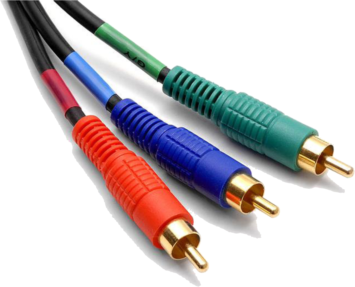
Component Video: This also is legacy method to connect consumer home theater equipment such as flat panels, televisions and VCRs, and DVDs together. It carries analog 4:2:2 YCrCb signals in separate form over a three coax patch cables. Often the connectors are labeled as Y, PB, and PR. It is of higher quality than S-video due to separate cables (Fig. 23.15).


..................Content has been hidden....................
You can't read the all page of ebook, please click here login for view all page.