
Appendix C
Laplace Transform
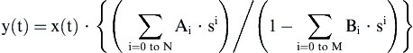
The Laplace transform is used for continuous or analog signals. We shall use x(t) and y(t) to represent the input and output signals to an analog filter, respectively. Rather than use delays, as digital filters use, the differentiator is used instead. The input and output of the analog filter is related by the following relationship.
The first term is a sum of coefficient weighted derivatives of the input, which is analogous to the FIR filter being a sum of weighted delayed inputs. The second term is a coefficient weighted sum of the derivatives of the output, which implies feedback.
These can be difficult functions to evaluate and characterize. Smart people long ago figured out a way to map things into the s-domain using the Laplace transform, where the mathematics becomes much simpler. This is an introduction to that technique.
We are going to use the exponential function again to determine the response of this filter. In this case, we will use the function est, where s is a complex variable.
Notice this property of our chosen input, which we will use to develop the s-transform.
If we apply this to our analog filter equation, we will get:
We can therefore construct a Laplace transform-based relationship of the filter response.
We want an equation with form y(t) = func(x(t)). After doing a bit of rearranging:
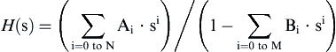
The roots of the numerator give the zero locations of the Laplace transform, and the roots of the denominator give the pole locations of the s-transform. These zeros and poles will characterize the filter frequency response.
Similar to digital filters, analog filters can also be defined by their impulse response. In the digital domain, an impulse is defined as a single sample with value = 1. For the analog world, this is not as simple. The answer is to define a function called the delta dirac, known as δ(t). It is a strange function. It has infinite height and zero width, but the area under its integral is equal to 1. It is essentially a spike located at zero along the number line. This is the continuous signal equivalent to a digital impulse. We can define the impulse response of an analog filter as follows.
So the output is the impulse response when the input is δ(t).
Now recall that s is a complex number. We can evaluate the Laplace transform, and determine where it's zeros (values of where transform numerator goes to zero) and where it's poles (values of s where the transform denominator goes to zero), and plot these locations on the complex number plane. In this context, the complex number plane is known as the s-plane (Fig. C.1).
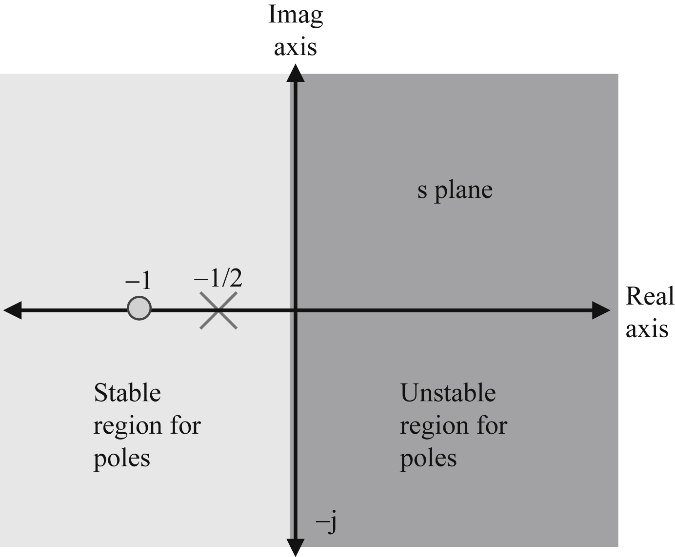
Next, we will go through a simple example to clarify
We can see that there is a single zero at s = −1, and a single pole at s = −1/2. The frequency response is evaluated by setting s = jω, and evaluating for −∞ < ω < ∞.
The filter's response is determined by the pole and zero locations. Use of the Laplace transform facilitates the design of analog filters.
We have mentioned that filters with feedback can be unstable. We can examine a simple case to see when this is true.
which has a single pole at s = 1/B1.
To determine stability, we compute the impulse response of the filter. Because of the simplicity of this example, the response of filter with x(t) = δ(t) can be computed directly from the differential equation. We will find that:
If B1 is negative, the exponential will decay over time—this is considered a stable response. But if B1 is positive, the impulse response will grow to infinity over time—this is an unstable response. This leads to the following general rule with analog filters.
All poles must be on left side of s-plane.
There is no restriction on location of zeros.
..................Content has been hidden....................
You can't read the all page of ebook, please click here login for view all page.