
Chapter 1
Numerical Representation
Abstract
This chapter deals with the issues of numerical representation of data in a digital signal processing. As all digital devices operate using bits, numerical values must be converted into a value representable using bits. Fixed point representation is most common, where numerical values are mapped into a field of bits covering a range of integer values, or alternately, a set of fractional values from −1 to 1. A more complex alternative is floating point that is similar to scientific notation. In this case, a numerical value is represented using a mantissa and exponent, along with a sign bit. This has the advantage of being able to cover a much wider range of numbers, both very large and very small.
Keywords
Exponent; Fixed point number; Floating point number; LSB; Mantissa; MSB
To process a signal digitally, it must be represented in a digital format. This may seem obvious, but it turns out that there are a number of different ways to represent numbers, and this representation can greatly affect both the result and the amount of circuit resources required to perform a given operation. This particular chapter is focused more for people who are implementing DSP and is not really required to understand fundamental DSP concepts.
Digital electronics operate on bits of course, which are used to form binary words. The bits can be represented as binary, decimal, octal or hexadecimal, or other form. These binary numbers can be used to represent “real” numbers. There are two basic types of arithmetic used in DSP, floating point or fixed point. Fixed point numbers that have a fixed decimal point as part of the number. Examples are 1234 (same as 1234.0), or 12.34 or 0.1234. This is type of number we normally use everyday. Floating point is a number with an exponent. The most common example would be scientific notation, used on many calculators. In floating point, 1,200,000 would be expressed as 1.2 × 10⁶, and 0.0000234 would be expressed as 2.34 × 10⁻⁵. Most our discussion will focus on fixed point numbers, as this is most commonly found in DSP applications. Once we understand DSP arithmetic issues with fixed point numbers, then there is short discussion on floating point numbers.
In DSP, we will pretty much exclusively use signed numbers, meaning that there are both positive and negative numbers. This leads into the next point, which is how to represent the negative numbers.
In signed fixed point arithmetic, the binary number representations will include a sign, a radix, or decimal point, and the magnitude. The sign indicates whether the number is positive or negative, and the radix (also called decimal) point separates the integer and fractional parts of the number.
The sign is normally determined by the left most, or most significant bit (MSB). The convention zero is used for positive, and one for negative. There are several formats to represent negative numbers, but the almost universal method is known as “2s complement”. This is the method discussed here.
Furthermore, fixed point numbers are usually represented as either integer or fractional. In integer representation, the decimal point is to the right of the least significant bit (LSB), and there is no fractional part in the number. For an 8-bit number, the range which can be represented is from −128 to +127, with increments of 1.
In fractional representation, the decimal point is often just to the right of the MSB, which is also the sign bit. For an 8-bit number, the range that can be represented is from −1 to +127/128 (almost +1), with increments of 1/128. This may seem a bit strange, but in practice, fractional representation has advantages, as will be explained.
This chapter will present several tables, with each row giving equivalent binary and hexadecimal numbers. The far right column will give the actual value in the chosen representation; for example, 16-bit integer representation. The actual value represented by the hex/binary numbers will depend on which representation format is chosen.
1.1. Integer Fixed Point Representation
Below are some examples showing the 2s complement integer fixed point representation (see Table 1.1).
The 2s complement representation of the negative numbers may seem nonintuitive, but it has several very nice features. There is only one representation of 0 (all 0s), unlike other formats which have a “positive” and “negative” zero. Also, addition and multiplication of positive and negative 2s complement numbers work properly with traditional digital adder and multiplier structures. A 2s complement number range can be extended to the left by simply replicating the MSB (sign bit) as needed, without changing the value.
The way to interpret a 2s complement number is using the following mapping for each bit. A 0 bit in a given location of the binary word means no weight for that bit. A 1 in a given location means to use the weight indicated. Notice the weights double with each bit moving left, and the MSB is the only bit with a negative weight. You should satisfy yourself that all negative numbers will have an MSB of 1, and all positive numbers and zero have an MSB of 0 (see Table 1.2).
Table 1.1
8-Bit Signed Integer Representation
| 8-Bit Integer Representation | ||
| Binary | Hexadecimal | Actual Decimal Value |
| 0111 1111 | 0x7F | 127 |
| 0111 1110 | 0x7E | 126 |
| 0000 0010 | 0x02 | 2 |
| 0000 0001 | 0x01 | 1 |
| 0000 0000 | 0x00 | 0 |
| 1111 1111 | 0xFF | −1 |
| 1111 1110 | 0xFE | −2 |
| 1000 0001 | 0x81 | −127 |
| 1000 0000 | 0x80 | −128 |


This can be extended to numbers with larger number of bits. Below is an example with 16 bits. Notice how the numbers represented in a lesser number of bits (say 8 bit for example) can be easily put into 16-bit representation by simply replicating the MSB of the 8-bit number by eight times and tacking onto the left to form a 16-bit number. Similarly, as long as the number represented in the 16-bit representation is small enough to be represented in 8 bits, the left most bits can simply be shaved off to move to the 8-bit representation. In both cases, the decimal point stays to the right of the LSB and does not change location. This can be easily seen by comparing, for example, the representation of −2 in the 8-bit representation table above and again in the 16-bit representation table below (Table 1.3).
Table 1.3
2s Complement 16-Bit Signed Integer Representation and Weighting
| 16-Bit Signed Integer Representation | ||
| Binary | Hexadecimal | Actual Decimal Value |
| 0111 1111 1111 1111 | 0x7FFF | 32,767 |
| 0111 1111 1111 1110 | 0x7FFE | 32,766 |
| 0000 0000 1000 0000 | 0x0080 | 128 |
| 0000 0000 0111 1111 | 0x007F | 127 |
| 0000 0000 0111 1110 | 0x007E | 126 |
| 0000 0000 0000 0010 | 0x0002 | 2 |
| 0000 0000 0000 0001 | 0x0001 | 1 |
| 0000 0000 0000 0000 | 0x0000 | 0 |
| 1111 1111 1111 1111 | 0xFFFF | −1 |
| 1111 1111 1111 1110 | 0xFFFE | −2 |
| 1111 1111 1000 0001 | 0xFF81 | −127 |
| 1111 1111 1000 0000 | 0xFF80 | −128 |
| 1111 1111 0111 1111 | 0xFF80 | −129 |
| 1000 0000 0000 0001 | 0xFF80 | −32,767 |
| 1000 0000 0000 0000 | 0xFF80 | −32,768 |

| MSB | LSB | ||||||||||||||
| −32,768 | 16,384 | 8192 | 4096 | 2048 | 1024 | 512 | 256 | 128 | 64 | 32 | 16 | 8 | 4 | 2 | 1 |
| −215 | 214 | 213 | 212 | 211 | 210 | 29 | 28 | 27 | 26 | 25 | 24 | 23 | 22 | 21 | 20 |

Now, let us look at some examples of trying to adding combinations of positive and negative 8-bit numbers together, using a traditional unsigned digital adder. We throw away the carry bit from the last (MSB) adder stage.
| Case #1: Positive and negative number sum | ||
| +15 | 0000 1111 | 0x0F |
| −1 | 1111 1111 | 0xFF |
| = 14 | 0000 1110 | 0x0E |
| Case #2: Positive and negative number sum | ||
| −31 | 1110 0001 | 0xE1 |
| +16 | 0001 0000 | 0x80 |
| = −15 | 1111 0000 | 0xF0 |
| Case #3: Two negative numbers being summed | ||
| −31 | 1110 0001 | 0xE1 |
| −64 | 1100 0000 | 0xC0 |
| = −95 | 1010 0001 | 0xF0 |
| Case #4: Two positive numbers being summed, result exceeds range | ||
| +64 | 0100 0000 | 0x40 |
| +64 | 0100 0000 | 0x40 |
| = 128 | 1000 0000a | 0x80a |

Integer representation is often used in many software applications, because it is familiar and works well. However, in DSP, integer representation has a major drawback. That is because in DSP, there is a lot of multiplication. When you multiply a bunch of integers together, the results start to grow rapidly. It quickly gets out of hand and exceeds the range of values that can be represented. As we saw above, 2s complement arithmetic works well, as long as you do not exceed the numerical range. This has led to the use of fractional fixed point representation.
1.2. Fractional Fixed Point Representation
The basic idea is all values are in the range from +1 to −1, so if they are multiplied, the result will not exceed this range. Notice that to convert from integer to 8-bit signed fractional, the actual values are all divided by 128. This maps the integer range of +127 to −128 to almost +1 to −1 (Tables 1.4 and 1.5).
Table 1.4
8-Bit Signed Fractional Representation and Bit Weighting
| 8-bit Fractional Representation | ||
| Binary | Hexadecimal | Actual Decimal Value |
| 0111 1111 | 0x7F | 127/128 = 0.99219 |
| 0111 1110 | 0x7E | 126/128 = 0.98438 |
| 0000 0010 | 0x02 | 2/128 = 0.01563 |
| 0000 0001 | 0x01 | 1/128 = 0.00781 |
| 0000 0000 | 0x00 | 0 |
| 1111 1111 | 0xFF | −1/128 = −0.00781 |
| 1111 1110 | 0xFE | −2/128 = −0.01563 |
| 1000 0001 | 0x81 | −127/128 = −0.99219 |
| 1000 0000 | 0x80 | −1.00 |

| 8-Bit Signed Fractional | MSB | LSB | ||||||
| Weight | −1 | 1/2 | 1/4 | 1/8 | 1/16 | 1/32 | 1/64 | 1/128 |
| Weight in powers of 2 | −20 | 2–1 | 2–2 | 2–3 | 2–4 | 2–5 | 2–6 | 2–7 |

Fractional fixed point is often expressed in Q format. The representation shown above is Q15, which means that there are 15 bits to the right of the radix or decimal point. It might also be called Q1.15, meaning that there is 15 bits to right of decimal point, and 1 bit to left.
The key property of fractional representation is that the numbers grow smaller, rather than larger, during multiplication. And in DSP, we commonly sum the results of many multiplication operations. In integer math, the results of multiplication can grow large quickly (see example below). And when we sum many such results, the final sum can be very large, easily exceeding the ability to represent the number in a fixed point integer format.
As an analogy, think about trying to display an analog signal on an oscilloscope. You need to select a voltage range (volts/division) in which the signal amplitude does not exceed the upper and lower range of the display. At the same time, you want the signal to occupy a reasonable part of the screen, so the detail of the signal visible. If the signal amplitude only occupies 1/10 of a division, for example, it is difficult to see the signal.
To illustrate this, imagine using 16-bit fixed point, and the signal has a value of 0.75 decimal or 24,676 in integer (which is 75% of full scale) and is multiplied by a coefficient of value 0.50 decimal or 16,384 integer (which is 50% of full scale).
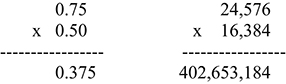
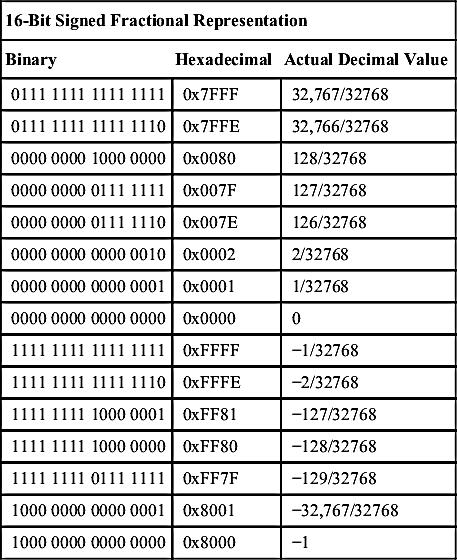
Table 1.5
16-Bit Signed Fractional Representation and Bit Weighting
| 16-Bit Signed Fractional Representation | ||
| Binary | Hexadecimal | Actual Decimal Value |
| 0111 1111 1111 1111 | 0x7FFF | 32,767/32768 |
| 0111 1111 1111 1110 | 0x7FFE | 32,766/32768 |
| 0000 0000 1000 0000 | 0x0080 | 128/32768 |
| 0000 0000 0111 1111 | 0x007F | 127/32768 |
| 0000 0000 0111 1110 | 0x007E | 126/32768 |
| 0000 0000 0000 0010 | 0x0002 | 2/32768 |
| 0000 0000 0000 0001 | 0x0001 | 1/32768 |
| 0000 0000 0000 0000 | 0x0000 | 0 |
| 1111 1111 1111 1111 | 0xFFFF | −1/32768 |
| 1111 1111 1111 1110 | 0xFFFE | −2/32768 |
| 1111 1111 1000 0001 | 0xFF81 | −127/32768 |
| 1111 1111 1000 0000 | 0xFF80 | −128/32768 |
| 1111 1111 0111 1111 | 0xFF7F | −129/32768 |
| 1000 0000 0000 0001 | 0x8001 | −32,767/32768 |
| 1000 0000 0000 0000 | 0x8000 | −1 |
| MSB | LSB | ||||||||||||||
| −1 | 1/2 | 1/4 | 1/8 | 1/16 | 1/32 | 1/64 | 1/128 | 1/256 | 1/512 | 1/1024 | 1/2048 | 1/4096 | 1/8192 | 1/16,384 | 1/32,768 |
| −20 | 2–1 | 2–2 | 2–3 | 2–4 | 2–5 | 2–6 | 2–7 | 2–8 | 2–9 | 2–10 | 2–11 | 2–12 | 2–13 | 2–14 | 2–15 |

Now the larger integer number can be shifted right after every such operation to scale the signal within a range it can be represented, but most DSP designers prefer to represent numbers as fractional, as its a lot easier to keep track of the decimal point.
Now consider multiplication again. If two 16-bit numbers are multiplied, the result is a 32-bit number. As it turns out, if the two numbers being multiplied are Q15, you might expect the result in the 32-bit register to be a Q31 number (MSB to left of decimal point, all other bits to right). Actually, the result is in Q30 format—the decimal point has shifted down to the right. Most DSP processors will automatically left shift the multiplier output to compensate for this, when operating in fractional arithmetic mode. In FPGAs (field programmable gate arrays) or ASIC (application specific integrated circuit) hardware design, the designer may have to take this into account when connecting data buses between different blocks. There is an appendix to explain the need for this extra left shift in detail, as it will be important for those implementing fractional arithmetic on FPGAs or DSPs.

After left shift by one
If we use only the top 16-bit word from multiplier output, after the left shift we get
1.3. Floating Point Representation
Many of these complications can be avoided by using floating point format. Floating point format is basically like scientific notation on your calculator. Because of this, a floating point number can have a much greater dynamic range than a fixed point number with equivalent number of bits. Dynamic range means the ability to represent very small numbers to very large numbers.
The floating point number has both a mantissa (which includes sign) and exponent. The mantissa would be the value in the main field of your calculator, and the exponent would be off to the side, usually as a superscript. Each of these is expressed as a fixed point number (meaning the decimal point is fixed). The mantissa represents the fractional portion, with a range from 0 to 0.999… There is also an implicit one in the mantissa, meaning it is not present in the mantissa. So the range of the fractional portion is actually from 1 to 1.999… The size of the mantissa and exponent in number of bits will vary depending on which floating point format is used (Table 1.6).
Table 1.6
Floating Point Numerical Formats
| Floating Point Formats | No of Mantissa Bits | No of Exponent Bits |
| Half Precision | 10, plus 1 bit to determine sign | 5, unsigned integer, biased by 25–1 = 31 |
| Single Precision | 23, plus 1 bit to determine sign | 8, unsigned integer, biased by 28–1 = 127 |
| Double Precision | 52, plus 1 bit to determine sign | 11, unsigned integer, biased by 211–1 = 2047 |
Common floating point formats require 16 bits, 32 bits, and 64 bits to represent.
Single and double precision are very common in computing, usually designated as “float” and “double,” respectively. Half precision has seen little use until recently, when it has become popular in machine learning.
The largest single precision number that can be represented is:
The smallest single precision number that can be represented without denormalization:
This is a far great dynamic range that can be expressed using 32-bit fixed point. There are some additional details in floating point to designate conditions such as +/− infinity, or “not a number” NaN, as may occur with a division by zero.
The drawback of floating point calculations is the resources required. When adding or subtracting two floating point numbers, the number with smaller absolute value must be first adjusted so that its exponent is equal to the number with larger absolute value, then the two mantissas can be added. If the mantissa result requires a left or right shift to represent, the exponent is adjusted to account for this shift. When multiplying two floating point numbers, the mantissas are multiplied, and the exponents are summed. Again, if mantissa result requires a left or right shift to represent, the new exponent must be adjusted to account for this shift. All of this requires considerably more circuitry than fixed point computations and have higher power consumption as well. For this reason, many DSP algorithms use fixed point arithmetic, despite the ones on the designer to keep track of where the decimal point is and ensure that the dynamic range of the signal never exceed the fixed point representation, or else become so small that quantization error become significant. We will see more on quantization error in a later chapter.
For those interested in more information on floating point arithmetic, there are many texts that go into this in detail, or else one can google IEEE754 floating point.
..................Content has been hidden....................
You can't read the all page of ebook, please click here login for view all page.