
The Anatomy of Lift Enhancement
Outline
10.1.1 The Content of this Chapter
10.2 Leading-Edge High-lift Devices
10.2.1 Hinged Leading Edge (Droop Nose)
10.2.2 Variable-camber Leading Edge
Folding, Bull-nose Krüger Flap
The Airload-actuated Slat (or the Automated Handley-Page Slat)
10.2.6 Summary of Leading Edge Device Data
10.3 Trailing Edge High-lift Devices
10.3.3 Junkers Flap or External Flap
10.3.4 The single-slotted Flap
Fixed-vane Double-slotted Flap
Articulating-vane Double-slotted Flap
10.3.8 Summary of Trailing Edge Device Data
10.4 Effect of Deploying High-lift Devices on Wings
10.4.1 Lift Distribution on Wings with Flaps Deflected
Estimation of the Maximum Lift Coefficient
Estimation of the Pitching Moment Coefficient
Aerodynamic Effectiveness of Wingtips
The Downturned Booster Wingtip
10.5.9 The Polyhedral Wing(tip)
10.1 Introduction
It was discovered early on in aviation that in order to achieve high airspeeds, wings of small areas were needed. This is clearly evident from the drag equation, D = ½ρV2·S·CD, which shows that the wing area affects the drag proportionally – halve the area, halve the drag. However, a large wing area is desirable for low-speed operations, take-off and landing, and this is apparent from the lift equation, L = ½ρV2·S·CL. The solution to the conflicting problem of high lift and low drag has been to keep S as low as possible, and then try to increase lift capability by increasing CLmax. This is most effectively accomplished using special mechanical devices on the wing that enhance its lifting capability; these were the high-lift devices. They allowed the transformation of the wing from a shape useful for low-speed flight into one conducive to high airspeeds and back again.
In short, the purpose of lift enhancement is to (1) allow the airplane to operate at lower airspeeds, which translates into shorter runway requirements; (2) provide improved L/D in the T-O configuration to help complying with noise requirements during departure climb; (3) increase drag during landing, so that the approach glide angle can be made steeper, making the aircraft easier to land; (4) increase drag during landing in order to reduce floating in ground effect, and (5) reduce AOA near maximum lift so the airplane is easier to land at low airspeeds.
A great example of the use of high-lift devices is shown in one of the most interesting passenger jetliners ever produced, the Boeing B-727 tri-jet (see Figure 10-1). It was developed in the 1960s to allow operation from much shorter runways than the jetliners of the day, which all required long runways for operation. This was achieved using an impressive assortment of leading and trailing edge high-lift devices, giving it one of the highest CLmax of any aircraft. This chapter will present leading edge devices first, followed by trailing edge devices. Finally, methods to account for the addition of such devices to the airplane as a whole will be presented.

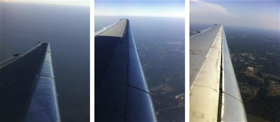
FIGURE 10-1 A Boeing B-727 passenger airliner taxiing into T-O position. Visible are parts of its sophisticated wing high-lift system; the folding, bull-nose Krüger Flap can be seen on the inboard part of the wing, and the three-position slats on the outboard part of the wing. (Photo by Phil Rademacher)
The capability of high-lift devices will be the focus of this chapter. These devices usually serve two purposes: to change the camber of the wing’s airfoils, and delay flow separation. As such, there are two kinds of high-lift devices: passive and active. Passive high-lift devices do not require additional energy to provide lift enhancement, whereas active ones do. Examples of active lift enhancement devices include the jet-blown flap and vectored thrust. Since they add substantial cost to the aircraft, in terms of both hardware and operation, they are never used on GA aircraft, but rather in specialized military aircraft. For this reason, only the former kind will be dealt with here.
There are also two kinds of passive high-lift devices: those that are mounted to the leading edge and those mounted to the trailing edge. As the reader will see shortly, a large number of such devices have been invented – in both groups. As usual, all have their pros and cons, but as a rule of thumb, the more complicated such a system is the more lift it supplies, but it also adds more weight, cost, and operational penalties.
10.1.1 The Content of this Chapter
• Section 10.2 presents helpful design information for the selection of leading edge high-lift systems.
• Section 10.3 presents helpful design information for the selection of trailing edge high-lift systems or flaps.
• Section 10.4 presents methods to estimate the impact of adding partial span high-lift devices.
• Section 10.5 introduces a number of different wingtip options and discusses their advantages and disadvantages.
10.2 Leading-Edge High-lift Devices
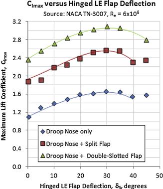
Generally, the purpose of the leading edge high-lift device is to increase the stall angle and maximum lift coefficient of the airfoil without a significant shift in the lift curve, as happens with trailing edge devices. Thus, deploying a leading edge device will have much less effect on trim than do flaps. The effect is described in Section 8.3.9, The effect of addition of a slot or slats, in addition to the text here. A summary of the aerodynamic properties of many of the leading edge devices discussed are given in Table 10-1. This data is helpful during the conceptual and preliminary design phases. The aerodynamic data contains information on change in maximum lift coefficient, lift coefficient at zero AOA, minimum drag, and pitching moment.
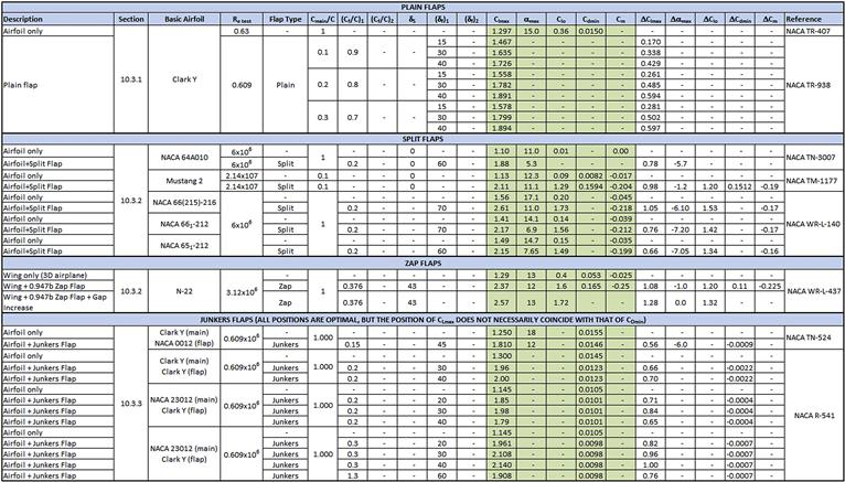
TABLE 10-1
Summary of the Aerodynamic Properties of Leading Edge Devices
Abbreviations:
LE = leading edge
TE = trailing edge
Re test = Reynolds number during test
CS = chord of LE device
C = airfoil chord
Dbl = double
δS = deflection angle of LE device
(δf)1 = deflection of element 1 of a TE device
(δf)1 = deflection of element 2 of a TE device
Clmax = max section lift coefficient
αmax = stall AOA
Clo = lift coefficient at α = 0°
Cdmin = minimum section drag coefficient
Cmo = pitching moment coefficient at α = 0°
It is important for the designer to keep in mind that, in general, leading edge devices increase the stall AOA so much that alone they are surprisingly impractical. For instance, a fixed slot will increase the stall AOA by some 9°. This means that an airplane normally stalling at an AOA of about 15° would stall around 24° with them deployed. This means that in order to realize the benefits of the higher CLmax, the airplane would have a deck angle that would be very impractical for the operation of the airplane. The remedy is to mix them with trailing edge flaps. These always reduce the stall AOA. Thus, the 9° of stall AOA added by the leading edge device is reduced to perhaps an overall 2° increase.
As stated earlier, the maximum lift capability of an airfoil can be improved by two means: by increasing curvature and delaying flow separation. It is also possible to improve stall by increasing the leading edge radius, although this is arguably an airfoil design topic. This section presents a description of a number of such devices, some of which only increase curvature while others do both. Some of those devices are extremely simple and are ideal for simple and slow-flying aircraft, for instance bushplanes. Others are far more complex and require sophisticated four-bar linkages to deliver them into a proper position and shape. They are intended for commercial jetliners and business jets. Movable mechanical leading edge devices are subjected to many challenges. They are fundamental to the operational safety of the airplane, so they have to be reliable – while reacting substantial loads. Jamming is not an option.
The effectiveness of the leading edge devices is best described by the resulting change in Clmax and αstall. This is a direct measure of their ability to postpone flow separation. This is a very important capability, because while it is possible to greatly increase the airfoil curvature geometrically, lift will not increase unless the flow can be made to follow that curvature. The effectiveness is thus highly dependent on the geometry of the airfoil and the leading edge device. There are other characteristics of importance too – impact on drag and pitching moment. These characteristics will be presented based on the availability of experimental data in this section.
10.2.1 Hinged Leading Edge (Droop Nose)
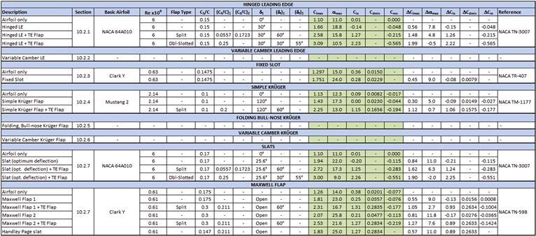
The hinged leading edge or droop nose or leading edge flap is a mechanical device that increases the leading edge camber and therefore CLmax and αstall of the wing (see Figure 10-2). The device reduces the stalling speed and can also reduce roll instability at stall. Mechanically it is a very simple device and has limited impact on drag when retracted when compared to other such devices, as it seals the slot, preventing air from “leaking” from the lower to the upper surface. However, the increase in CLmax is limited due to the small-radius curvature on the upper surface, which may induce flow separation. This is caused by the absence of a slot and discontinuity in the curvature on the upper surface, which may spur a separation bubble. A typical deflection range is 15–40°. The main strengths of the device are its low cost, relative ease of manufacturing, and low impact on weight and drag. An aircraft that uses the droop nose leading edge is the Lockheed F-104 Starfighter; the increase in maximum lift is far too small to make it practical for use in passenger aircraft.
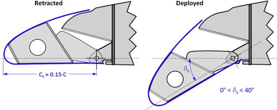
Figure 10-3 shows flow visualization made of the hinged leading edge (and plain flap) and reveals several issues that are detrimental to the effectiveness of the device. The designer should be aware of such issues, as this will aid in the selection and justification for alternative leading edge devices. In all three pictures, the leading and trailing edge flaps, denoted by δs and δf, respectively, are deflected 33°. The top, center, and bottom pictures show the airfoil at a α of 4°, 13°, and 25°, respectively.
The top picture reveals that the stagnation point is located just above the nose radius of the leading edge and this requires the fluid to flow downward around the nose. However, the boundary layer lacks the energy to fully flow around the nose radius and instead separates from the surface and creates a separation bubble on the lower surface. This results in a diminished circulation around the airfoil and would cause additional and, possibly, unexpected drag and reduction in lift of the configuration. Of course, the solution is reduced angle of deflection of the nose droop at that AOA – but at least the picture shows the consequence of too much deflection. Also note the flow separation behind the flap. The flow in this experiment is at a low Reynolds number, but at a flap deflection of 33° even large airplanes featuring a plain flap (see Section 10.3.1, Plain flap) also suffer such massive separation. The effect of flow separation behind flaps is discussed in more detail in Section 10.3, Trailing edge high-lift devices.
The center picture in Figure 10-3 shows the airfoil at a higher AOA of 13°. The stagnation point has moved closer to the tip of the nose, causing the elimination of the separation bubble seen in the top picture, behind and below the drooped nose. However, another one has begun to form on the upper surface, right behind the discontinuity in the upper curve. This indicates the sensitivity of such surfaces to discontinuity in surfaces, and this is the primary drawback of the device. The bottom picture shows the airfoil deep in the post-stall region, at an AOA of 25°. The stagnation point is now below the nose tip and the separation bubble on the trailing edge of the drooped nose has increased substantially. It has, effectively, become a part of the massive separation region behind the stalled airfoil.
General Design Guidelines
NACA TN-3007 [1] provides helpful guidelines for the initial design of a fixed slot. Using a symmetrical NACA 64A010 airfoil, the results of an investigation of combinations of a leading edge slat and flap, and split flap and a double-slotted flap are presented. With respect to the leading edge flap, the investigation showed that for Re ≈ 2 × 10⁶ a droop deflection δs = 40° resulted in the highest Clmax. For higher Re, δs = 30° was found to result in the highest Clmax. The reference did not investigate drag.
Aerodynamic Properties
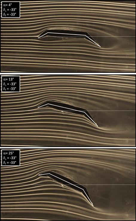
Results for the hinged leading edge using a NACA 64A010 airfoil are given in Table 10-1 and are obtained from Ref. [1], for a Reynolds number of 6 × 10⁶. Results for other airfoils and conditions are likely to be different. A maximum change in maximum section lift coefficient to be expected is ΔClmax ≈ 0.56. This will increase the stall AOA by about Δαmax ≈ 7.8°, and the change in pitching moment coefficient is approximately ΔCm ≈ -0.048.
As intuition would hold, the maximum lift coefficient increases with the deflection of the hinged leading edge, up to a maximum around 30°. The variation of Clmax is plotted against the deflection in Figure 10-4. Higher deflections reduce this maximum and can be attributed to separation of effects caused by the sharp curvature around the hingeline.
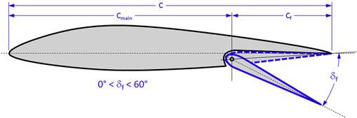
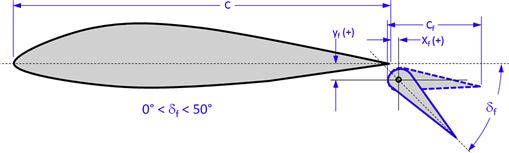
10.2.2 Variable-camber Leading Edge
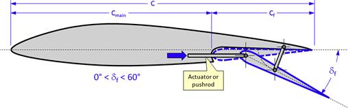
The variable-camber leading edge is a device designed to increase the airfoil camber at the leading edge (see Figure 10-5) while minimizing impact on cruise drag. Like its droop nose sibling, the device increases the low-pressure peak at higher AOAs and therefore CLmax. However, it offers improved continuity in the upper surface curvature, making it smoother than the hinged leading edge, discussed above. This reduces the possibility of the formation of a separation bubble on the top surface. The skin extending from the main element of the wing onto the leading edge prevents leakage drag, rendering the device more efficient (less drag). When used with an active flight control system the device can be controlled to offer mission adaptability. This makes it primarily suitable for aircraft that must maneuver at higher airspeeds, such as fighter aircraft.
The device uses a complicated mechanical linkage (not shown in schematic) to ensure the compound motion necessary to ensure a smooth flexible skin curvature. This mechanism adds weight and complexity to the structure and increases design and development costs, not to mention maintenance. Additionally, the device calls for the use of flexible skin and movable linkages in the mechanical system, yielding a leading edge that no longer contributes to the wing stiffness and flutter resistance. The device does not yield a large increase in CLmax, so it is not used for jetliners.
A typical deflection range is 15–30°. The main strength of the device is a smooth upper surface and, thus, reduced impact on drag at cruise. Among its drawbacks are high cost, complex manufacturing of mechanical operation, a moderate impact on weight, and reduced maximum lift due to the absence of slot flow. The F-111 AFTI (Advanced Fighter Technology Integration) [2] Mission Adaptive Wing test program is really the only example of this concept. Boeing also performed studies on a mission adaptive wing for a commercial jetliner [3]. The study assumed both the leading and trailing edge devices featured a smooth variable-camber mechanism and it was shown such a design would permit less sweep and improved aerodynamic efficiency below the design Mach number.
Aerodynamic Properties
Not available at this time. In the absence of better data, aerodynamic properties are expected to be similar to those of the droop nose leading edge flap, which are presented in Table 10-1.
10.2.3 Fixed Slot
The fixed slot is a wing design (or airfoil selection) philosophy and not a mechanical device, per se, as it is immovable (see Figure 10-8). Its invention is usually attributed to Gustav Lachmann and Sir Handley Page (see Section 10.2.5, The leading edge slat). It has been used with great success in many short take-off and landing (STOL) aircraft, among which are the Fieseler Fi-156 Storch (see Figure 10-7); Zenith STOL series CH 701, CH 750, CH 801, and Heintz Zenith; and Westland Lysander. The device is ideal for very simple slow-flying aircraft whose primary capability is getting into and out of small patches of land most people would not dignify with the noun “airfield.” However, a more sophisticated variation of the fixed slot exists in high-speed aircraft too. The Douglas DC-8 commercial jetliner widely used in the 1970s–1990s features fixed slots near the engine pylons. These are closed during cruise, but before landing these are opened to improve low speed handling.
The slot works through what is called the slat-effect. Conventional wisdom has it that the slot provides an access for high-pressure air from the lower surface to flow to the upper surface. Additionally, its shape accelerates this flow and somehow energizes the airflow over the upper surface of the airfoil, yielding a higher Clmax and stall AOA. On the other hand, in a famous paper, A. M. O. Smith [4] disputes this explanation and points out that the airflow through the slot is actually reduced. In fact, the slat works more like a small wing placed in front of the larger wing rather than a device that accelerates slot flow.
As shown in a paper by Liebeck [5], Smith’s explanation can be realized by replacing the leading edge element with a vortex (see Figure 10-6). The circulation caused by this vortex induces velocity on the larger airfoil that reduces the airspeed over its leading edge and through the slot and this drops the pressure peak on the leading edge of the airfoil, delaying stall. This description is supported by both wind tunnel tests and analyses performed using computational fluid dynamics [4].
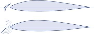
FIGURE 10-6 The workings of the slat explained using vortex flow. (based on Ref. [4])
This way, the slat-effect acts to reduce the pressure peak and this delays the flow separation and allows the airfoil to reach a higher AOA and, thus, generate higher Clmax than possible without it.
The fixed slot is very simple in construction compared to other leading edge devices. It is a very effective and inexpensive device that allows aircraft like the Fieseler Storch (see Figure 10-7) to achieve a CLmax in excess of 4.2.1

FIGURE 10-7 A German Fieseler Fi-156 Storch STOL aircraft boasting its fixed slot. (Photo by Nick Candrella)
As stated above, the fixed slot is ideal for aircraft intended for STOL operation, as long as aerodynamic efficiency is not an issue. The slot prevents laminar flow beyond its trailing edge so, even at low AOAs, it greatly increases the drag of the airfoil when compared to the “clean” airfoil, rendering it impractical for high-speed aircraft. A fixed slot is used on the horizontal stabilator of the Cessna 177 Cardinal to prevent it from stalling when flaps are deployed and CG is in a forward position, something requiring a large stabilator deflection.
General Design Guidelines
NACA TR-407 [6] provides helpful guidelines for the initial design of a fixed slot. Spurred by the popularity of the Handley-Page slat, which would increase drag by a factor of more than 3 when deployed, the report details the investigation of a series of fixed slots in an attempt to reduce the minimum drag coefficient without detrimentally affecting the maximum lift coefficient and the stall AOA of a Clark Y airfoil. Of the configurations tested, the one shown in Figure 10-8 was found to yield the best results. It was found that reducing the drag coefficient of the auxiliary airfoil does not necessarily reduce the drag of the combination and may even cause it to increase and the maximum lift to decrease. Rounding the nose of the main airfoil was determined to be the most promising way to reduce the drag of the combination. It was also shown that moving the depth of the slot aft (to the right in Figure 10-8) did not have appreciable effect on the aerodynamic characteristics of the combination.
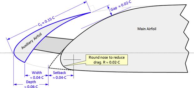
FIGURE 10-8 A schematic of a fixed slot. Airfoil (Clark Y) and dimensions are based on the optimum configuration as determined by Ref. [6].
Aerodynamic Properties
Results for the fixed slot using a Clark Y airfoil are given in Figure 10-9 and Table 10-1 and are obtained from Ref. [6]. The test Reynolds number was about 0.63 × 10⁶. A maximum change in maximum section lift coefficient to be expected is ΔClmax ≈ 0.45, about 0.11 less than that of the hinged leading edge. This will increase the stall AOA by about Δαmax ≈ 9°, the zero AOA lift coefficient will drop by about ΔClo ≈ −0.074, and the minimum drag coefficient will increase by about ΔCdmin ≈ 0.0079 (79 drag counts). Ultimately, the gain depends on the shape and the experimental setup does not represent an optimized geometry.
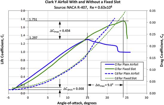
FIGURE 10-9 Effect of the fixed slot on the lift and drag characteristics of the Clark Y airfoil. Reproduced from Ref. [6].
10.2.4 The Krüger Flap
The Krüger flap was invented in 1943 by the German Werner Krüger (1910–), an aerodynamicist for Dornier, where he worked with the noted aerodynamicist Hermann Schlichting (1907–1982) [7, p. 200]. Krüger’s career goal was to improve flight characteristics by boundary-layer control. He patented his invention in 1944 and it was first used in the Boeing 367-80, the prototype of the venerable Boeing 707. The flap is a two-position device (retracted-deployed) and, as such, at first glance is mechanically a simple device. The deployed position is generally biased toward landing (CLmax) and not T-O [8]. Optimizing it to other flight conditions would require other deployment angles and this would call for a more complex mechanism or improved geometry (e.g. bull-nose Krüger). Krüger flaps are ideal for the inboard wing as they delay flow separation to a lesser angle than the outboard slats and, therefore, improve roll stability. Of course the same effect can be achieved by other means too, rendering them largely obsolete.
Simple Krüger Flap
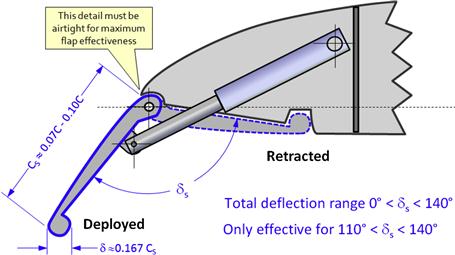
The simple Krüger flap is a high-lift device intended to increase the curvature of the camber of the airfoil to which it is mounted. It is used in some commercial jetliners to improve the high-lift capability of the under-cambered airfoil near the root of the fuselage2 and delay flow separation. As such, it is primarily used on the inboard part of the wing. The outside mold line (OML) of the device is essentially shaped like the lower surface of the leading edge of the airfoil. Its geometry is highly dependent on the geometry of the leading edge and this inflicts an aerodynamic limitation on its shape. The effectiveness of the simple Krüger flap with variations in AOA is generally considered poor. It is not used on any modern airplane. The flap rotates into a position that is approximately 110° to 140° with respect to the chord line (see Figure 10-10). Examples of aircraft that use the simple Krüger flap are (as previously mentioned) the Boeing 707, Convair 880, and Convair 990, which featured it from root to tip.
Design Guidelines
The function of the Krüger flap is explained by noting that at the proper deflection angle the stagnation point of the incoming airflow is positioned near the leading edge of the flap. This reduces the excessive airspeed over the leading edge of the airfoil by allowing the airflow to accelerate over a longer distance. The reduction in local airspeeds, in turn, means the associated pressure peaks are reduced and this delays the formation of flow separation (see schematic in Figure 10-11). Consequently, the airfoil stalls at a higher AOA [7, pp. 170–171]. In short, the general design requires a trial and error approach through extensive wind tunnel testing, although some basic design guidelines can be presented.
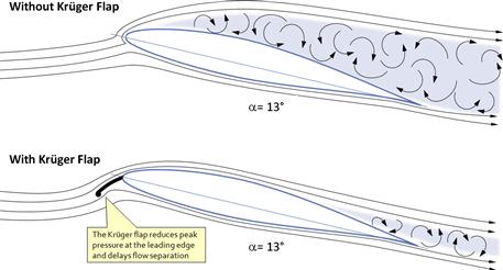
FIGURE 10-11 The simple Krüger flap in action. The upper figure shows an airfoil stalled at the given α. By repositioning the stagnation point, air is now allowed to accelerate over greater distance, but this reduces the pressure peaks, delaying the flow separation and pushing the stall to a higher α. (based on Ref. [7])
Krüger investigated the device in NACA TM-1177 [9], with and without the presence of a split flap. He found that the chord length of the flap, CS, should be 0.07C to 0.10C, where C is the airfoil chord length. He tested two chord lengths, one which was 0.05C and the other 0.10C, and found the shorter one actually reduced the maximum lift. From this he concluded that a minimum chord length should be 0.07C, as shown in Figure 10-10. He suggested the leading edge of the flap should feature a ball at the leading edge with a radius around 0.167 CS, although increasing it to 0.334 CS showed no detriment. However, allowing air to flow through a gap between the flap and the leading edge of the wing reduced the increase in ΔClmax, cited below, by about 50%–70%.
Aerodynamic Properties
Results for a 0.01·C Krüger flap using a Mustang 2 airfoil are given in Table 10-1. The test Reynolds number was about 2.14 × 10⁶. Per Ref. [9] the maximum increase in ΔClmax for the Krüger alone without trailing edge flaps amounted to ΔClmax ≈ 0.30, at a deflection angle δs = 130°. In fact, it must swing through approximately 90° before it even begins to increase the Clmax. This gain is negatively affected by the presence of a deflected trailing edge flap. The reference also tested a 0.2·C split flap at 60° deflection and found that with the flap ΔClmax increased only by 0.15, albeit for δs ranging from 100° to 120°. It is also stated that there was a substantial reduction in the magnitude of the low pressure region on the leading edge.
The Krüger flap will increase the stall AOA by about Δαmax ≈ 5°, zero AOA lift coefficient will drop by about ΔClo ≈ −0.093, and the minimum drag coefficient will increase by about ΔCdmin ≈ 0.0149 (149 drag counts), so it add substantial drag to the airplane. Change in pitching moment coefficient is approximately ΔCm ≈ −0.027. The combination of the Krüger flap and the 0.2·C split flap increased the stall AOA by some Δαmax ≈ 0.7°. While this may not seem like much, the reader is reminded that the primary purpose of the high-lift devices is to increase the lift without changing the stall AOA excessively (i.e. making it too large or too small).
Folding, Bull-nose Krüger Flap
The folding, bull-nose Krüger flap is an improvement over the simple Krüger flap, as it increases the curvature of the airfoil camber. The round bull-nose (see Figure 10-12) improves the effectiveness of the flap over a larger range of AOA by providing a larger area in which to “capture” the stagnation point. Just like the simple Krüger flap, the flap is a two-position device (retracted-deployed) whose deployed position is generally biased toward landing (CLmax) and not T-O. The folding, bull-nose Krüger flap is clearly more complicated than the simple one and often requires a slaved mechanical linkage that folds the bull-nose into the deployed and retracted positions. The flap is used on the Boeing 727 (see Figure 10-1 and Figure 10-12), 737, and 747 (see Figure 10-14) jetliners.
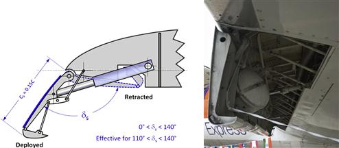
FIGURE 10-12 A schematic of the folding, bull-nose Krüger flap (based on Ref. [8]). The photo shows its implementation in a Boeing 727 commercial jetliner. (Photo by Nick Candrella)
As with the simple Krüger flap, the drawback is a limited increase in CLmax. As with the simple Krüger flap, the rigid flap is highly dependent on the lower surface of the leading edge and this may inflict an aerodynamic detriment to the geometry. However, it can be the ideal surface to control stall progression along the wing.
Aerodynamic Properties
In the absence of design data assume the properties discussed above for the simple Krüger flap. Results for the simple Krüger flap are given in Table 10-1.
Variable-camber Krüger Flap
The variable-camber Krüger flap is intended to improve the shape of the simple and bull-nose Krügers. It is capable of developing far superior curvature, greatly improving its aerodynamic properties when compared to the others. It is a two-position device (retracted-deployed). The deployed position is generally biased toward landing (CLmax) and not T-O. Each flap panel must be flexible and is thus usually made from fiberglass and in short sections (spanwise speaking). Two hat sections parallel to the leading edge are used to stiffen it in the spanwise direction and ensure chordwise flex only.
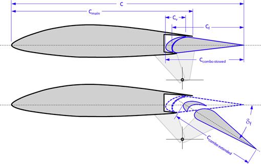
The flap deflects through approximately 120° angle from the stowed position (depending on leading edge geometry), during which it transforms from a more or less flat panel into a highly curved one. This feat requires a complex four-bar linkage to make certain it acquires the right shape and position (see schematic in Figure 10-13). This mechanism also explains why the device is so far only a two-position one. Adding a third position (say a T-O setting) that does not violate the quality of the other positions is destined to be challenging. The flexible panels act like bug shields and protect the leading edge from contamination. Figure 10-14 shows the combination of a bull-nose and variable-camber Krüger flaps on a Boeing 747-400 commercial jetliner.
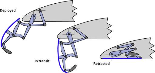
FIGURE 10-13 A schematic of the variable-camber Krüger flap. (based on Ref. [8])
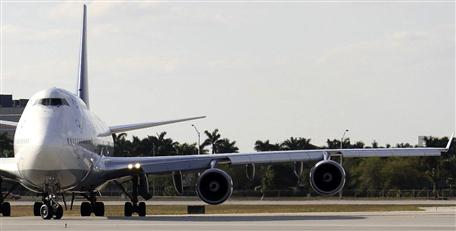
FIGURE 10-14 A Boeing 747-400 taxiing into take-off position, boasting a combination of bull-nose (inboard) and variable-camber Krüger flaps. (Photo by Phil Rademacher)
The sophistication of the actuation mechanism of the flap system is impressive – it is truly a marvel of engineering. However, in order to make the system work reliably, each part has to be made with tight tolerances. As a consequence, it is expensive to manufacture and maintain. The flap must be carefully rigged to prevent undesirable distortion of the panels under high air loads and be preloaded to avoid panel bulging (and the associated drag increase) when retracted.
In spite of the limitations, Krüger flaps should not be ignored as a potential candidate configuration for aircraft designed to sustain a laminar boundary layer over the wing’s upper surface. Since the flap is stowed on the lower surface of the airfoil, an opportunity exists for a smooth upper surface. To the author’s best knowledge, the Boeing 747 is the only aircraft currently in production to use the variable-camber Krüger flap. It was also featured on the proof-of-concept Boeing YC-14, a participant in the USAF Advanced Medium STOL Transport (AMST) project in the late 1970s.
Aerodynamic Properties
In the absence of design data assume the properties discussed above for the simple Krüger flap, although it is undoubtedly much better. Results for the simple Krüger flap are given in Table 10-1.
10.2.5 The Leading-Edge Slat
The idea of the slat dates back to 1918 to work by the German aeronautical engineer Gustav Lachmann (1896–1966). Lachmann’s original work has been translated into English in NACA TN-71 [10].
The slat was also developed independently by the British industrialist and aircraft manufacturer Sir Frederick Handley Page (1885–1962). In 1919, in order to avoid a patent conflict Page came to an agreement with Lachmann, who ended up working for Page until the end of his life [57]. The device was described publicly in a lecture given by Page before the British Royal Aeronautical Society in 1921 [4]. Handley Page seems to have been among the first to try it out in practice, put to use on a de Havilland D.H. 9. The device later became known as the Handley Page slot. Initially, it was fixed (as discussed in Section 10.2.3, Fixed slot), but later, the drag associated with it encouraged Handley-Page's chief engineer George Volkert and his assistant S. G. Ebel to develop a slot that was closed at low AOAs and automatically opened with increasing AOA, when the airplane slowed down [57] – the leading edge slat3 was born.
The two-position slat is a device that increases Clmax through the slat-effect, explained in Section 10.2.3, Fixed slot. Mechanically, it is moderately complex (Figure 10-15).

FIGURE 10-15 A schematic of the mechanical aspect of the two-position slat. (based on Ref. [8])
Important aerodynamic properties of slats are described in terms of the dimensions shown in Figure 10-16, but the motion is described in terms of:
(1) Extension forward of the leading edge (Δx or a).
(2) Downward drop below the leading edge (Δy or b).
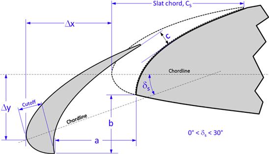
FIGURE 10-16 Definition of the geometric parameters pertaining to the deployment of the two-position slat.
Generally, aerodynamic data is provided for the slat by referencing these parameters.
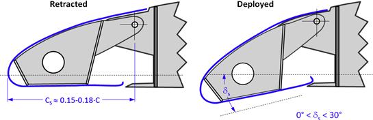
The Airload-actuated Slat (or the Automated Handley-Page Slat)
As stated earlier, the airload-actuated slat is the automated version of Handley-Page's fixed slot. It is arguably an ingenious device designed to be extracted and retracted by the magnitude of the pressure acting at the leading edge of the wing (see Figure 10-17). This way its operation is passive; when the airplane is at a low speed it is automatically deployed and when at high speed the slat is stowed, again automatically. This happens solely due to the action of pressure forces, although some designs feature a spring to help retract the slat. As the airplane must operate at higher AOAs at low speeds, a low-pressure region forms around the leading edge that pulls the element forward out of its stowed position. By the same token, when the airplane’s airspeed increases, its AOA reduces. The stagnation pressure now impinges on the element and forces it back into the stowed position. This system of passive leading edge slats is employed on aircraft like the Messerschmitt Me-262 Schwalbe, SOCATA Rallye 100 and McDonnell Douglas A-4 Skyhawk (see Figure 10-18).
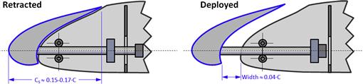

FIGURE 10-18 The airload actuated slats on the McDonnell-Douglas A-4 Skyhawk do not need a mechanical actuation system. (Photos by Phil Rademacher)
The slat travels in or out from the leading edge, but the actuation rods may be slightly curved, leading to the slat deploying out and rotating through a slight angle downward. In the deployed position, the device increases the pressure drop around the leading edge, increasing the stall AOA and CLmax of the wing. The fact that the slat retracts when the airplane accelerates to higher airspeeds reduces its drag significantly compared to the fixed slot. This renders it ideal for aircraft intended for STOL operations, but for which higher cruising speed is also important. Airplanes rolling rapidly at high speeds (fighter aircraft) have been known to occasionally have the slat on the down-travelling wing forced out, while the one on the up-travelling wing remains retracted. The resulting asymmetry may produce a violent roll departure.
The Maxwell Leading Edge Slot
The Maxwell slot is best described as an in-between the fixed slot and slat. Rather than translating and rotating like the standard (or Handley Page) slat, the device operates through rotation only about the leading edge, as is shown in Figure 10-19. From that perspective, the slat is mechanically simple, although the addition of the hinged door adds complexity. However, the cruise configuration of the airfoil is relatively smooth, although it would almost certainly trip the laminar boundary layer on both the upper and lower surfaces if used with an NLF airfoil. The position of the slat is referred to in terms of the gap opening (e.g. 0.01C or 0.0175C, etc.) rather than rotation in degrees, as this will vary based on the airfoil geometry.
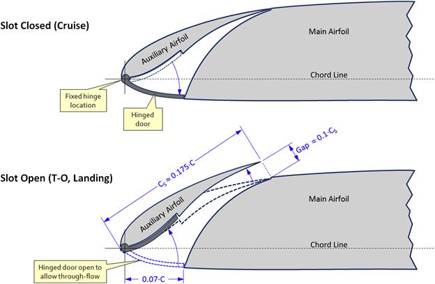
FIGURE 10-19 A schematic of the Maxwell slot. (based on Ref. [11])
The Maxwell slot can also be used without the hinged door shown in Figure 10-19. This will make its installation mechanically simpler and at first glance it will appear more like a fixed slot, however, with one important difference – in cruise, the gap size is zero, whereas it remains constant for the fixed slot. The device is investigated in Refs [11,12]. Reference [11] concludes that the increase in Clmax of a Maxwell slot is similar to that achievable with a Handley Page slat. Reference [12] found the optimum gap width to be 0.0175·C. The investigation shows that the drag of the slat increases with gap size.
Three-position Slats
The three-position slat is a version of the leading edge slat that features three positions (see Figure 10-20): retracted, take-off, and landing. In the take-off position, the slat either rests against the leading edge of the main airfoil, preventing air from flowing from the lower to the upper surface, or a very narrow slot opens. In this configuration, it works more to increase the camber of the basic airfoil, as the closed slot does not permit circulation to develop around the slat. The ideal motion of the slat is one of forward and downward motion, with limited rotation. The resulting airfoil geometry offers higher L/D than the open slot configuration and this improves T-O and climb performance. In the landing position, the slat rotates to open a slot, offering the maximum improvement in CLmax.

The track and mechanism required to move the slat in the above fashion is more complicated than shown in Figure 10-20, as such a system is biased toward translation at first and rotation later. However, many modern aircraft simply feature a circular arc design and live with a narrow slot for the T-O setting. Other aircraft, such as the B-777, have the main airfoil leading edge shaped such that it forms a seal with the trailing edge of the slat. Figure 10-21 shows the three-position slat in action on the MD-80 jetliner. The difference in slot sizes between the second and third setting is clearly visible in the center and right pictures, respectively. The three-position slat is the most common leading edge high-lift device in use today. Practically all commercial jetliners, except the B-747, use the device.
General Design Guidelines
Besides the geometry as noted, the effectiveness of the slat depends on its position and deflection as defined in Figure 10-16. The key design parameters include the chord length, CS, gap, slot width, a (which is equal to the forward translation, Δx), vertical translation, Δy, and deflection angle, δS.
Generally, the chord length should be of the order of 0.15 to 0.175C and the gap around 0.001-0.002·C. The optimum deflection is usually in the neighborhood of 25°. Figure 10-22 shows how the slat deflection angle affects the increase in Clmax. It is actually a combination of the deflection angle and the gap opening that yields the highest increase.
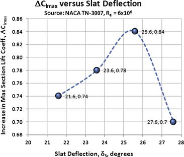
FIGURE 10-22 Change in Clmax with a slat deflection angle. (based on Ref. [1])
Note that there is a discrepancy in the literature as to how the chord length is defined. The two options can be seen in Figure 10-15 and Figure 10-19. The interested reader should refer to the cited sources to determine which applies to the published data.
Aerodynamic Properties
Results for slats and Maxwell slots using a NACA 64A010 and Clark Y airfoils are given in Table 10-1. They are obtained from Refs [1,11]. Slats yield a maximum change in maximum section lift coefficient as high as ΔClmax ≈ 0.84 for an optimized configuration. For preliminary design, numbers ranging from 0.5 to 0.7 can be used. The slats increase the stall AOA by about Δαmax ≈ 11° while the zero AOA lift coefficient drops by about ΔClo ≈ -0.21. This ignores the shift of the lift and assumes the slat will only extend the lift curve upward as shown in Figure 8-58. The minimum drag coefficient increases by about ΔCdmin ≈ 0.008 (80 drag counts).
10.2.6 Summary of Leading Edge Device Data
Table 10-1 lists important aerodynamic characteristics for a number of leading edge high-lift devices. The purpose is to provide the designer with answers to questions like – what is the change in lift, drag, and pitching moment when such devices are added to the aircraft. All data presented below is based on wind tunnel testing.
How to Use the Tables
Remember that the tables are intended to get you “in the ballpark” during the conceptual design phase. Begin by locating the part of the table containing the type of leading edge flap. Make note of the airfoil and Reynolds number used during the wind tunnel testing, as well as the flap chord and deflection. These are important values to keep in mind if the geometry and operational conditions of the target flap deviate significantly from these values. For values relatively close, it is acceptable to prorate the characteristics of interests (see Example 10-1). The values to be extracted are ΔClmax, Δαmax, ΔCdmin, and ΔCm.
EXAMPLE 10-1
A NACA 652-415 airfoil is to be used in a wing design and will feature a slat whose chord is 15% of the chord length and will be deflected to 22°. Determine the airfoil’s Clmax, αmax, Cdmin, and Cm at a Reynolds number of 6 million.
Solution
Using Table 8-5, the baseline airfoil characteristics are given by (generally, the data in the table is for Re = 6 × 10⁶) Clmax b = 1.62, αmax b = 16°, Cdmin b = 0.0042, and Cm b = −0.060.
Using Table 10-1 the following values are obtained for the slat, as tested on a NACA 64A010 airfoil.
![]()
Unfortunately, we will not be able to determine the airfoil’s minimum drag. Using the available data, we prorate the other properties as follows to account for differences in deflection and chordlength:
![]()
![]()
![]()
10.3 Trailing Edge High-lift Devices
In this section we will look at a number of trailing edge high-lift devices. Such devices are essential in reducing T-O and landing distances for aircraft. Not only do they make it possible to operate aircraft over a wide range of airspeeds; for commercial aircraft, they ultimately make or break their business case as they dictate the kind of airports the airplane can be operated from.
The purpose of the trailing edge high-lift device is to increase the maximum lift coefficient of the airfoil. Since this is accomplished by increasing the camber of the airfoil, this usually reduces the stall AOA as well. The effect is described in Section 8.3.10, The effect of deflecting a flap. Deploying a flap will affect not only Clmax and αstall but also the pitching moment and is, thus, of great importance when sizing control surfaces. The pitching moment increases substantially and this must be arrested by an adequately sized stabilizer and elevator. From an aircraft handling standpoint, deploying flaps has a major effect on the stall characteristics of the aircraft. It can also be problematic in the development of aircraft – an airplane may stall impeccably without flaps, and terribly with them deployed.
Flaps increase drag and require higher thrust to maintain straight and level flight. Naturally, this also means that the maximum level airspeed is reduced. Trailing edge devices greatly influence the distribution of lift over the wing and have a profound effect on the structural design. They develop large aerodynamic forces that must be reacted through the appropriate hard points in the wing. This also requires an increase in skin thickness to react increased wing torsion. A few small aircraft feature manually operated flaps. For such aircraft, the deflection loads are of concern and must be kept low enough to enable pilots with limited upper body strength to actuate them.
The investigation of trailing edge high-lift devices is made harder by the complexity of analysis methods. Their operation is affected by viscosity in major ways and this renders the wind tunnel as the primary methodology. Computational fluid dynamic codes utilizing Navier-Stokes solvers are making such efforts easier, although CFD should always be validated for each case using wind tunnel testing. Before the advent of such computational methods, flaps were analyzed using Glauert’s extension of the thin airfoil theory. The theory allows lift, pitching moment and hinge moments to be estimated using closed-form solutions [13].
The invention of the flap dates back to the early days of aviation. One of the earliest pieces of research can be found in Ref. [14], published in 1914. In spite of this, the flap did not become widely used until the early 1930s, when aerodynamic efficiency and wing loading had reached a state where take-off and landing speeds presented serious challenges to the operation of aircraft [15]. The trailing edge flap was a clear solution and it allowed fast aircraft to both reduce airspeed and increase the glide slope. Since then a substantial number of configurations have been devised and utilized in aircraft. The most common ones are presented here, but the reader should be aware of that more exist.
10.3.1 Plain Flap
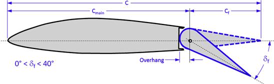
The plain flap is a simple high-lift surface that only moves through rotation without translation. It really is the simplest solution for use as a control surface, rather than a high-lift device. The control surface is effectively a semi-circle joined at the base of a triangle (see Figure 10-23). The hingeline is placed at the center of the circle, but this ensures that there will be no change in the gap between the control surface and the trailing edge of the skin of the main lifting surface element ahead of the control. This allows for a very simple and reliable control system to control the deflection of the flap, although as discussed under General Design Guidelines, the overhang (the part of the flap ahead of the hingeline) sometimes causes important complications. As such it is an effective and inexpensive means of increasing (and decreasing) lift, provided large deflections are not needed. For this reason, the vast majority of aircraft, big and small, fast and slow, feature the type for use as an aileron, elevator, and rudder control surface.
Among drawbacks is a relatively low increase in Clmax, when compared to more sophisticated flap types. As a control surface, plain flap surfaces with the hingeline at the center of the circle are difficult to mass balance and require the addition of structural arms to carry a block of mass balance. Also, a plain flap with large overhangs result in a large movement of its leading edge up and down, which requires the skin on the upper and lower surfaces to be removed to allow for this motion.
Note that the flap area is defined as the area behind the hingeline. The overhang is not a part of that area, even though it belongs to the same control surface.
The plain flap results in a relatively low increase in drag with deflection, especially for deflections in the ±10° range. It increases the airfoil camber and circulation around the airfoil, yielding higher Clmax and reduced αstall. If deflected beyond ±15°, depending on the Reynolds number, separation begins to form on the flap reducing its effectiveness (see Figure 10-24). At lower Reynolds numbers (small UAVs and RC aircraft) such separation may begin at deflection as low as ±10°. For this reason, the maximum deflection of the flap should not be greater than ±30°, because any further deflection will not yield much, if any, improvement in Clmax. Recommended maximum deflection angle is something closer to ±25°.
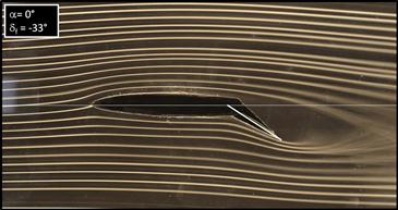
FIGURE 10-24 Streamlines show one of the drawbacks of the plain flap – massive flow separation that forms at deflection angles over 15°. This flap is deflected at 33°. (Photo by Phil Rademacher)
General Design Guidelines
The primary design variables for the plain flap are flap chord, flap deflection, hingeline location, and flap airfoil. The maximum lift of the plain flap is dependent on the flap chord, which should be of the order of 20%–30%. Some airplanes feature plain flaps for rudders with flap chords as much as 50%. The flap should be oversized by approximately 0.0003·C to 0.0030·C. Thus, if the chord is 3.28 ft (1.00 m), the over-sizing should amount to approximately 0.012′′ to 0.120′′ (0.3–3.0 mm) per side (see Figure 10-25). The purpose of the over-sizing is to re-energize the boundary layer by placing a small obstruction in its way. This helps air stay attached farther aft, improving the effectiveness of the surface at low deflections by preventing it from operating in dead air.

FIGURE 10-25 The plain flap should be slightly over-sized to help re-energize the airflow and help it stay attached.
The overhang (see Figure 10-26) plays an important role in reducing hinge moments of the flap, which is imperative if it is to be used as a manually actuated control surface (aileron, elevator, or rudder). However, this may introduce unexpected aerodynamic complexities. Let’s first consider the upper image in the figure. It shows the flap with an overhang that equals the leading edge radius of the flap. In other words, the hingeline is precisely the center of the leading edge arc. This allows the overlapping skin (or trailing edge lip as it is commonly called) to be extended so it practically touches the skin of the flap. Of course, the overlapping skin should never be in direct contact with the flap, as it flexes in flight, which can potentially lead to jamming. For many applications, the small gap may range from 0.050′′ to 0.125′′ (1.3 to 3.2 mm). A careful design of this detail will include an estimation of the most adverse structural deformation of the flap and size the gap to accommodate it. At any rate, the presence of the lip is an important advantage as this prevents a jet of air from the lower surface of the airfoil from streaming through the slot and detrimentally affecting the flow on the upper surface. Its absence can be a serious detriment to the stall characteristics of the airfoil, while its presence, in cruise, acts like a seal that reduces drag.
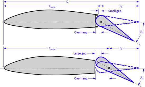
A large overhang requires the overlapping skin (trailing edge lip) to be removed. Otherwise, the leading edge of the flap will strike it and prevent further deflection. On the other hand, if the overhang is larger than the hingeline radius of the flap, the leading edge will translate with deflection as shown in Figure 10-26, and the associated (and inevitable) large gap. The presence of this gap is remedied on the Cirrus SR22 by a flexible plastic strip that is bonded to the upper surface and greatly reduces the gap size.
Aerodynamic Properties
One of the design variables is flap chord ratio. A comparison for three flap chords is provided in Ref. [13]. These are shown in Figure 10-27. Equation (10-1) is least squares fit to the data for the three flaps.
 (10-1)
where δf is in degrees. The magnitude of the Clmax using these equations is listed in the table below. It can be seen that a flap chord ratio of 0.20·C to 0.30·C will yield the highest value of the maximum lift coefficient. Reference [13] recommends 0.25·C as the optimum flap chord. The highest Clmax of the flap is obtained when it is deflected 60°. The magnitude of the Clmax was not found to vary much within the range of Reynolds numbers tested (0.6 × 10⁶ to 3.5 × 10⁶). Drag coefficients were shown to increase rapidly once the lift coefficient exceeds 1.2, which can be attributed to the increased flow separation behind the flap.


FIGURE 10-27 The maximum lift coefficient as a function of flap deflection angle and flap chord ratio.
Another aerodynamic issue is the influence of a gap between the flap and the main wing. Such a gap allows air to flow from the higher pressure on the lower surface to the upper one. This reduces the effectiveness of the flap, as is clearly shown in Figure 10-28. At a deflection of 60°, the maximum lift coefficient drops from about 2.02 to 1.65 in the presence of a 0.0032·C gap. Other data can be seen in Table 10-2.
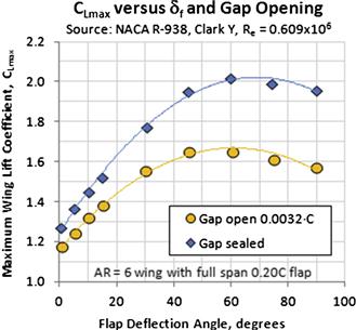
TABLE 10-2
Summary of the Aerodynamic Properties of Trailing Edge Devices


Abbreviations:
LE = leading edge
TE = trailing edge
Re test = Reynolds number during test
CS = chord of LE device
C = airfoil chord
Dbl = double
δS = deflection angle of LE device
(δf)1 = deflection of element 1 of a TE device
(δf)1 = deflection of element 2 of a TE device
Clmax = max section lift coefficient
αmax = stall AOA
Clo = lift coefficient at α = 0°
Cdmin = minimum section drag coefficient
Cmo = pitching moment coefficient at α = 0°
10.3.2 Split Flap
The split flap is really a two-member family of trailing edge flaps that consist of deflecting a plate on the lower surface without any change in the geometry of the upper surface. The two family members are called the split flap and the Zap flap.
Split Flap
The split flap is a simple flap concept that, like the plain flap, is deflected through rotation only (see Figure 10-29). It was invented in part by Orville Wright [16] and James M. H. Jacobs, who patented it jointly in 1924 under US Patent 1,504,663. Typical deflection angles range from 0° to 70°. The flap is very simple mechanically. When deployed it enlarges and magnifies the high-pressure region on the lower surface of the wing ahead of the flap, while generating a large separation region behind it. It provides great attitude and glide-slope control due to the high increase in drag without too much increase in lift or pitching moment. When used as a speed brake, it is superior to a spoiler (which is operated on the upper surface) because it increases drag without the lift reduction – it actually increases lift, but sharply reduces the L/D ratio, making the approach easier to control. The increase in Clmax is low compared to more sophisticated flap types (although arguably it is surprisingly high) and for that reason the flap is not used on any modern airliner. However, it is used on the Douglas DC-3 (C-47) aircraft and on many fighter and bomber aircraft operated during WWII: for instance, the Curtiss SB2C Helldiver and Douglas SBD Dauntless dive bombers, both of which featured split flaps with a large number of holes to reduce buffeting effects [17]. Among GA aircraft featuring the flap is the Cessna 310 and the Yakolev Yak-18T.
Zap Flap
The Zap flap is a variation of the split flap that introduces translation in addition to the rotation (see Figure 10-30). It gets its name from inventor Edward F. Zaparka, who patented it in 1933 as US Patent 2,147,360. In its simplest implementations, an actuator or a pushrod will force the leading edge of the flap backward. The presence of a special linkage forces the device to simultaneously rotate into position, increasing the chord. On a wing, it increases the wing area. As a consequence, the Zap flap generates higher lift than the split flap. The flap has not seen commercial use, but was tested in the late 1930s and early 1940s by NACA using Fairchild 22 [18] and Fairchild XR2X-1 [19] aircraft. Some results are presented below.
General Design Guidelines
Split flaps of either kind may cause severe buffeting if deployed at high airspeed, for instance when used as a dive brake. The solution is to fabricate the flap with perforations. The hinge moment of the Zap flap may reverse if there is an enlargement of the gap between the wing and the leading edge of the flap as a consequence of the flap’s translation and rotation.
Aerodynamic Properties
The split flap increases Clmax by a value ranging from 0.66 to 1.05, depending on airfoil, chord, and deflection. Generally it is deflected to an angle of 60°. The references cited showed the stall AOA to change from −1.2° to −7.2°. The change in Cm is −0.16 to −0.19. The zero AOA drag coefficient changed by some 0.1512.
The author has been unable to locate wind tunnel test data for specific airfoils featuring a Zap flap. The Zap flap was tested on a full-scale aircraft in 1942. A deployment of both the split and Zap flap leads to a relatively small shift in the stall AOA, in particular the Zap flap, which had a marginal increase in the stall AOA (which is very unusual for trailing edge high-lift devices) according to Refs [18,19].
Reference [19] found the Zap flap to increase maximum lift coefficient by 1.08 for a configuration that had a gap of 0.010C between the wing and the flap leading edge. The same flap with a gap of 0.037C increased this by 0.20. The minimum drag coefficient increased by 0.11 and the pitching moment coefficient decreased by −0.225. Other data can be seen in Table 10-2.
The data for the Zap flap pertains to a three-dimensional wing, rather than an airfoil, like the other devices in this chapter. The wing of the test vehicle had a constant chord of 4.34 ft, wingspan of 33.02 ft, and wing area of 141.5 ft2, giving it an AR of 7.705.
10.3.3 Junkers Flap or External Flap
The Junkers flap (also called the external flap) is an unusual high-lift device in the sense that it resides entirely outside the wing. Mechanically, it is a simple design (see Figure 10-31) that results in a modest increase in Clmax compared to more modern devices. However, when neutrally deflected, it even reduces the airfoil drag slightly.
The external flap is most notable for its use on the German Junkers 52-3 tri-motor military (and commercial) transport aircraft designed around 1930 (see Figure 10-32), hence its name. Additionally, it was used on the Junkers Ju-87 Stuka dive bomber. A similar device was patented by Charles E. Wragg in the USA in 1930 (U.S. Patent 1,756,272), although it is almost certain that it was conceived earlier in Germany. The device was referred to as the Wragg compound wing. Among other notable aircraft featuring the flap is the Colomban MC-15 Cri-Cri (often cited as the world’s smallest twin-engine aircraft), the Miles Gemini, and Zenith CH 701, 7050, and 801 STOL kitplanes.
FIGURE 10-32 An airworthy example of a German Junkers Ju-52 military transport aircraft featuring Junkers flap. (Photo by Nick Candrella)
The flap lends itself well for use as a flaperon, in which the outboard part of the flap combines the functionality of a flap and aileron, although as such it may suffer from excessive adverse yaw. One of the flap’s primary advantages is that it adds practically no drag to the installation and can even reduce it by a few drag counts if properly located near the trailing edge. Of course some of this is offset by the fact that the flap loads must be reacted by external hardpoints that increase the drag of the configuration. The flap does not generate a large enough Clmax on its own to be suited to the modern GA aircraft (see below), but it allows for a simple installation which may be the right choice for selected applications, as the flap resides outside the boundary layer, making it more effective at low deflection angles than identically sized conventional ailerons that are fully submerged.
General Design Guidelines
Loads are reacted by flap hinges that are mounted externally. These should be aerodynamically faired, even though this appears not to have been a concern in the design of the Ju-52. The flap was investigated by NACA in 1935 and 1936. NACA TN-524 [20] found the ideal hinge location to be 0.0125·C (1.25%) behind the trailing edge and 0.025·C (2.5%) below the chord line. These dimensions are referred to as xf and yf in Figure 10-31. NACA R-541 [21] also presents similar results, where it was remarked that this position is quite critical. The flap must be neutrally balanced, or slightly nose-heavy about the hinge line to prevent flutter. If the hingeline of the flap is close to its leading edge, an external installation of flap balance will be required and this will further increase the drag of the design.
Aerodynamic Properties
Reference [20] wind tunnel tested a Junkers flap configuration featuring a Clark Y airfoil for the main wing element and NACA 0012 for the flap element. The Clmax of the flap in the optimum location was found to equal 1.81, based on the total area, which included the combined area of the test wing element and the flap. This compares to 1.250 for the basic Clark Y at the test Re of 0.609 × 10⁶. Therefore, the increase in Clmax amounts to merely 0.56. The minimum drag of the baseline airfoil presented in the report was 0.0155, but this was shown to be reduced to 0.0146 by deflecting the flap −5° (TEU). Furthermore, a deflection angle of +5° (TED) is suggested for use during climb.
Reference [21] investigated the use of a Junkers flap using a NACA 23012, 23021, and Clark Y basic airfoils. The flap chord tested was 0.20·C and 0.30·C. The resulting aerodynamic effects can be found in Table 10-2. As one would expect, it found the optimum flap location to vary based on the airfoil, although not far from the position determined by Ref. [21].
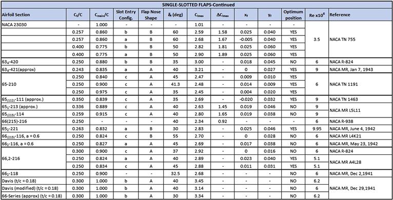
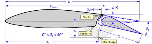
10.3.4 The single-slotted Flap
The single-slotted flap (see Figure 10-33) is an improved version of the plain flap. The flap consists of an airfoil mounted to a hinge that is offset from the main airfoil. The resulting motion combines rotation and translation and increases the airfoil chord length by some 5–10%. The motion opens a slot along the trailing edge that is imperative to the functionality of the flap. Such a translation is usually referred to as a Fowler motion, although the single-slotted flap is not regarded as a Fowler flap (see Section 10.3.6, Fowler flaps).
The general wisdom explains the increase in lift over that of the plain flaps as a consequence of the energized airflow over the plain flap. This delays separation to a higher deflection angle than is possible with the plain flap. The author prefers A. M. O. Smith’s vortex analogy [4], which also applies to leading edge devices such as slats (for instance see Figure 10-6). With respect to trailing edge flaps, the analogy considers the formation of two vortices: one on the main wing element and the other on the flap. The analogy helps explain the observed airspeed over the leading edge of the flap and the resulting low pressure peak. This fact has been well demonstrated experimentally in many of the references presented in this book. This not only explains well the increase in the Clmax but also shows that the presence of the slot is essential to the formation of the two vortices. This is important to keep in mind in the design of variable-cambered airfoils (e.g. see Section 10.2.2, Variable-camber leading edge) – such airfoils are usually designed without slots – there is no separation of the leading or trailing edge elements and, therefore, they suffer from lower Clmax that their separated counterparts.
There are a number of versions of the simple slotted flap, although only two will be discussed here: the single-element slotted flap and the single-slotted Fowler flap.
The single-element slotted flap is the most common type of trailing-edge high-lift devices used for GA aircraft. The flap features a single airfoil element of simple mechanical operation and it offers higher Clmax than the plain flap and less drag than either the split or Zap flaps. The flap is allowed to rotate to an angle as large as 50°, although such deflections result in mostly separated flow over the flap. Figure 10-35 shows the capability of a slotted flap deflected to 40°. The ΔClmax gained is 0.926.
General Design Guidelines
Some forethought must be exercised when laying out the hinge geometry. If the highest point on the flap is ahead of the hingeline when stowed, it will travel to an even higher point as it is being deployed. This may cause the flap to bind or jam in the cove, either during deployment or during retraction. This problem is compounded by the fact that the flap will flex upward when loaded. This may cause the flap to jam in flight, even if no such problems are evident on the ground. Therefore, the flight test team should try to emulate the flap flexing on the ground to avoid the problem in the air. A jammed flap may be a nuisance that requires the airplane to return to base for a repair. This is the most likely scenario. However, it is also possible it would result in a more serious flap asymmetry if the control system was fabricated such the flap on one side of the plane of symmetry could deploy fully with the other one partially deployed.
Since the presence of the slot entry (or cove entry) increases drag, there are variations of this flap that feature a cove panel to open and close it via special slave linkage. An example is shown in Figure 1.10 of Ref. [8]. The flap system should be capable of deflecting to approximately 40°, as shown in Figure 10-34. Exceeding this has limited value and may actually aggravate stall characteristics. For smaller airplanes such added complexity should be avoided. However, sealing the cove is recommended, as shown in Figure 10-36. It reduces drag considerably at typical cruise lift coefficients.
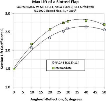
FIGURE 10-34 Typical change in the maximum lift of a single-element slotted flap, showing that Clmax occurs near a 40° flap deflection.
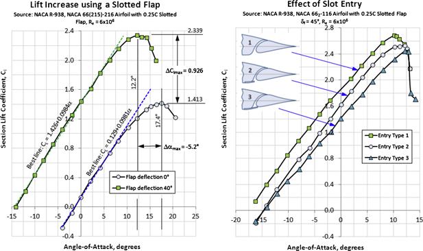
FIGURE 10-35 Typical lift gain obtained from the single-element slotted flap (left). The maximum lift is highly dependent on the cove shape (right). Rounded slot entry yields the highest maximum lift coefficient. (based on Ref. [13])
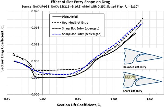
FIGURE 10-36 The effect of slot entry and slot gap seal are shown in the graph. (based on Ref. [13])
Another issue frequently overlooked is one of actuation binding, which can be caused by very high friction in the flap actuation system. Actuation binding is a serious issue as the actuation motor may not have the power to overcome the friction. It also flexes the structure and is a fatigue issue waiting to happen. It is usually a result of multiple hinges, whose hinge points are not perfectly concentric or mounted on poor foundations (e.g. flexible brackets mounted to plates rather than stiff frames and bulkheads).
Recall that at least two hinges must be used for this flap. Often, in order to minimize flap flex, three or more hinges are necessary. Mathematically, the hingeline must be a straight line that goes through all the hinges – one must be able to simultaneously look through all the hinge-holes. This means that a tight tolerance must be associated with their location – and often the only way to mount the flap is through a high-precision match drilling after the flap hinges have been installed. It is not recommended to pre-drill the hinges as their installation will not guarantee the hinge points are on the same mathematical line.
Aerodynamic Properties
The presence of the slot entry is required on the lower surface of the airfoil. This increases the drag of the airfoil with the flap stowed (see Figure 10-36) by approximately 10 drag counts (i.e. 0.0010). This should be considered the cost of doing business. The expected increase in lift, ΔClmax, should be a fairly good 0.6 to 1.0, depending on geometry and Reynolds number.
A round slot entry is recommended, although it is slightly harder to manufacture. The cost of doing business can be kept down by providing a gap seal. It does not have to be like the rubber seal indicated in Figure 10-36; it can also be a carefully sculpted wing trailing edge that practically contacts the upper surface of the flap. The drawbacks of this configuration are that the paint on the flap surface may be scraped off (can be solved with a ultra-high-molecular-weight polyethylene tape, which has a high abrasion tolerance); and that the tight fit of the upper surface of the flap to the wing on the ground may become an extremely tight fit in the air, making retraction or extension all but impossible.
The airflow through the slot is not necessarily smooth, although one would think so at first glance – this depends on the slot geometry. However, an appropriate location for a rubber seal should not be an obstruction to the flow.
10.3.5 Double-slotted Flaps
The double-slotted flap increases the maximum lift coefficient in the same way the single-slotted flap does – by delaying flow separation over the flap element. The key difference is that the double-slotted flap adds a level of boundary-layer control not possible with the single-slotted one. The extra slot allows the flap to be deflected to an even higher angle before flow becomes excessively separated. This gives a great boost to the Clmax. From a certain point of view, the flap can be considered a single-slotted flap to which a turning vane has been added to help guide the air over it. However, the vane also generates a large lift on its own. The forward of the two flap elements is called the vane and the other is simply the flap.
The term double-slotted refers to a family of two-element flaps, which not unlike the family of Krüger flaps comprises more than one type of flap. The primary difference between members is how the two elements interact. Generally, the most important design parameters are flap deflection, flap size, flap extension, and the slot geometry, which dictates how efficiently air flows through the slot. The following listing cites the most common types of double-slotted flaps.
Fixed-vane Double-slotted Flap
The fixed vane double-slotted flap (see Figure 10-37) is a version of the slotted flap in which the flow separation over the flap element is delayed by a fixed vane placed in front it. The explanation for why the fixed slot prevents the aft (or main) flap element from stalling is provided by the vortex analogy of Section 10.2.5, The leading edge slat. A vortex placed at the leading edge of each segment reduces the pressure peak, delaying the flow separation.
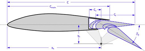
FIGURE 10-37 A schematic of the fixed-vane double-slotted flap. It can be seen that the position of the vane relative to the flap element does not change with the actuation.
The configuration increases the maximum lift of the slotted flap, but it is heavier and costlier to manufacture. However, it is lighter and less expensive than its articulating cousin, to be discussed next. The vane allows the main flap to be deflected to an angle as high as 55° before suffering reduced improvement in CLmax. The configuration increases drag over that of the single-slotted flap, even at lower deflection. This is remedied by the mechanically more sophisticated articulated vane, which is closed at low flap deflections to reduce drag and improve T-O and climb performance. The fixed vane is used on the McDonnell Douglas DC-9/MD-80 commercial jetliner, the Hondajet and the Cirrus SF50 Vision prototypes.
Articulating-vane Double-slotted Flap
There are two primary advantages of using an articulating vane for a double-slotted flap (see Figure 10-38). First, the actuation of the flap can be such that the vane closes the slot between it and the flap’s main element. This reduces the drag of the configuration, helping to improve T-O and climb performance. Second, the articulation allows an increase in the total chord over that of the fixed vane with no increase in stowed space requirements. This way the Fowler motion of the flap can be increased, which increases the maximum lift coefficient of the configuration.
The primary drawback of the articulating vane is its mechanical complexity and weight. The vanes are usually spring-loaded and rest up against a stop. Once the main element has transited backward a certain distance, the vane slot will have opened fully and the vane now begins to transit aft with the main element of the flap. The vane is attached to the flap using straight or curved tracks that are hidden in the main element.
Main/aft Double-slotted Flap
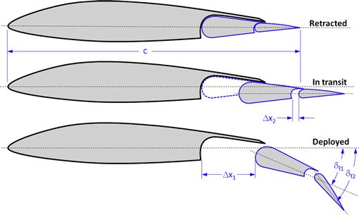
This version of the double-slotted flap is mechanically more complicated than the fixed or articulating vane flaps discussed above. This is because both elements translate and rotate (see Figure 10-39). The chord increase due to these is also greater than that of the articulating vane, yielding a slightly higher maximum lift coefficient. The forward element is the larger of the two and is now referred to as the main element. The wing overlaps the forward element, which overlaps the aft element. The forward flap typically deflects 30° to 35° (δf1) whilst the aft flap deflects 28° to 30°, or through a total deflection of 58° to 65° (δf2).
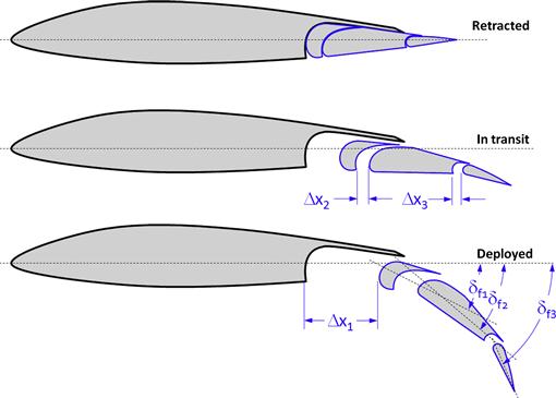
Triple-slotted Flap
It is debatable whether to consider the triple-slotted flap a variation of the slotted flap or a Fowler flap. This is due to the large translation the flap is subjected to during transit (see Figure 10-40). Typical deflection of the front element is 30°, center element 45°, and aft element 80° (approximately). The flap increases airfoil chord length and camber, yielding a large increase in CLmax, CD, and CM. A very large increase in CLmax results in substantial reduction of the stalling speed of heavy aircraft. Using A. M. O. Smith’s vortex analogy [4], there is a very complex interaction of gap jet airspeeds that combine to reduce flow separation over the elements, resulting in a high CLmax. The drag of the configuration is high, which is helpful to the pilot during the landing phase.
It is an important drawback that a very complicated and heavy mechanical system is required to deliver each flap element to its desired position. The elements must move in harmony on either side of the plane of symmetry to avoid flap asymmetry. The flaps generate very high loads that require substantial structure to support and they subject the wing to a large torsion. The flaps cause a large increase in drag, which may require high engine thrust to overcome. This can cause handling complaints if the engine spool-up time is slow. Even though the triple-slotted flap generates higher section lift coefficients than the double-slotted flap, once in three-dimensional flow it suffers from greater losses due to the flap tip vortices. The flaps result in a very large increase in pitching moment, which must be arrested by powerful stabilizing surfaces. From an operational standpoint, the mechanical system requires increased labor hours for maintenance.
Triple-slotted flaps are primarily used for commercial jetliners. Among aircraft featuring the flap are the Boeing B-727, 737, and 747. Recent advances in computational fluid dynamics (CFD) have resulted in a reduction in wing sweep that, in turn, has reduced the need for such complex flaps. Jetliners such as the 757, 767, and those made by Airbus feature the main/aft double-slotted flaps.
General Design Guidelines
Designing a multi-element flap usually takes scores of engineers. The complexity of such flaps should not be underestimated. Mechanically sophisticated flaps, which require translation and rotation, can pose a number of development issues in addition to those that have already been brought up, such as excessive play in the actuation mechanism that leads to a reduced deflection' Not to mention the possibility of a flutter problem. Issues often arise with the overlap and gap between the flap and the wing, which may change the maximum lift. There are issues with the positioning of the flap with respect to the wing, when deployed. The optimum location of the flap for maximum lift as predicted by Navier-Stokes solvers usually differs from that obtained in wind tunnel testing. If tight tolerances are not maintained, asymmetric flap deflection between the left and right sides may result and this can lead to roll-off problems when stalling in either the T-O or landing configuration. The motion of the flap must be such that the vane remains in contact with the upper wing skin (or upper cove or spoiler) for the first 15°, making it a less draggy single-element flap for the T-O configuration. Finally, the more sophisticated the flap, the more internal wing volume it tends to absorb. This will affect available fuel volume for selected applications and should be considered during the flap selection process.
Ideally, the flaps should actuate reliably and repeatedly for many years without jamming, requiring only routine maintenance, such as regular lubrication. As usual, when it comes to mechanical design, the simplest configuration that does the job is always the best one.
10.3.6 Fowler Flaps
The term Fowler flap usually refers to a high-lift device that significantly increases the chord of an airfoil in addition to rotation. They are named after the American inventor and aeronautical engineer Harlan D. Fowler (1895–1982) [22]. Reference [23] offers a fascinating insight into the development of this flap. It was invented in 1924 and was first used by the Glenn L. Martin Company, who hired Fowler to design flaps. In 1937, the flaps were introduced on the Lockheed L-14 and later on the Boeing B-29 Superfortress.
The most notable feature of Fowler flaps is the large increase in chord it provides. Since the section lift coefficient is based on the shorter stowed chord, this greatly boosts its value. It is regarded by many as the first modern high-lift mechanical flap (e.g. see Ref. [4]).
Single-slotted Fowler Flap
The single-slotted Fowler flap is generally deployed by a large translation first, followed by a rotation to as much as 40°–45° (see Figure 10-41). The translation requires the upper skin to extend much farther aft than the single-slotted flap. This means the upper aft wing skin must be stiffened in order to prevent it from bulging outward, creating a structural challenge. A single-slotted Fowler flap is used on the Boeing B-52 bomber and 747-SP commercial jetliner. A derivative single-slotted Fowler flap is used on the Cessna 152, 172, and other models under the name para-lift flaps. These translate far enough aft to justifiably be considered single-slotted Fowler flaps.

Figure 10-42 shows one way to acquire a Fowler motion for a flap design. The flap has two guide pins that move inside specially shaped flap track slots. The motion requires an actuator to move it forward and aft. That detail is left out, but can be accomplished using a linear actuator or jack-screws. The figure illustrates how the flap travels linearly about 60% of the total translation distance with merely 5° of deflection. The remaining 35° are accomplished over the remainder of the translation, resulting in substantial increase in the airfoil chord.

General Design Guidelines
A Fowler flap may present unexpected challenges. As stated earlier the upper skin that covers the flap must be stiffened to ensure it will not bulge outward due to the pressure differential between the upper and lower surfaces. This can be challenging if the flap is thick, as it will leave less thickness for structural reinforcement of the slot overlap. Play in the system can be a serious threat to the success of such flaps, as can the bending stiffness of the flap itself. These are important pitfalls. If a single actuator is used per flap side, it should be placed near the mid-span station of the flap (ideally near the center of lift). This will minimize the flap moment that could twist (or yaw) the flap around its vertical axis. Such a moment can jam the flap in the guide slots as one end moves forward (or aft), in the opposite direction to the other end. Lack of bending stiffness can flex the flap between the flap tracks so it puts undue load on the tracks or causes the flap to strike the upper surface of the wing between the tracks.
Aerodynamic Properties
Reference [24] tested two types of Fowler flaps intended for use on a GA(W)-1 airfoil; a 29% chord flap designed using a computer method developed by Lockheed Aircraft, and a 30% chord flap designed by Robertson Aircraft, a company that specialized in the manufacture and installation of STOL STCs. The smaller flap achieved a Clmax of 3.48 on the airfoil, while a Clmax of 3.80 was achieved by the 30% chord flap. A range of optimized flap positions based on deflection angle is presented in the reference. The performance gain is highly dependent on the gap and the overlap, with an optimum gap width of approximately 2.5% to 3.0% chord for the GA(W)-1 airfoil tested.
The flap increases the pitching moment by a significant value, or ΔCm = −0.75. The increase in the minimum drag coefficient amounted to ΔCdmin = 0.040, and shifted it to a higher Cl.
Among other observations made in Ref. [24], the GA(W)-1 airfoil has a prominent cusp on the aft portion of the lower surface. It was found that straightening this, as is often necessary in a production environment, led to a performance penalty at Cl > 0.8. It was also found that adding vortex generators increased Clmax by 0.2. The vortex generators increased drag at low AOAs, but decreased it at higher AOAs. Additionally, there is a negligible change in the stall AOA.
Observation indicates that a multi-element airfoil experiences two kinds of post-stall patterns referred to as an airfoil stall or a flap stall [25] (see Figure 10-43). The airfoil stall consists of the separation located mostly on the main element, whereas the flap stall resides mostly on the flap. The appearance of these is dependent on the gap between the cove and the flap, with a wide gap leading to a flap stall. The optimum gap will lead to an airfoil stall with a flow fully attached over the flap. This yields the highest maximum lift coefficient.
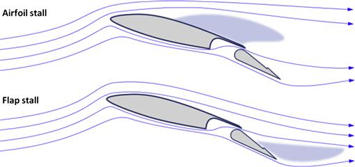
FIGURE 10-43 A flapped airfoil can stall in two ways; airfoil and flap stall. (based on Ref. [25])
10.3.7 Gurney Flap
A Gurney flap (see Figure 10-44) is a small angle added to the pressure side of the trailing edge of an airfoil and helps increase its maximum lift. The device is extremely simple to fabricate, consisting of a strip of an extruded aluminum angle or folded sheet metal. It forms a circulation pool that modifies the shape of the overall circulation over the airfoil. Considering its small size, the device increases the maximum lift substantially. Similarly it increases zero-alpha lift, or alternatively, decreases the zero-lift AOA. It also increases the wing drag. The magnitude of these increases depends on its height, denoted by the fraction h (see Figure 10-44). The flap further increases the nose-down pitching moment about its quarter-chord, offering a stabilizing effect to the aircraft if mounted to its wing.
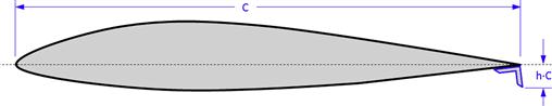
The invention of the Gurney flap is attributed to Dan Sexton Gurney (1931–) an American race car legend, who in the early 1970s used it to help increase the down-force on race cars [26]. Since then, the flap has found a variety of applications ranging from wings on race cars, wind-turbine blades, and helicopter stabilators. It can also be seen on the trailing edge of the Cessna 208 Caravan single-engine turboprop.
General Design Guidelines
Select a suitable flap height using data from the literature, for instance Ref. [27]. Note that the flap height has great impact on the drag of the Gurney flap. Refer to Figure 10-45 and Figure 10-46 for more details.
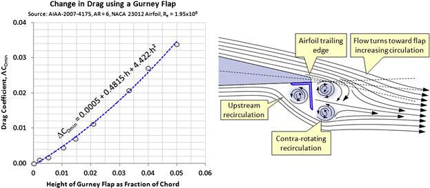
FIGURE 10-45 Drag characteristics of the Gurney flap as a function of its height (left) on a wing of AR = 6. A schematic of the flow field around a Gurney flap (right). (Both based on Ref. [27]).
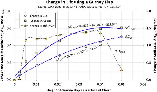
FIGURE 10-46 Lift characteristics of the Gurney flap as a function of its height. (based on Ref. [27])
Aerodynamic Properties
A large number of papers have been published on the Gurney flap. Liebeck [26] was probably the first to present information on the Gurney flap and to attempt to explain its effect. In the paper he cites early testing performed by Douglas Aircraft that seemed to indicate drag reduction, primarily for thick airfoils. However, many later publications indicate there is in fact a drag increase, at least for airfoil geometry, useful in aircraft. For example publications by Cavanaugh et al. [27] and Myose et al. [28], both demonstrate increase in CLmax and CDmin. Neuhart [29] presents an example of a Gurney flap that increased the airfoil drag at low values of CL three-fold. Similar results can be found in other papers.
Reference [27] investigated the impact of varying the height of a Gurney flap on a three-dimensional wing of AR = 6 in a wind-tunnel test whose results are presented below. The impact on lift, drag, and pitching moment observed gives a good insight into the effectiveness and shortcomings of the flap. In short, the results show that Gurney flaps increase CLmax and CLo (or decreases αZL). Furthermore, they increase CDmin, Cmo, and Cmα. Reference [29] presented pressure measurements on the upper and lower surfaces and found it to decrease on the upper surface and increase on the lower surface. This is consistent with an increase in flow circulation.
The impact on lift and drag is shown in Figure 10-46 and Figure 10-45. The latter figure also shows a schematic of the flow field around the trailing edge and how the presence of the flap changes the circulation around the airfoil by shifting the wake downward. The formulas shown in the graphs are obtained using quadratic least squares fit to the published data. They can be used to get an idea about the effect of the Gurney flap for new aircraft design. Note that these results are valid for wings of AR = 6 at a Re of 1.95 × 10⁶ and should be used with care for wing shapes and flight conditions that deviate greatly from those.
An effort has been made to reduce the drag of the Gurney flap. For instance, Vijgen et al. [30] patented a serrated trailing edge for this purpose. Mayda and van Dam [31] proposed a Gurney flap with slits. The common denominator in these designs is that the reduction in minimum drag is accompanied by a drop in the maximum lift.
10.3.8 Summary of Trailing Edge Device Data
Table 10-2 lists important aerodynamic characteristics for a number of trailing edge high-lift devices. The purpose is to provide the designer with answers to questions like: what is the change in lift, drag, and pitching moment when such devices are added to the aircraft. All data presented below is based on wind tunnel testing.
How to Use the Tables
Remember that the tables are intended to get you “in the ballpark” during the conceptual design phase. Airfoil; flap type and chord; and the Reynolds number at the flight condition must be known. Begin by locating the part of the table containing the type of trailing edge flap. Make note of the airfoil and Reynolds number used during the wind tunnel testing, as well as the flap chord and deflection. These are important values to keep in mind if the geometry and operational conditions of the target flap deviate significantly from these values. For values relatively close, it is acceptable to prorate the characteristics of interests (e.g. see Example 10-1 or 10-2). The values to be extracted are ΔClmax, Δαmax, ΔCdmin, and ΔCm. Also, make note of the geometry details shown in Figure 10-47 and Figure 10-48, which must be defined for proper referencing in Table 10-2.
EXAMPLE 10-2
A NACA 652-415 airfoil is to be used in a wing design and will feature a simple slotted flap whose chord is 30% of the chord length and will be deflected to 32°. Determine the airfoil’s Clmax at a Reynolds number of 6 million.
Solution
Using Table 8-5, the baseline airfoil characteristics are given by (generally the data in the table is for Re = 6 × 10⁶) Clmax b = 1.62, αmax b = 16°, Cdmin b = 0.0042, and Cm b = −0.060. We must use Table 10-2 to get data for the flap type selected. Unfortunately, in this case, there is only datum available to determine Cl max. The other parameters will have to be determined by other means, e.g. the methods of Section 15.5.8, Drag of deployed flaps.
Looking through the data of Table 10-2 it can be seen there are two 65-series airfoils that feature a single-slotted flap and are “reasonably” similar to 652-415 airfoil (NACA 651-213 and 65(215)-114). Here we will use the latter. However, the increase in the maximum section lift coefficient is based on testing at Re = 9 × 10⁶, which is one-third greater than our target Re of 6 × 10⁶. This exposes one of the problems with using test data for dissimilar airfoils exposed to dissimilar flight conditions: applicability. However, in the absence of more direct data, Table 10-2 is our best bet but calls for a sound engineering judgment. If possible, adjust the Clmax to the appropriate Reynolds number. Here assume the Clmax at 6 million to be 90% of that at 9 million. Using Table 10-2 the following values are obtained for the 65(215)-114 airfoil:
![]()
Therefore, we can estimate the maximum section lift coefficient as follows:
![]()

FIGURE 10-47 Reference geometry schematics for slotted flaps for Table 10-2.
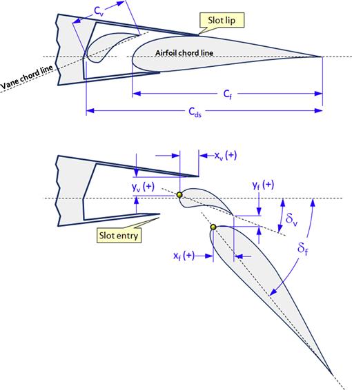
FIGURE 10-48 Reference geometry schematics for double-slotted flaps for Table 10-2.
10.4 Effect of Deploying High-lift Devices on Wings
The purpose of this section is to provide methods that help the designer estimate the impact of deploying high-lift devices on a three-dimensional wing. The characteristics of interest usually include the maximum lift coefficient, lift curve slope, stall AOA, minimum drag, and pitching moment. In this section, a method to estimate the lift and pitching moment of a wing with deployed high-lift devices will be presented. A method to estimate the drag is presented in Section 15.5.8, Drag of deployed flaps.
The analysis methods presented use the dimensioning scheme shown in Figure 10-49. The subscript ‘s’ stands for slat and refers to any kind of a leading edge high-lift device. The subscript ‘f’ stands for flap and can refer to any kind of a trailing edge high-lift device.
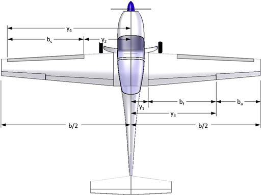
FIGURE 10-49 Layout and important dimensions of a typical aircraft with partial span flaps and slats.
10.4.1 Lift Distribution on Wings with Flaps Deflected
Partial Span Flaps
Figure 10-50 shows the spanwise distribution of section lift coefficients with partial span flaps deflected 0°, 10°, 20°, and 30°. It is based on potential flow theory. The figure shows that the spanwise change in Cl over the wing is not instantaneous, but gradual. The coefficients begin to rise well outside the flap’s root and tip. This is caused by the increased circulation around the flap, which increases the upwash in the flow field outside the flap ends. The figure also shows how the upwash complicates stall tailoring efforts, as the increase in section lift coefficients on the outboard wing will cause early flow separation in that area of the wing.
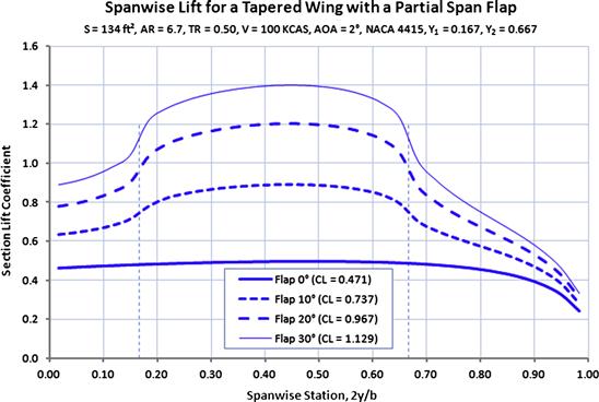
Full Span Flaps – Flaperons
Full span flaps, as the name implies, extend from the inboard wing to the wingtip. Such devices substantially increase the total lift capability of the wing, although they may introduce new problems not present in the unflapped wing. First, in order to maintain roll control, aileron functionality must be introduced to the flap control system. This is usually solved by splitting the flap into inboard and outboard segments. Then, the outboard segment is designed to function as both a flap and an aileron. Such a control system configuration is referred to as flaperons.
A second drawback stems from the fact that, when deployed, the overall spanwise distribution of section lift coefficients is modified (see Figure 10-51). This may cause roll instability at stall for the flapped wing, even when there are none present for the unflapped configuration. The problem is compounded by the fact that roll control requires one flaperon to be deflected to an even greater angle than the rest of the flap. This can lead to premature aileron stall at low speeds and high AOA, just when they are needed the most. The de Havilland of Canada DHC-6 Twin Otter is an example of an aircraft that features such flaps and solves this by varying the deflection of the flaps. This is readily evident from its TCDS [32], the deflection of its double-slotted flaps varies as shown in Table 10-3.
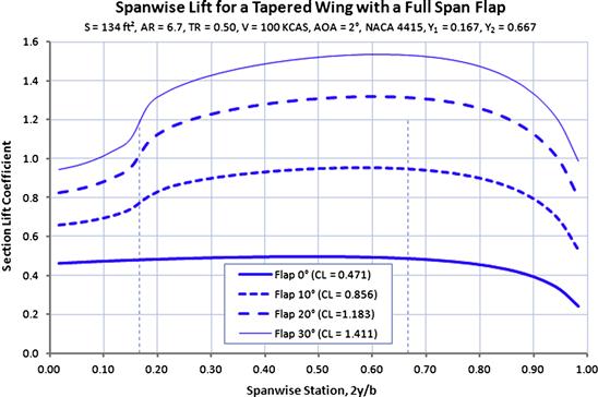
FIGURE 10-51 Spanwise distribution of section lift coefficients for full span flaps (e.g. flaperons) (Cf/C = 0.30).
TABLE 10-3
Deflection Characteristics of the DHC-6 Twin Otter Flaperons
| Flap | Inboard element | Outboard element |
| Forward element | 0° to 40° | 0° to 26° |
| Aft (trailing) element | 0° to 62.5° | Aileron (flaps up): Up 17.5°/Down 16.0° Aileron (flaps dn): Up 25.0°/Down 17.5° |
Thus, while the aft inboard trailing element deflects to 62.5°, the aileron (which is the trailing element of the outboard flap) is limited to 26° + 17.5° = 43.5°. Helped by the presence of a slot in the flap, flow separation is kept to a minimum. A third drawback is adverse yaw. The down-deflected aileron element, of course, is associated with the wing that rolls up and this adds substantial drag to the outboard wing. The opposite happens on the wing that rolls down; comparatively substantial reduction in drag. The combination may cause a noticeable adverse yaw that must be eliminated by assertive rudder deflection.
10.4.2 Wing Partition Method
In order to better estimate lift and pitching moments resulting from the deployment of various high-lift devices, it is common to use the wing partition method. The method is more or less a derivative of the blade element theory (BET) presented in Section 14.6. The method partitions the wing into the segments shown in Figure 10-52 and, then, the aerodynamic properties of the individual segments are estimated and used to calculate the total of the wing. The partitioning makes it is much easier to manage the change in aerodynamic properties. The scheme presented here is only for demonstration. Your airplane may be more, or less complicated. A demonstration of the method is presented in Example 10-3.
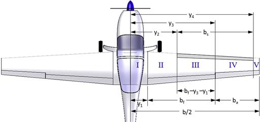
The first step is to tabulate the geometric properties of each segment, using a table similar to Table 10-4. These are then summed in accordance with the formulation presented below (here shown listing four segments). An example of its use is shown in Example 10-3.
TABLE 10-4
Wing Geometric Properties Based on Segment

where Ya = distance of the inboard end of the segment from the plane of symmetry
Yb = distance of the outboard end of the segment from the plane of symmetry
Si = trapezoidal planform area of the segment
Λhingeline = hingeline angle (with respect to a vector normal to the plane of symmetry)
Clmax a = maximum lift coefficient at the inboard end of the segment
Clmax b = maximum lift coefficient at the outboard end of the segment
ΔClmax = increase in maximum lift coefficient due to a high-lift device
Clmax avg = average of Clmax a and Clmax b
Estimation of the Maximum Lift Coefficient
The following expression, in effect, is the BET variation used to estimate the maximum lift coefficient:
![]() (10-2)
(10-2)
where
Nf = number of flapped wing segments
Nuf = number of unflapped wing segments
Clmax i = maximum lift coefficient of the flapped wing segment
Cli = average lift coefficient of the unflapped wing segments at the stall AOA of the flapped one
Λhingeline = angle of the hingeline to a normal to the plane of symmetry
The factor 0.9 is used to account for three-dimensional effect. It is imperative to account for the detrimental effects of hingeline sweep. Note that even straight-tapered wings will be subject to it, unless of course the planform is laid out such that the hingeline is perpendicular to the plane of symmetry.
Estimation of the Pitching Moment Coefficient
Since the pitching moment of an airfoil, effectively, is the product of the lift it generates and its location on the airfoil, it is possible to approximate the total pitching moment of the wing in a manner similar to that presented in Equation (10-2):
![]() (10-3)
(10-3)
where
N = total number of wing segments
Cm i = average pitching moment coefficient of each wing segment, flapped and unflapped
EXAMPLE 10-3
Estimate the maximum lift coefficient for the SR22 using the wing partition method. The aircraft features single slotted flaps that deflect to 32°. Its reference area is 144.9 ft2. Assume a NACA 652-415 airfoil for the entire wing (although this is not the case for the real aircraft). Use data from Table 8-5 for the airfoil. The pertinent dimensions for the wing are shown in Figure 10-53, where:
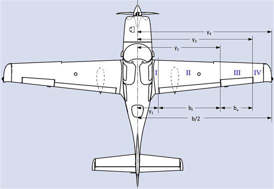
Use the equation of the chord given for the SR22 in Section 16.5.1, Cirrus SR22, given by 5.160 - 0.1342·y (ft). Compare the value to the POH value, which is shown to be 1.99 in Table 16-6.
Solution
It is a tad tricky to find data specifically using the NACA 652-415 airfoil. Ultimately, we will have to use hybrid data, i.e. splice together a data set using airfoils that “resemble” the 652-415. First retrieve information from Table 8-5, from which the stall AOA, zero lift AOA, and lift curve slope for the airfoil are found to be as follows:
![]()
Next, resort to Table 10-2 for a single slotted flap on airfoils similar to the 652-415. One of the airfoils is the NACA 65(215)-114, detailed in NACA MR L5L11. We will consider it “close enough” to use in this example. Researching the sources gives the following information. Figure 9 of the reference (i.e. NACA MR L5L11) shows a Clmax of about 2.80 for 32° of flap deflection at a Re = 9 × 10⁶. Figure 10 shows that (fortunately) there is not a large reduction in Clmax by lowering the Re to 3 × 10⁶ (although there is a huge drop when one goes to 1 × 10⁶). We will, thus, use the value of 2.80, however, to be conservative, we multiply it by 0.95. Therefore, consider Clmax = 0.95 × 2.80 = 2.66. Figure 8 of the reference document also shows the stall AOA to change by 4°, from 14° for the unflapped airfoil, to 10° for the flapped airfoil. Using this data we now rewrite the properties as follows:
![]()
![]()
We will not need all of the above information, but it is good to have nevertheless. Next determine the AOA of the unflapped airfoil when the flapped one stalls. To do this we resort to Equations (8-10) and (8-11), i.e.:
![]()
We now have enough information to begin to populate Table 10-4. First, take care of the initial geometry as shown in Table 10-5. Columns ![]() and
and ![]() are the spanwise stations in units of ft (i.e. distance from the plane of symmetry) that enclose the corresponding wing segment. Columns
are the spanwise stations in units of ft (i.e. distance from the plane of symmetry) that enclose the corresponding wing segment. Columns ![]() and
and ![]() are the chords at those stations in ft. Column
are the chords at those stations in ft. Column ![]() is the average of the two chords; and Column
is the average of the two chords; and Column ![]() is the planform area of the segment.
is the planform area of the segment.
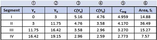
Table 10-6 presents the analysis necessary to determine the maximum lift coefficient. It is ideal to review Equation (10-2) to recall the variables that must be included. The first three columns correspond to Columns ![]() ,
, ![]() , and
, and ![]() of Table 10-5 and are merely here for reference. Column
of Table 10-5 and are merely here for reference. Column ![]() is the hingeline angle (assumed 4° for the flapped section). Columns
is the hingeline angle (assumed 4° for the flapped section). Columns ![]() and
and ![]() are the maximum lift coefficients estimated at the two spanwise stations Ya and Yb. It is simply a linear interpolation of the Clmax for the unflapped airfoils at the root and tip. Column
are the maximum lift coefficients estimated at the two spanwise stations Ya and Yb. It is simply a linear interpolation of the Clmax for the unflapped airfoils at the root and tip. Column ![]() is the increase in the Clmax of the segment due to the deflected flap. Here, it can be seen that only Segment II has an associated increase, as this is where the flap is. Column
is the increase in the Clmax of the segment due to the deflected flap. Here, it can be seen that only Segment II has an associated increase, as this is where the flap is. Column ![]() is the average of the maximum lift coefficient of the airfoils at stations Ya and Yb. Finally, Column
is the average of the maximum lift coefficient of the airfoils at stations Ya and Yb. Finally, Column ![]() is the segment weighted value of the average maximum lift coefficient of the segment; i.e. the larger the segment area, the greater is its contribution to the total CLmax.
is the segment weighted value of the average maximum lift coefficient of the segment; i.e. the larger the segment area, the greater is its contribution to the total CLmax.
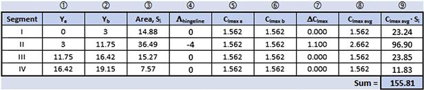
Then, the maximum lift for the airplane can be determined using Equation (10-2) as shown below:
![]()
The factor “2” is there to account for both wing halves, but the formulation in Table 10-6 only treats one wing half. The result is about 97.3% of the POH value of 1.99 (see Table 16-6) – not too a bad an agreement at all.
10.5 Wingtip Design
One of the most noticeable features of aircraft is the variety in their wingtip shapes. Wingtips come in all shapes and sizes, begging the question – do wingtips have an important role to play when it comes to aerodynamics, or are they primarily another expression of aesthetics? The answer to both questions is yes. Wingtips can offer fundamental improvements in efficiency and handling, but they are sometimes also selected for appearance. A large number of wingtip styles have been devised – we will only present a few and the most common ones here and primarily discuss their effectiveness from an aerodynamic standpoint. The looks are left to the reader to judge.
The literature shows that the shape of the wingtip affects both the minimum and lift-induced drag [33]. For instance, a square wingtip (see Section 10.5.3, The square wingtip) has a higher minimum drag than a spherical tip (see types below). However, the square tip results in less lift-induced drag than the spherical tip. This reduction is attributed to a distortion in the flow field that brings the wingtip vortices either closer or farther from the plane-of-symmetry. The greater the separation, the greater is the “apparent” AR of the wing and the less the lift-induced drag. Hoerner [34] states that the separation of the wingtip vortices “does not coincide with the geometrical span,” but depends on the shape of the wingtips.
An example of this is shown in Figure 10-54. It can be seen that the round-shaped wingtip (as seen when looking at the front) results in the highest drag. Although the difference at low lift coefficients is small, it grows rapidly enough to yield a measurable reduction in rate of climb and maximum lift-to-drag ratio.
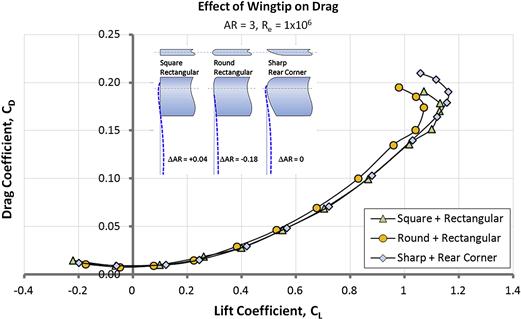
FIGURE 10-54 The effect of wingtip shape on the drag polar. The effect holds for higher AR wings as well. Note that the “Sharp + Rear Corner” wingtip is a “Hoerner” wingtip. (based on Ref. [35])
Aerodynamic Effectiveness of Wingtips
An important element in the installation of wingtip devices is an evaluation of their effectiveness. Low-speed characteristics, such as claims of improvements in stall handling, are difficult to measure. Any anecdotal claims of this must be regarded with great skepticism, in particular if they are associated with the marketing of aftermarket products. High-speed effectiveness is easier to measure and this is usually done by measuring the impact on lift-induced drag. This allows effectiveness to be stated in terms of something relatively easy to relate to, such as an effective change in AR, denoted by ΔAR. Thus, the value of a specific wingtip device can be evaluated by accounting for it when estimating drag in performance analyses. This can be done by simply adding ΔAR to the reference AR in the standard aircraft drag model (see Chapter 15, Aircraft drag analysis).
In real applications, the addition of a wingtip device affects more than just the lift-induced drag. For one, it always adds surface area and, thus, it increases wetted area. Additionally, some wingtips, such as endplates, also increase interference drag. An example of the combined effect of installing a typical winglet is presented in Figure 10-71. The cost of reduction in the lift-induced drag usually comes at a cost of higher parasitic drag. Since the parasitic addition is so highly dependent on the aircraft itself, we will only consider the effect on the lift-induced drag here. The goal is to modify the lift-induced drag as follows:
![]() (10-4)
(10-4)
where AR is the aspect ratio of the original (or baseline) wing, CL is the lift coefficient at some reference flight condition, and e is the Oswald span efficiency of the original wing. Assume further that we modify the baseline wing by mounting a wingtip device, whose addition to the wingspan is given as Δbt at each wingtip. While this increases both the wingspan and wing area, we will consider both the reference span and area to be unchanged. Additionally, we consider the difference in the Oswald efficiency of the two wing styles to stem solely from the addition of some finite aspect ratio, ΔAR, to the baseline AR. This can be justified based on the observation that as far as lift-induced drag is concerned, it is the product AR·e that matters and not AR or e on its own. Therefore, we can either modify AR, or e, or the product of the two. Here, however, for convenience, we will consider this change in terms of the AR as it is easier to relate to, as stated above. The gain in AR is calculated from:
![]() (10-5)
(10-5)
Derivation of Equation (10-5)
The purpose of the formulation is to apply it to an airplane being operated at some desired CL so the wingtip style being considered can be compared to the baseline wing. For this reason, we can specify the two following condition at some given lift coefficient, CL:
![]()
![]()
This shows that the difference in lift-induced drag is given by:
![]()
Solve for ΔAR:
![]()
QED
10.5.1 The Round Wingtip
The round wingtip, shown in Figures 10-55 and 10-56, is one of the oldest and simplest ways to terminate the wing at the tip. It consists of a semi-circular edge that extends from the leading to the trailing edge. The wingtip has been around since the 1920s. Hoerner [34] demonstrated it is less effective than once thought, as the wingtip vortex tends to move onto the upper surface. Consequently, the effective AR is in fact reduced. This means that when working with a specific AR in drag or stability and control analyses, the AR must be reduced by as much as 0.20.
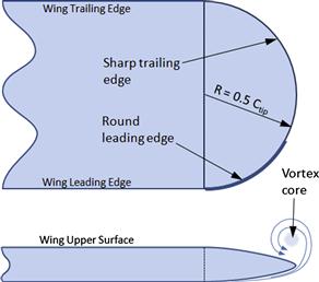

FIGURE 10-56 A Beechcraft D-18 boasting its round wingtips. The twin vertical tail surfaces, effectively, are endplates for the horizontal tail. (Photo by Phil Rademacher)
The effectiveness of the tip is overestimated by potential flow theory, which renders it more effective than either a square or the spherical wingtip (see Section 10.5.10, Comparison based on potential flow theory). This can be explained by increasing section lift coefficients near the rapidly tapering tip, which at cruise AOA makes the configuration more efficient. However, this is contradicted by the results of Ref. [34], which are based on wind tunnel testing.
10.5.2 The Spherical Wingtip
The spherical wingtip, shown in Figure 10-57, is a simple and commonly used termination of the wing at the tip. It is simple to fabricate using composites and poses minimal challenges in the layout of its loft. Its planform view of the curvature is usually governed by the airfoil, as the geometry is a semi-circle along the tip chord.
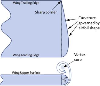
Zimmer [36] refers to the wingtip under the name Goettinger wingtip, but the author has been unable to confirm that name.
Aerodynamically, the spherical tip is an inefficient shape, as it causes the wingtip vortex to roll up and inboard, as shown in Figure 10-58. This reduces the separation between the two wingtip vortices, which leads to a reduction in the effective AR (see Figure 15-69) and increased lift-induced drag.
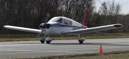
FIGURE 10-58 A Piper PA-28 Cherokee four-seat, single-engine sport aircraft featuring round wing tips. (Photo by Phil Rademacher)
The geometry has no influence on dihedral effect. However, it is thought to have a detrimental effect on spin characteristics due to the formation of a low-pressure region around the wingtip, which helps drive the autorotation and, thus, can render spin recovery more difficult.
10.5.3 The Square Wingtip
The square wingtip (see Figure 10-59) is the simplest geometry possible for a wingtip. The sharp termination forces the wingtip vortex to form and reside on the outboard side of the tip (rather than above, as for the round tip). This effectively pushes the wingtip vortices farther apart from the centerline of the aircraft and increases the effective AR, albeit by a small amount. This, at least theoretically, reduces lift-induced drag by a small amount (see Section 15.5.18, Corrections of the lift-induced drag). The tip has no influence on dihedral effect. An example of a square wingtip is shown in Figure 10-60.
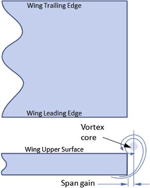
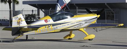
10.5.4 Booster Wingtips
Booster wingtips are noticeable by their distinct trailing edge curvature, which comes in two forms; upturned and downturned (see Figure 10-62 and Figure 10-63). Both are intended to bring the wingtip vortices farther outboard, increasing effective AR and, in that way, reducing the induced drag. The true effect on drag is not well known, although some manufacturers of aftermarket booster wingtips claim benefits such as low-speed roll stability and reduction in stalling speed. The author has been unable to locate any published papers that support such claims. The characteristics of the booster wingtip will now be discussed.
The Upturned Booster Wingtip
The upturned booster wingtip consists of geometry in which the lower and upper surfaces join in a sharp termination, or edge, that flares upward at the trailing edge, as shown in Figure 10-61 and Figure 10-62. The wingtip style is most easily made from composite materials, although the sharp edge sometimes requires fabrication techniques that minimize the formation of production nuisances such as dry fibers and “bridging.”


FIGURE 10-62 A Cirrus SR22 four-seat, single-engine, high-performance aircraft, featuring upturned booster wingtips. (Photo by Phil Rademacher)

FIGURE 10-63 A Cessna 206 six-seat, single-engine, high-performance aircraft featuring downturned booster wing tips. (Photo by Phil Rademacher)
Theoretically, the wingtip increases the separation of the wingtip vortices and, therefore, increases the effective AR. In practice, the increase is probably negligible. It also increases dihedral effect by a small amount.
The Downturned Booster Wingtip
The downturned booster wingtip is effectively an inversion of the upturned style. Just like the upturned booster tip, there is not much to be found in the literature regarding improvements in effectiveness (e.g. see Rokhsaz [37]). Naik and Ostowari [38] present an experimental investigation of several non-planar wingtip configurations, including a downturned droop. The results provided show limited to no benefit over the planar reference wing. In accordance with standard lateral stability theory, the downturned booster wingtip decreases dihedral effect, i.e. roll stability. However, there is a perception they improve handling near stall and, thus, have been marketed as a part of short t-o and landing (STOL) STCs for low-speed aircraft. Other schools of thought claim they have a detrimental effect on spin characteristics as a low-pressure region is formed around the wingtip, which will help drive autorotation and, thus, can render spin recovery more difficult.
10.5.5 Hoerner Wingtip
The Hoerner wingtip is named after the German aerodynamicist Sighard Hoerner (?–1975) who showed its effectiveness to be superior to that of the round wingtip. In fact, its primary advantage is that its impact on the effective AR is neutral, rather than negative like that of the round wingtip (see Section 15.5.18, Corrections of the lift-induced drag). Hoerner wingtips are used on a number of aircraft, most notably the Grumman American AA-5 series of aircraft, produced between 1971 and 2005 (see Figure 10-64).
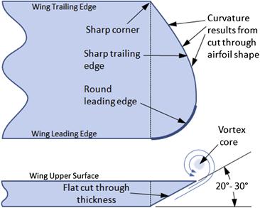
The wingtip increases dihedral effect. Theoretically, it is intended to shift the wingtip vortex farther outboard and this requires a sharp edge separating the upper and lower surfaces along the aft trailing edge as shown in Figure 10-65. Normally, the first part of the leading edge features a round geometry to prevent the upper surface from stalling at low AOAs.
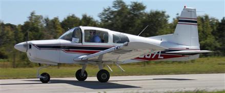
10.5.6 Raked Wingtip
The raked wingtip is a very efficient means to increase the effective AR. Its primary drawback is that it comes at the cost of increased wingspan and wing bending moments. The wingspan increase may spur parking and hangar space challenges, whereas the increase in bending moments will raise the airframe weight. It is an advantage that the device does not increase parasitic interference drag, although it will increase skin friction if it is an addition to an existing wing baseline. An example of a raked wingtip is shown on the Boeing 777 commercial transport aircraft in Figure 10-66. Such wingtips have also been used on the Boeing 767 and 787 Dreamliner aircraft. Their use in GA aircraft, at this time, is rare. The best example is the Coast Guard surveillance version of the Schweizer SGM 2-37 motorglider, called the RG-8A.
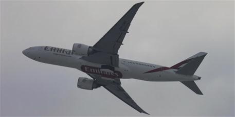
FIGURE 10-66 A Boeing 777 commercial transport aircraft, operated by Emirates, featuring a raked wing tip. (Photo by Phil Rademacher)
Contrary to popular belief, raked wing tips have a long history, having been first evaluated in 1921 in NACA TN-69 [39]. Both positive (forward sweep) and negative (aft sweep) rakes were studied and it was found that the maximum L/D ratio at an AOA of 4° increased by 7%. Interestingly, the best result was that of a 20° positive rake. The report concluded, “the effects of rake on the lift and drag are so small that considerations of strength and aileron efficiency should govern the wing tip form.” This interesting conclusion highlights the difference in the airplane designs of the 1920s and 2010s – today, 7% translates into substantial fuel savings – which was much less of a problem in the early twentieth century.
The effectiveness of the raked wingtip depends on the rake angle, φ, but also on its own dihedral angle, Γ, and span, Δbt (see definitions in Figure 10-67). Based on potential flow theory, the dihedral angle should be around 4–8°, depending on wing geometry. A very high or low dihedral (±10° and greater) will actually increase the lift-induced drag. An example of this is shown in Figure 10-68. The graph compares three raked wingtip styles to a baseline Hersey-bar wing of AR = 6. All the configurations have the same total wingspan and the raked tip span is Δbt = 0.125b. For this reason, the wing and wetted area of the baseline wing are larger than those of the other configurations, called Tip A, Tip B, and Tip C. Tip A has a 5.71° dihedral, Tip B has a 26.57° dihedral, and Tip C has a 26.57° anhedral. It can be seen that Tip A (sometimes referred to as the Trilander wingtip, as in Britten Norman Trilander) generates the least lift-induced drag of the four wing styles, in addition to having the least wetted area. This indicates it is the most efficient wing style of the four. Tips B and C generate precisely equal lift-induced drag and both are substantially less efficient in cruise than either the baseline or Tip A. This result also shows that designing a raked wingtip requires careful evaluation of the geometry.

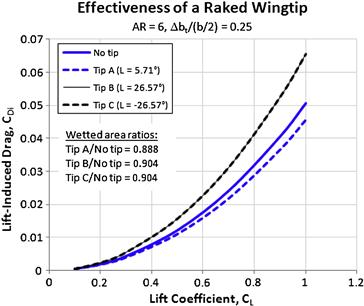
FIGURE 10-68 An example of a raked wingtip shows that a low dihedral decreases lift-induced drag, while a larger dihedral increases it.
Gain in effectiveness depends on the details of the geometry, but expect ![]() and possibly higher than
and possibly higher than ![]() for well optimized wingtips. For instance, Tip A in Figure 10-68 achieves a ΔAR of around 0.88 without any optimization.
for well optimized wingtips. For instance, Tip A in Figure 10-68 achieves a ΔAR of around 0.88 without any optimization.
Rakelet
The Rakelet is a combination of the raked wingtip and a winglet, and is considered a new wingtip device. Investigated as a proposal for the KC-135 Stratotanker, by Diaz et al. [40], it is claimed to improve its range over that of the baseline wing by as much as 7.5%.
10.5.7 Endplate Wingtip
It was recognized early on that drag did not just depend on the geometry of the body, but also increased rapidly with AOA. The discovery of the endplate is attributed to the British scientist Frederick W. Lanchester (1868–1946), who discovered that vertical plates positioned at the tip of a lifting surface greatly improved its lift. Other serious studies date back to the early 1920s with the work of Reid [41]. The endplate has a similar effect as placing a wing section from wall-to-wall in a wind tunnel – it makes it behave more like a two-dimensional airfoil. The consequence is an increase in section lift coefficients, lift curve slope, and maximum lift coefficient [42]. It also reduces the lift-induced drag. Examples of theoretical treatment of lift and drag endplates are given in Refs [43, 44, 45].
Endplates have a number of drawbacks. First, the surface adds parasitic drag through increase in wetted area and interference drag where the plate joins the lifting surface. The combination cuts into the aerodynamic benefits and may even exceed the reduction in lift-induced drag. Second, the inertia of the endplates not only increases the weight, it also reduces the natural frequency of the lifting surface, which makes it more susceptible to flutter. To solve this issue, the lifting surface must be stiffened, which further adds to the weight. Third, if the endplates are used as a vertical tail and include two rudders, a more complicated control system is required. Fourth, in a production environment, using two vertical surfaces for a VT, rather than one, increases manufacturing complexity.
In spite of these shortcomings, endplates have been widely used in the aviation industry. Airplanes dating from to the 1930s and later, frequently featured the configuration as horizontal and vertical tail surfaces. During the Second World War, a large number of multiengine bombers and transport aircraft were designed with twin tails, which was helpful in an environment in which ‘losing’ an engine was a likely scenario. Immersing the two tails in the propwash of operational engines improved not only controllability, but survivability. The most recent example of such use is the tail surfaces of the Russian military transport aircraft Antonov An-225 Mriya, currently the world’s heaviest airplane with a 1.41 million lbf gross weight. This design solution helps to keep the overall height of the aircraft down, allowing it to be stored in existing hangars for maintenance. Endplates are also used in place of a winglet on the Airbus 320 family of commercial jetliners (see Figure 10-69).
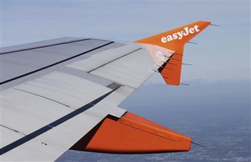
The magnitude of the effect is highly dependent on the height of the endplates, as shown in Figure 10-70. When used on a horizontal tail, the endplate allows for a smaller horizontal tail surface, improved elevator effectiveness and the endplates serve well as vertical tails.
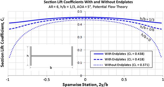
FIGURE 10-70 Comparing the distribution of section lift coefficients with and without endplates shows great improvement in surface lift effectiveness depending on endplate height.
Gain in effectiveness (see Equation (9-88)):
![]()
10.5.8 The Winglet
From a certain point of view, the winglet is a sophisticated mutation of the endplate discussed above. As stated earlier, there are several drawbacks to the use of endplates. These detriments are lessened using winglets. Since winglets are often not completely vertical, and largely above the wing plane, they can increase the lateral stability derivative (Clβ or dihedral effect) over that of the endplate. This may aggravate the Dutch roll damping, but can also affect the cross-wind capability of the aircraft. Of course, the endplate and winglet both increase the side force derivatives, Cyβ. Winglets also pose structural ramifications if added to airplanes not originally designed with them. They increase the wing bending moments and lower the flutter speed (albeit less than endplates). But one of the most important differences between a ‘clean’ wing and one with winglets is in the nature of drag, as will now be explained.
Adding a winglet to an airplane increases two types of drag – skin friction and interference drag. They only reduce the lift-induced drag – when properly designed. In fact, they can easily increase the total drag. They are aerodynamically viable only when the reduction in the lift-induced drag is larger than the increase in the skin friction and interference drag. This is illustrated in Figure 10-71, which compares the potential installation of winglets on a Cirrus SR22 style aircraft to the original clean wing. While the numbers are “pulled out of thin air” (except the CDmin of the original configuration, which is calculated in Example 15-18), they still represent a realistic scenario. The presence of the winglet is treated as an increase in the original AR and CDmin. Figure 10-71 shows that when operating at CL < 0.55 (e.g. at cruise), the total CD of the original airplane is actually lower than with the winglet. If operating at CL > 0.55 (e.g. during climb) the total drag will be reduced over the original wing. It is easy to determine from its POH that the SR22 cruises at CL ranging from 0.17 to 0.30. Therefore, a winglet installation would have to be justified on other merits, such as cosmetics or improved climb and T-O performance. Of course, this does not deny that certain winglet geometry may exist that moves the break-even point below what is shown in the graph.

FIGURE 10-71 A comparison of drag polars before and after a winglet has been installed, helps explain their benefits. The thin dashed curve is the drag polar for the original wing, the solid thin curve represents the wing with the winglet, and the thick solid line is the difference between the two.
Another interesting lesson evident in Figure 10-71 is that the winglet only shaves off a few drag counts. For instance, at CL = 0.8 it reduces the drag by 12 drag counts. Compare that to 254 drag counts of the original aircraft (4.7%). At CL = 0.3 the opposite holds true; the drag is increased by 8 drag counts. Another way of interpreting this difference is that the airplane may have to climb to a high altitude (where it would have to cruise at a higher AOA) in order for the winglets to be justified based on drag reduction. If the same airplane is cruising in denser air, it will do so at a lower AOA and, thus, with drag penalty.
Like the generation of lift, the workings of a winglet can be explained in a number of ways. The author’s favorite explanation is that the magnitude of the section lift coefficients near the wingtip increases due to an enlarged low-pressure region generated inboard of the winglet. The resulting lift distribution resembles that of a wing with a larger AR than indicated by the plain planform geometry.
This, in effect, reduces CDi for the same CL. This view explains why the winglet has to be ‘loaded up’ in order to function. “Loaded up” simply means it must be placed at a relative AOA large enough to generate lift and, that way, boost the low-pressure region near the wingtip. For this reason the angle-of-incidence of the winglet must be placed at a specific “toe-in” or “toe-out” angle (Figure 10-72), depending on geometry. An unloaded winglet will not reduce the lift-induced drag because its contribution to the low-pressure field is negligible.
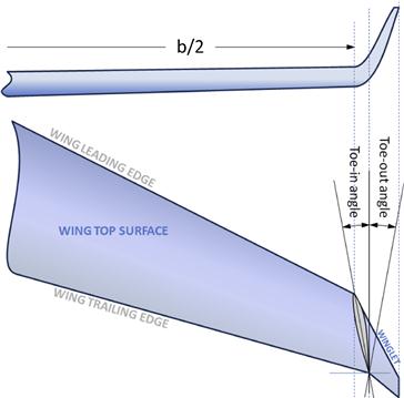
Another explanation attributes the reduction in the lift-induced drag to the distribution of the sheet of trailing vortices over greater distance, making it better resemble that of an elliptic planar wing (which has the minimum lift-induced drag). An insightful reasoning is provided by Hoerner [35] and McCormick [46], who explain it as the consequence of the lift force acting on the winglet surface, which is tilted forward due to the local AOA on the winglet. This way, the lift of the winglet, effectively, generates a forward force component – thrust – that can be subtracted from the drag. This perspective allows formulation to be derived to estimate the drag reduction. Regardless, all these explanations are different sides of the same box.
Gain in effectiveness can be approximated using the following expression, by assuming the winglet resembles an endplate (where h is the total height of the winglet):
![]()
The gain in AR is unlikely to be higher than about +1.5.
The Whitcomb Winglet
The development of the Whitcomb winglet (see Figure 10-73) is attributed to Richard T. Whitcomb (1921–2009), who in the early 1970s conducted research with his team of scientists in the Langley 8-foot Transonic Pressure Tunnel [47]. Part of this work was published in 1976, in a NASA report he authored [48]. It marks the first time a winglet was seriously considered for a large and heavy aircraft. Once this pioneering work demonstrated winglets were indeed effective, NASA began to conduct a substantial amount of research on the topic. Reference [49] was the first in a long line of technical papers evaluating its capabilities resulting from this effort. In the late 1970s, Whitcomb developed a winglet for use on a Boeing KC-135 tanker aircraft. The research showed the winglet increased its cruise range by as much as 7% [50]. This work encouraged many manufacturers of commercial, business, and GA aircraft to produce aircraft with winglets. The Gates Learjet Model 28/29 Longhorn was the first production airplane to feature winglets (although these had the lower winglet omitted). A Whitcomb winglet was also featured on the Rutan VariEze designed in 1974. The Boeing 747-400 was the first commercial jetliner produced with winglets.
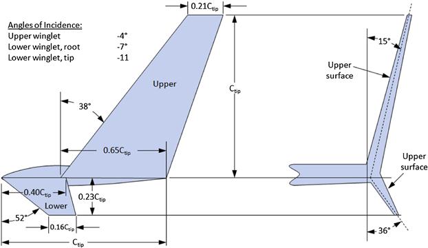
FIGURE 10-73 A general layout of the Whitcomb winglet (reproduced from Ref. [48]).
A flight test evaluation of a Whitcomb winglet on the McDonnell-Douglas DC-10 commercial jetliner in the early 1980s revealed that the most efficient configuration consisted of a combination of a slight aileron droop with a reduced span winglet. The combination reduced fuel burn at cruise by 3%, increased range by 2%, and reduced T-O distance by 5% at maximum gross weight [51]. In 1990, McDonnell-Douglas began deliveries of MD-11s with such a winglet installed. The winglet differed from the basic Whitcomb type in that it had a lower AR and started much closer to the leading edge of the wing (see Figure 10-74).
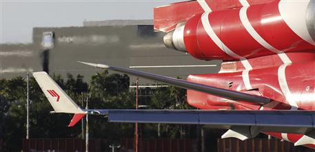
FIGURE 10-74 A Whitcomb winglet on a McDonnell-Douglas MD-11 commercial jetliner. (Photo by Phil Rademacher)
Reference [48] compared lift, drag, and pitching moment of a wind-tunnel model of the KC-135 with three wingtip devices attached: a wingtip extension of 38% of the height of the upper winglet, the upper winglet, and the upper and lower winglets combined. The results for drag are reproduced in Figure 10-75. It shows that the winglet generates less drag than simply extending the wingtip. It also shows that the drag reduction obtained by the upper and lower combination is no better than with only the upper winglet. This has resulted in a modification to the general Whitcomb design, to be discussed next. Strictly speaking, the smaller winglet does not have to be smaller – it is just so to prevent it from striking the ground on low-wing aircraft [48, p. 8].
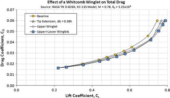
FIGURE 10-75 A drag polar comparing the basic KC-135 wing to one with a tip extension and Whitcomb winglet, one of which had the lower surface removed (reproduced from Ref. [48]).
The Blended Winglet
The blended winglet differs from the Whitcomb winglet in the absence of the lower winglet. As can be seen in Figure 10-75, the drag benefit of the Whitcomb winglet is marginal at low (cruise) lift coefficients to say the least. Comparing this contribution to the manufacturing complexity and weight, it is reasonable to simply remove it. Another difference between the two is the generous arc of the intersection between the wing and the winglet. This allows the wing airfoils to transition smoothly to the winglet airfoils. It also replaces the sharp intersection of the Whitcomb winglet, reducing the pressure peak and, therefore, local airspeeds. Keeping those low is important in preventing flow separation due to low-pressure peaks (interference drag) and the formation of normal shock at high Mach numbers (wave drag).
The blended winglet can be seen on many modern airliners. The most visible aircraft include aircraft such as the Boeing 737, Boeing 757 (see Figure 10-76), and many others.
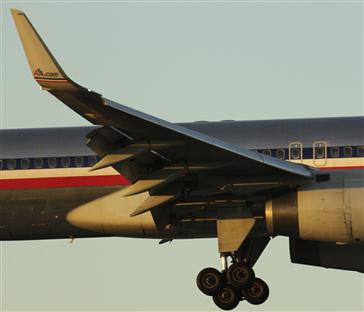
The blended winglet was designed and patented by Louis B. Gratzer as U.S. Patent 5,348,253. The patent states the theoretical background behind the design, where it is intended to solve a common deficiency of winglet installation – sharp discontinuities of intersections that result in departure from optimum loading. This is resolved using the gradual transition of the blended geometry, which allows the wingtip airfoil geometry to change smoothly to that of the winglet. It was specifically selected by Boeing due to fewer changes being required to the existing airframe [52]. Some pros and cons of winglets are presented in Table 10-7.

10.5.9 The Polyhedral Wing(tip)
The polyhedral wingtip is really a special wing shape and is also referred to as the cambered-span wing or non-planar wing (see Figure 10-77 and Figure 10-78). It consists of a gradually increasing dihedral at several wing stations along the wing. The idea originated with Cone [53], who showed that cambered-span wings can increase the effective AR by as much as 50% compared to a flat elliptical wing of equal span, producing equal lift. Cone [54] also presented a method and an illustrative example to help with the design of cambered-spans and evaluate the reduction in lift-induced drag. A good description of Cone’s highly theoretical work is presented by Jones [55].

FIGURE 10-77 Glaser-Dirks DG-1000 sailplane features a polyhedral wing. (Photo by Paul Hailday through Wikimedia Commons)

FIGURE 10-78 Comparison of the polyhedral wing, showing a straight wing, the polyhedral camber, and the ideal elliptical shape. (based on Ref. [56])
An incorporation of the polyhedral wing increases manufacturing complexity due to the break in the wing-spar and -skin. It also increases the dihedral effect. The polyhedral wingtip has been used on at least two sailplanes, the Schempp-Hirth Discus-2 and the Glaser-Dirks DG-1000 (see Figure 10-77).
From a conceptual design standpoint, non-planar wings can be considered from at least two perspectives, each of which leads to very different results. As explained below, it is very important to keep these results in mind when designing such aircraft. For a better understanding, refer to Figure 10-79.
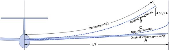
FIGURE 10-79 Comparison of a polyhedral wing to an actual wing flex. Wing A is the original straight wing of wingspan b and area S. Wing B is that same wing flexed due to airloads; it will suffer a reduction in its effective wing span and area. Wing C is a non-planar wing designed with wingspan b and S.
First, consider a stiff straight-wing design, denoted as Wing A in Figure 10-79. Assume that this wing has a baseline wingspan b, wing area S, and is generating some lift coefficient, CL. Then consider Wing B, which unloaded is geometrically identical to Wing A. However, assume that it is so flexible structurally that in level 1g flight the static aero-elastic effects deform it so forms the shape of Wing B. As can be seen in Figure 10-79, the resulting wingspan will be shortened by the amount Δb and its effective wing area will be reduced by an amount ΔS. Therefore, Wing b will have to be flown at a slightly higher AOA in order to generate the same lift coefficient as Wing a. For this reason, Wing b will generate higher lift-induced drag than Wing a. An example of such a scenario is shown in Figure 9-52, which compares the lift of a flexed and straight wing at the same AOA.
Alternatively, consider the non-planar Wing c in Figure 10-79. It is also designed with the same wingspan and wing area as Wing a, in addition to featuring the same planform shape. Assume this wing to be stiff, so, in contrast to Wing b, it does not flex in flight, but maintains its original span and area. This wing will generate the same lift coefficient as Wing a at a slightly lower AOA. Consequently, its lift-induced drag will be less.
This peculiar result can be attributed to a more efficient reduction of pressure on the upper surface due to the fact that the spanwise bound vortex is longer than that of the straight wing. This can be readily demonstrated using potential flow theory (e.g. vortex-lattice). Of course, Wing C has a greater wetted area than Wing A, it will be slightly heavier and this may offset the benefits some. A comparison between the three wing styles as a function of flex height is shown in Figure 10-80.
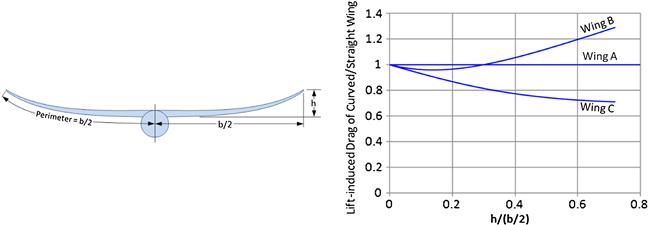
FIGURE 10-80 A comparison of the three wing styles discussed in this section. (based on Ref. [55])
10.5.10 Comparison Based on Potential Flow Theory
Potential flow theory can be used to evaluate the effectiveness of various wingtip devices, primarily when they are designed for operation at CL for which flow separation is still limited. This section compares a few such designs for lift, drag, and contribution to lateral stability (see Table 10-8). It can be used for guidance when selecting the appropriate wingtip geometry. Note that the table does not feature the winglet or the polyhedral wing.
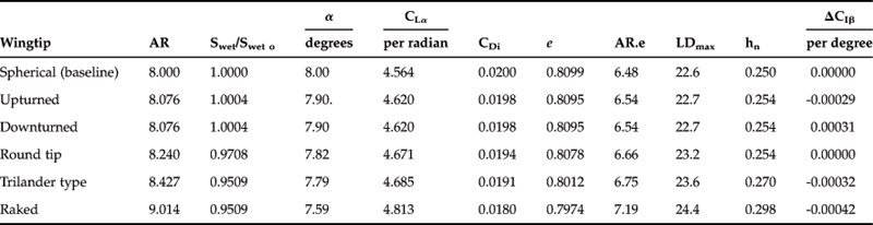
Of the wingtip types compared, it can be seen that the raked wingtip and the Trilander type yield the most efficient wings for cruising flight. Generally, the more efficient the wing style is, the steeper is its lift curve slope. The explanation for this can be seen in Figure 10-81, which shows that the section lift coefficients for the more efficient wing styles remain high along the tip. While favorable for cruise, this should also be kept in mind for stall characteristics. This means that the wingtip will be the first part of the wing to stall at higher AOAs. If the span of the wingtip is substantial, this can have a detrimental effect on the roll stability of the wing at stall. This would be less of a concern for a relatively short-span wingtip, such as the Trilander type, as it is subject to the formation of a leading edge vortex, similar to that of a deltawing. However, it may pose challenges for a long-span raked wingtip.


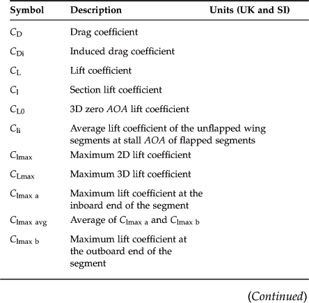
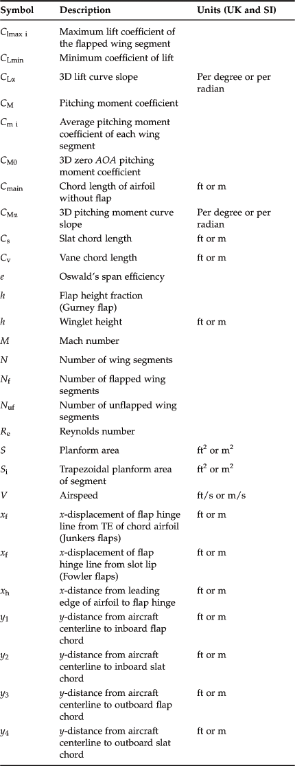

References
1. NACA TN-3007. Lift and Pitching Moment at Low Speeds of The NACA 64A010 Airfoil Section Equipped with Various Combinations of a Leading-Edge Slat, Leading-Edge Flap, Split Flap, and Double-Slotted Flap. Hayter: Nora-Lee F., and John A. Kelly; 1953.
2. NASA TM-4370. Variable-Camber Systems Integration and Operational Performance of the AFTI/F-111 Mission Adaptive Wing. Smith, John W., Wilton P. Lock, and Gordon A. Payne 1992.
3. NASA CR-158930. Assessment of Variable Camber for Application to Transport Aircraft 1980.
4. Smith AMO. High-Lift Aerodynamics. Journal of Aircraft. 1975;Vol. 12.
5. Liebeck RH, Smyth DN. Study of Slat-Airfoil Combinations Using Computer Graphics. Journal of Aircraft. 1973;Vol. 20.
6. NACA TR-407. The Characteristics of a Clark Y Wing Model Equipped with Several Forms of Low-Drag Fixed Slots. Weick: Fred E., and Carl J. Wenzinger; 1933.
7. Meier Hans-Ulrich. German Development of the Swept Wing 1935-1945. AIAA 2010.
8. NASA CR-4746. High-Lift System on Commercial Subsonic Airliners. Rudolph: Peter K. C; 1996.
9. NACA TM-1177. Wind-Tunnel Investigations on a Changed Mustang Profile with Nose Flap Force and Pressure-Distribution Measurements. Krüger: Werner; 1947.
10. NACA TN-71. Experiments with Slotted Wings. Lachmann: Gustav; 1921.
11. NACA TN-598. Wind Tunnel Tests of a Clark Y Wing with “Maxwell” Leading Edge Slots. Gauvain: William E; 1937.
12. NACA WR-L-574. Wind-Tunnel Investigation of an NACA 23012 Airfoil with an 18.05-Percent-Chord Maxwell Slat and with Trailing Edge Flap. Gillis: Clarence L., and John W. McKee; 1941.
13. NACA R-938. Summary of Section Data on Trailing-Edge High-Lift Devices. Cahill: Jones F; 1949.
14. Nayler, et al. Experiments on Models of Aeroplane Wings at the National Physical Laboratory. A.R.C. R.&M March 1914; No. 110.
15. Young AD. The Aerodynamic Characteristics of Flaps. R.&M. No. 2622, British A. R. C 1947.
16. Freedman Russell. The Wright Brothers: How They Invented the Airplane. Holiday House 1991;116.
17. NACA WR-L-373. Wind-Tunnel Investigation of Perforated Split Flaps for Use as Dive Brakes on a Tapered NACA 23012 Airfoil. Purser: Paul E., and Thomas R. Turner; 1941.
18. NACA TN-596. Full-Scale Wind-Tunnel and Flight Test of a Fairchild 22 Airplane Equipped with a Zap Flap and Zap Ailerons. Dearborn: C. H. and H. A. Soule; 1937.
19. NACA WR-L-437. Full-Scale Wind-Tunnel and Flight Tests of a Fairchild XR2K-1 Airplane with a Zap Flap and Upper-Surface Aileron-Wing Installation. O'Sullivan: William J; 1942.
20. NACA TN-524. Wind-tunnel Tests of a Wing with a Trailing-Edge Auxiliary Airfoil used as a Flap. Noyes: Richard W; 1935.
21. NACA R-541. Aerodynamic Characteristics of Wings with Cambered External Airfoil Flaps, Including Lateral Control, with a Full-Span Flap. Platt: Robert C; 1935.
22. Lott, Chabino Sarah. Guide to the Harlan D Fowler Papers 1920-1980 Collection number: MSS-1995-04. San José State University Library 2009.
23. NASA SP-2007-4409. The Wind and Beyond. Hansen: James R; 2007.
24. NASA CR-2443. Development of a Fowler Flap System for a High Performance General Aviation Airfoil. Wentz: W. H., Jr. and H. C. Seetharam; 1974.
25. NASA-CR-3687. Additional Flow Field Studies of the GA(W)-1 Airfoil with 30-percent Chord Fowler Flap Including Slot-Gap Variations and Cove Shape Modifications. Wentz: W. H., Jr. and C. Ostowari; 1983.
26. Liebeck Robert H. Design of Subsonic Airfoils for High Lift. Journal of Aircraft. September 1978;Vol. 15.
27. Cavanaugh Michael A, Robertson Paul, Mason William H. Wind Tunnel Test of Gurney Flaps and T-Strips on an NACA 23012 Wing. AIAA 2007-4175 2007.
28. Myose Roy, Papadakis Michael, Heron Ismael. Gurney Flap Experiments on Airfoils, Wings, and Reflection Plane Model. Journal of Aircraft. March–April 1998;Vol. 35.
29. NASA-TM-4071. A Water Tunnel Study of Gurney Flaps. Neuhart: Dan H., and Odis C. Pendergraft, Jr; 1988.
30. Vijgen Paul MH W, Howard Floyd G, Bushnell Dennis M, Holmes Bruce J. Serrated Trailing Edges for Improving Lift and Drag Characteristics of Lifting Surfaces. US-PATENT-5,088,665 1992.
31. Mayda EA, van Dam CP, Nakafuji D. Computational Investigation of Finite Width Microtabs for Aerodynamic Load Control. AIAA-2005-1185 2005.
32. TCDS A9EA. Viking Air Limited, Revision 15, 06/11/2012, FAA.
33. Hoerner Sighard F. Fluid-Dynamic Lift. L. Hoerner 1965; 3–6.
34. Hoerner Sighard. Aerodynamic Shape of the Wing Tips. Technical Report 5752, USAF, Air Material Command, Wright-Patterson Air Force Base 1949.
35. Hoerner Sighard F. Fluid-Dynamic Drag. L. Hoerner 1965.
36. NASA TM-88534. The Aerodynamic Optimization of Wings at Subsonic Speeds and the Influence of Wingtip Design. Zimmer H 1987; Dissertation 1983.
37. Rokhsaz Kamran. A Brief Survey of Wing Tip Devices for Drag Reduction. SAE. 1993;932574.
38. Naik DA, Ostowari C. Effects of Nonplanar Outboard Wing Forms on a Wing. Journal of Aircraft. 1990;Vol. 27:117–122.
39. NACA TN-69. An Investigation on the Effect of Raked Wing Tips. Norton: F. H.; 1921.
40. Diaz Mario R Avila, Yechout Thomas R, Bryant Elaine M. ‘The Rakelet’ - A Wingtip Modification Approach to Improve Endurance. Range and Fuel Savings, AIAA 2012-0669 2012.
41. NACA TR-201. The Effects of Shielding the Tips of Airfoils. Reid: Elliott G; 1925.
42. NACA TN-2440. Wind-Tunnel Investigation and Analysis of the Effects of End Plates on the Aerodynamic Characteristics of an Unswept Wing. Riley: Donald R; 1951.
43. NACA TM-856. The Lift Distribution of Wings with End Plates. Mangler: W; 1938.
44. NACA R-267. Drag of Wings with Endplates. Hemke: Paul E; 1927.
45. Weber J. Theoretical Load Distribution on a Wing with Vertical Plates. A.R.C R.&M No. March 1956;2960.
46. McCormick Barnes W. Aerodynamics, Aeronautics, and Flight Mechanics. John Wiley & Sons 1979.
47. NASA SP-2003-4529. Concept to Reality. Chambers: Joseph R.; 2003.
48. NASA TN D-8260. A Design Approach and Selected Wind-Tunnel Results at High Subsonic Speeds for Wing-Tip Mounted Winglets. Whitcomb: Richard T; 1976.
49. NASA TN D-8264. A High Subsonic Speed Wind Tunnel Investigation of Winglets on a Representative Second-Generation Jet Transport Wing. Whitcomb: Richard T., S. G. Flechner, and P. F. Jacobs; 1976.
50. NASA SP-4303. On the Frontier - Flight Research at Dryden, 1946-1981. Hallion: Richard P., NASA History Series; 1984.
51. NASA CR-3748. DC-10 Winglet Flight Evaluation – Summary Report. Taylor: A. B.; 1983.
52. Anonymous. Blended Winglets for Improved Airplane Performance. Boeing Publication.
53. NASA TR-R-139. The Theory of Induced Lift and Minimum Induced Drag of Nonplanar Lifting Systems. Cone: Clarence D. Jr; 1962.
54. NASA TR-R-152. The Aerodynamic Design of Wings with Cambered Span having Minimum Induced Drag. Cone: Clarence D. Jr; 1960.
55. Jones Robert T. Minimizing Induced Drag. Soaring and Motorgliding. October 1979;Vol. 43.
56. Thomas Fred. Fundamentals of Sailplane Design. College Park Press 1999.
57. Barnes Chris H. Handley Page Aircraft since 1907, Putnam, 1976.
1This assumes a gross weight of 2920 lbf, wing area of 280 ft2, and stalling speed of 27 KCAS.
2The purpose of which is to help prevent shock formation between the upper surface of the wing and the fuselage.
3An article on Wikipedia states the design was so successful that licensing fees to other companies are acclaimed as its main source of income in the early 1920s. This claim has not been verified and the author is reluctant to take it at face value. However, it is presented here as an anecdote, as it is interesting if true.