Day 29. EtherChannel Concepts and Configuration
CCNA 200-101 ICND2 Exam Topics
![]() Identify enhanced switching technologies
Identify enhanced switching technologies
![]() Troubleshoot EtherChannel problems
Troubleshoot EtherChannel problems
Key Topics
EtherChannel technology allows you to bundle multiple physical interfaces into one logical channel to increase the bandwidth on point-to-point links. In addition, EtherChannel provides a way to prevent Spanning Tree Protocol (STP) convergence from being needed when only a single port or cable failure occurs. Today, you review EtherChannel concepts and configuration.
EtherChannel Operation
EtherChannel, a technology originally developed by Cisco, can bundle up to eight equal-speed links between two switches, as shown between the two distribution layer switches in Figure 29-1.

STP sees the bundle of links as a single interface. As a result, if at least one of the links is up, STP convergence does not have to occur. This makes much better use of available bandwidth while reducing the number of times STP must converge. Without EtherChannel, STP would block all the links except one.
Benefits of EtherChannel
When an EtherChannel is configured, the resulting virtual interface is called a port channel. The physical interfaces are bundled together into a port channel interface. EtherChannel has the following benefits:
![]() Most configuration tasks can be done on the EtherChannel interface instead of on each individual port, thus ensuring configuration consistency throughout the links.
Most configuration tasks can be done on the EtherChannel interface instead of on each individual port, thus ensuring configuration consistency throughout the links.
![]() It relies on the existing switch ports to increase bandwidth. No hardware upgrades are needed.
It relies on the existing switch ports to increase bandwidth. No hardware upgrades are needed.
![]() Load balancing is possible between links that are part of the same EtherChannel. (Load-balancing configuration is beyond the scope of the CCNA exam.)
Load balancing is possible between links that are part of the same EtherChannel. (Load-balancing configuration is beyond the scope of the CCNA exam.)
![]() EtherChannel creates an aggregation that is recognized by STP as one logical link.
EtherChannel creates an aggregation that is recognized by STP as one logical link.
![]() EtherChannel provides redundancy. The loss of one physical link does not create a change in the topology.
EtherChannel provides redundancy. The loss of one physical link does not create a change in the topology.
Implementation Restrictions
Keep in mind a few limitations when implementing EtherChannel:
![]() Interface types, like Fast Ethernet and Gigabit Ethernet, cannot be mixed within the same EtherChannel.
Interface types, like Fast Ethernet and Gigabit Ethernet, cannot be mixed within the same EtherChannel.
![]() Cisco IOS Software currently only supports up to six EtherChannels.
Cisco IOS Software currently only supports up to six EtherChannels.
![]() Some servers also support EtherChannel to the switch to increase bandwidth; however, the server would need at least two EtherChannels to provide redundancy because it can send traffic to only one switch through the EtherChannel.
Some servers also support EtherChannel to the switch to increase bandwidth; however, the server would need at least two EtherChannels to provide redundancy because it can send traffic to only one switch through the EtherChannel.
![]() The EtherChannel configuration must be consistent on both switches. The trunking configuration (native VLAN, allowed VLANs, and so on) must be the same. And all ports must be Layer 2 ports.
The EtherChannel configuration must be consistent on both switches. The trunking configuration (native VLAN, allowed VLANs, and so on) must be the same. And all ports must be Layer 2 ports.
![]() All ports in the EtherChannel must be Layer 2 ports, or all ports within the EtherChannel must be Layer 3 ports.
All ports in the EtherChannel must be Layer 2 ports, or all ports within the EtherChannel must be Layer 3 ports.
Note
You can configure Layer 3 EtherChannels on multilayer switches; however, that is beyond the scope of the CCNA exam.
EtherChannel Protocols
You can configure EtherChannel as static or unconditional; however, there are also two protocols that can be used to configure the negotiation process: Port Aggregation Protocol (PAgP—Cisco proprietary) and Link Aggregation Control Protocol (LACP—IEEE 802.3ad). These two protocols ensure that both sides of the link have compatible configurations—same speed, duplex setting, and VLAN information. The modes for each differ slightly.
Port Aggregation Protocol
PAgP is a Cisco proprietary protocol that aids in the automatic creation of EtherChannel links. PAgP checks for configuration consistency and manages link additions and failures between two switches. It ensures that when an EtherChannel is created, all ports have the same type of configuration. PAgP uses the following modes:
![]() On: This mode forces the interface to channel without PAgP.
On: This mode forces the interface to channel without PAgP.
![]() Desirable: The interface initiates negotiations with other interfaces by sending PAgP packets.
Desirable: The interface initiates negotiations with other interfaces by sending PAgP packets.
![]() Auto: The interface responds to the PAgP packets that it receives but does not initiate PAgP negotiation.
Auto: The interface responds to the PAgP packets that it receives but does not initiate PAgP negotiation.
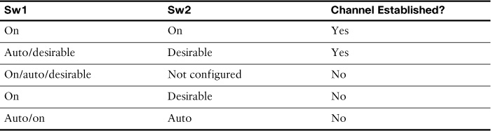
The modes must be compatible on each side of the EtherChannel. For example, Sw1 and Sw2 in Figure 29-2 must be configured with one of the combinations of settings shown in Table 29-1.

Link Aggregation Control Protocol
Link Aggregation Control Protocol (LACP) is part of an IEEE specification (802.3ad) that allows a switch to negotiate an automatic bundle by sending LACP packets to the peer. It performs a function similar to PAgP with Cisco EtherChannel. Cisco devices support both PAgP and LACP. LACP uses the following modes:
![]() On: This mode forces the interface to channel without LACP.
On: This mode forces the interface to channel without LACP.
![]() Active: The interface initiates negotiations with other interfaces by sending LACP packets.
Active: The interface initiates negotiations with other interfaces by sending LACP packets.
![]() Passive: The interface responds to the LACP packets that it receives but does not initiate LACP negotiation.
Passive: The interface responds to the LACP packets that it receives but does not initiate LACP negotiation.
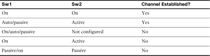
Like PAgP, the LACP modes must be compatible on each side of the EtherChannel. For example, Sw1 and Sw2 in Figure 29-2 must be configured with one of the combinations of settings shown in Table 29-2.
Note
For both protocols, the on mode creates the EtherChannel configuration unconditionally, without PAgP or LACP dynamic negotiation. You should probably memorize the mode settings for both PAgP and LACP in preparation for the CCNA exam.
Configuring EtherChannel
To implement EtherChannel, follow these steps:
Step 1 Specify the interfaces that you want to bundle together in one link using the interface range interfaces command.
Step 2 Create a port channel using the channel-group identifier mode mode command. The identifier can be any number between 1 and 6, inclusive, and does not have to match the other switch. The mode will be either on or one of the PAgP or LACP modes.
Step 3 Enter interface configuration mode for the new port channel with the interface port-channel identifier command. The identifier is the same number used in the channel-group command.
Step 4 Configure the trunking and VLAN settings.
Using the topology in Figure 29-2, assume that Sw1 is already configured for EtherChannel with F0/1 and F0/2 trunking. The native VLAN is 86. The allowed VLANs are 1, 10, 20, and 86. EtherChannel is forced on. No PAgP or LACP is needed. Example 29-1 shows the configuration for Sw2.
Example 29-1 EtherChannel Configuration
Sw2(config)# interface range f0/1-2
Sw2(config-if-range)# channel-group 1 mode on
Creating a port-channel interface Port-channel 1
Sw2(config-if-range)# interface port-channel 1
Sw2(config-if)# switchport mode trunk
Sw2(config-if)# switchport trunk native vlan 86
Sw2(config-if)# switchport trunk allowed vlan 1,10,20,86
If configuring PAgP or LACP, use the appropriate mode keyword for the channel-group command. Just ensure that the commands on both sides of the channel are compatible according to Tables 29-1 and 29-2.
Verifying EtherChannel
If you configured management addressing, you can quickly verify both sides of an EtherChannel bundle by pinging across the trunk. The two switches should be able to ping each other. Also, devices configured as members of the various VLANs should be able to ping each other.
To verify the configuration, use the show run command, as shown in Example 29-2.
Example 29-2 Verifying the EtherChannel Configuration
Sw2# show run | begin interface Port
interface Port-channel1
switchport trunk native vlan 86
switchport trunk allowed vlan 1,10,20,86
switchport mode trunk
!
interface FastEthernet0/1
switchport trunk native vlan 86
switchport trunk allowed vlan 1,10,20,86
switchport mode trunk
channel-group 1 mode on
!
interface FastEthernet0/2
switchport trunk native vlan 86
switchport trunk allowed vlan 1,10,20,86
switchport mode trunk
channel-group 1 mode on
To get an overall summary of the EtherChannel configuration, use the show etherchannel summary command, as shown in Example 29-3.
Example 29-3 Verifying EtherChannel Is Operational
Sw2# show etherchannel summary
Flags: D - down P - bundled in port-channel
I - stand-alone s - suspended
H - Hot-standby (LACP only)
R - Layer3 S - Layer2
U - in use f - failed to allocate aggregator
M - not in use, minimum links not met
u - unsuitable for bundling
w - waiting to be aggregated
d - default port
Number of channel-groups in use: 1
Number of aggregators: 1
Group Port-channel Protocol Ports
------+-------------+-----------+-----------------------------------------------
1 Po1(SU) - Fa0/1(P) Fa0/2(P)
To verify the operational status of a specific interface in the EtherChannel bundle, use the show interface switchport command, as shown in Example 29-4.
Example 29-4 Verifying an Interface’s Port Channel Settings
Sw2# show interface fa0/1 switchport
Name: Fa0/1
Switchport: Enabled
Administrative Mode: trunk
Operational Mode: trunk (member of bundle Po1)
Administrative Trunking Encapsulation: dot1q
Operational Trunking Encapsulation: dot1q
Negotiation of Trunking: On
Access Mode VLAN: 1 (default)
Trunking Native Mode VLAN: 86 (VLAN0086)
Administrative Native VLAN tagging: enabled
Voice VLAN: none
Administrative private-vlan host-association: none
Administrative private-vlan mapping: none
Administrative private-vlan trunk native VLAN: none
Administrative private-vlan trunk Native VLAN tagging: enabled
Administrative private-vlan trunk encapsulation: dot1q
Administrative private-vlan trunk normal VLANs: none
Administrative private-vlan trunk associations: none
Administrative private-vlan trunk mappings: none
Operational private-vlan: none
Trunking VLANs Enabled: 1,10,20,86
Pruning VLANs Enabled: 2-1001
Study Resources
For today’s exam topics, refer to the following resources for more study.
