
Visual Basic for Applications (VBA) is a programming language and environment that is included with many Microsoft applications, such as Word, Excel, PowerPoint, and Access. Since Release 14, VBA has been available with AutoCAD as well. VBA is ideally suited for situations in which you need to work with more than one application at a time. ActiveX, which I discussed in the last chapter in relation to Visual LISP, enables you to access objects in other applications. However, you can also use VBA to program AutoCAD alone. This chapter introduces you to VBA and shows how you can start to use this powerful language to customize AutoCAD.
Note
AutoCAD LT does not support VBA. This entire chapter applies to AutoCAD only.
Visual Basic for Applications is a variation of Visual Basic. Visual Basic is not related to any specific application. Visual Basic code is compiled into an executable file that stands alone, unrelated to any specific document. VBA, on the other hand, is connected to its application and the document in which you created the code. VBA provides a simple way to customize AutoCAD, automate tasks, and create programs from within the application.
VBA in AutoCAD works slightly differently from VBA in most other applications, in that VBA projects are stored in a separate file, with the DVB filename extension, but can also be stored within the drawing file.
Note
By default, VBA is not installed with AutoCAD 2010. To load and run VBA projects from a previous release, you need to download and install the VBA module from www.autodesk.com/vba-download. On the Web site, choose the correct file based on your operating system. When installed, VBA related commands and functions work normally. The reason for this change is due to Autodesk's transition from VBA to VSTA and .NET.
After you decide to program AutoCAD, the first step is to select a programming language to use.
VBA has the following advantages:
VBA is faster than AutoLISP, even when AutoLISP is compiled.
VBA is common to many other applications. If you've used VBA before, you can easily transfer your knowledge to using VBA in AutoCAD. You're also more likely to find other programmers who know VBA, compared to AutoLISP.
VBA is generally easier to learn than AutoLISP because of its syntax.
On the other hand, AutoLISP has the advantage of backward compatibility with prior releases of AutoCAD. Of course, if you're familiar with AutoLISP but not with VBA, it's hard to beat the ease of working with a language that you already know and use.
VBA programs are saved in projects. A project contains all the parts that are needed to execute the function of the program. You can use the VBA Manager to view your VBA projects. The VBA Manager also enables you to load, unload, save, and create VBA projects. To open the VBA Manager, choose Manage tab
VBA projects can contain modules. A module is a self-contained piece of programming code. A VBA project can have one or more modules.
To add a module, choose Insert
Tip
You can resize the module text editor as you would any window. As you start adding code to the text editor, you'll find it easier to work with a larger area. Click the Maximize button to enlarge the text editor to its maximum size.
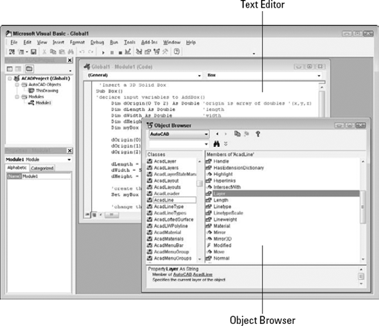
To see the list of AutoCAD objects, click the <All Libraries> drop-down list and choose AutoCAD. You can see the result in Figure 37.1.
Tip
You can resize the panes in the Object Browser. Place the mouse cursor on the bar between the panes until you see the double-headed arrow, and drag it either left or right.
In the left pane, labeled Classes, you see the list of objects. In VBA, you can have both individual objects and collections of objects. For example, AcadLayer would be the layer object, and AcadLayers would be the collection of layers. The purpose of collections is to enable you to work with a group of similar objects. For example, to add a layer, you add it to the collection of layers for the current drawing; this is because the new layer is not related to any existing layer.
What can you do with objects in VBA? First, objects can have properties. For example, you can set an ellipse to the color red because one of the properties of the ellipse object is TrueColor. (Of course, all drawing objects have TrueColor as one of their properties.)
Second, objects have methods. A method is an action that you can take on the object. For example, you can delete (erase) an ellipse because Delete is a method of the ellipse object (as well as of all drawing objects).
In the Object Browser, the right pane, Members, lists the properties and methods of any object that you choose in the Classes pane.
Although you might first think that an object in VBA is the same as an object in an AutoCAD drawing, there is more to the story. In VBA, everything is an object. For example, AutoCAD as an application is an object. Your current drawing is also an object. Model space and paper space are also objects. Therefore, to specify an object in your drawing, you need to specify the application, the drawing, and finally the object in the drawing. To do this, VBA works with a hierarchy of objects. For example, the hierarchy makes it possible to distinguish between an object in your drawing and an object in an Excel spreadsheet.
Objects are specified from the most general to the most specific, with a period between each part of the definition. You then add the desired method or properties after another period. For example, you can use the following VBA code to add a circle:
Application.ActiveDocument.ModelSpace.AddCircle(center, radius)
A shortcut for Application.ActiveDocument is ThisDrawing, so you can also use:
ThisDrawing.ModelSpace.AddCircle(center, radius)
In order to work with any object, you need to know where it fits in the hierarchy. The quickest way to see the hierarchical structure from the VBA IDE is to choose any method or property in the Object Browser and to choose the Help (question mark) button on the Object Browser's toolbar. On the Contents tab, choose Object Model to see the listing in Figure 37.2.
Note
Within AutoCAD, choose InfoCenter toolbar
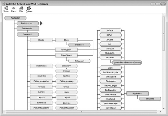
Figure 37.2. The object model shows you the hierarchy of all the VBA objects so that you can work with them.
STEPS: Becoming Acquainted with the VBA Environment

Choose Insert

Move down to the Windows task bar and click the AutoCAD button to return to AutoCAD. Now click the Microsoft Visual Basic button to return to the VBA IDE.

In the Classes pane, click AcadLine. You see the associated properties and methods in the right pane.
In the right pane, which is labeled Members of AcadLine, click Delete. You see the following at the bottom of the window:
Sub Delete()
    Member of AutoCAD.AcadLine
    Deletes a specified object
Note
The description text of the selected method, property, or class does not appear at the bottom of the Object Browser in a 64-bit version of AutoCAD, but you do see the member to which it is related.
Subindicates the start of a VBA subroutine. Methods are listed in this way.In the right pane, click Layer. At the bottom of the window, you see the following:
Property Layer As String
    Member of AutoCAD.AcadLine
    Specifies the current layer of the object
This indicates that
Layeris a property of AcadLine.Stringrefers to the data type, discussed later in this chapter.Click the Help (question mark) button in the Object Browser. You see the Help page for the
Layerproperty.On the Contents tab, double-click Objects and then click Line object. Scroll down to see all the properties and methods that belong to the Line object.
In the second paragraph of the description, the word AddLine is underlined with a hypertext line. Click it to see the description of the
AddLinemethod.At the top of the page, click Example (also with a hypertext underline). You see an example of VBA code for creating a line.
Close Help by clicking the Close button at the top-right corner of each window. Leave the VBA IDE window open if you're continuing on to the next exercise.
VBA offers several help features. You've already seen the Object Browser, which provides you with a list of objects as well as their properties and methods. To access help on an object, choose it in Object Browser and click Help. You can do the same for a method or property, as shown in Figure 37.3.
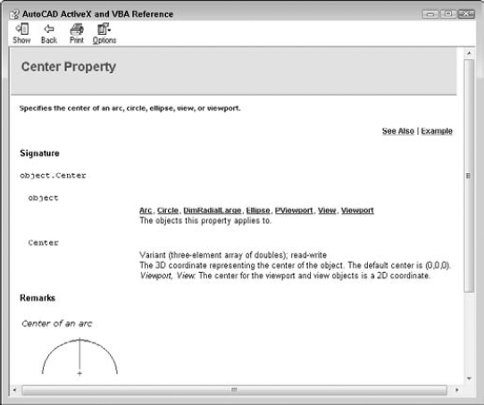
After you open a help page, click Example to see an example. These examples are a great way to learn VBA. You can copy a snippet of VBA code and paste it into your own routine, and then edit it as you want.
For more general help, AutoCAD offers two systems:
The ActiveX and VBA Reference is an alphabetical listing of objects, methods, properties, and events.
The ActiveX and VBA Developer's Guide explains ActiveX automation concepts and techniques.
To access these reference guides, switch to AutoCAD and click the Help button or press F1. Then click the Contents tab and choose ActiveX Automation and VBA.
The Microsoft Visual Basic for Applications Help provides information on the general VBA environment. Click Help on the VBA IDE Menu Bar toolbar. Here you see help for other VBA-enabled applications that you may have. You can use this when you're ready to write VBA code that integrates more than one application.
After you start programming, you can get help on any class, method, or property by clicking it and pressing F1. For example, you can type AddLine and press F1 to access help on how to create a line.
Now that you're familiar with the structure of VBA objects, methods, and properties, you're ready to start writing some code. As with any programming language, you need to learn syntax and understand variables and when to use them. Luckily, AutoCAD's VBA Help includes many examples to guide you along the way. After you write some code, you can use it in AutoCAD.
Table 37.1 lists the various components of VBA code. This table defines various terms that you can often use when working with VBA.
Table 37.1. Components of VBA Code
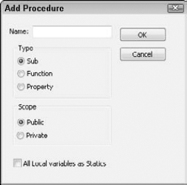
When you start to create code, VBA can create the basic structure for each procedure for you. With the text editor for a module displayed, choose Insert
In the Name text box, type in a name for the new procedure, and then choose the type of procedure that you want to create. Choose whether you want the scope to be Public or Private and then click OK. If a subroutine (called sub for short) is declared Public, it is visible (can be called) from other modules or from the Macros dialog box in AutoCAD. A sub that is declared Private is visible only within that module.
Note
If you check the All Local Variables as Statics check box in the Add Procedure dialog box, your variables retain their values between the times that they're used.
To start programming, you need an idea of how a VBA procedure is put together. Here is a complete VBA subroutine that draws a 3D solid box.
'Insert a 3D Solid Box
Sub Box()
'declare input variables to AddBox()
     Dim dOrigin(0 To 2) As Double 'origin is array of doubles '(x,y,z)
     Dim dLength As Double         'length
     Dim dWidth As Double          'width
     Dim dHeight As Double         'height
     Dim myBox As Acad3DSolid      'holds return from AddBox()

     dOrigin(0) = 0#               'set origin to (0,0,0)
     dOrigin(1) = 0#
     dOrigin(2) = 0#
dLength = 5# 'make a cube 5 by 5 by 5
dWidth = 5#
dHeight = 5#
'create the box in modelspace of the current drawing
Set myBox = ThisDrawing.ModelSpace.AddBox(dOrigin, dLength, _
dWidth, dHeight)
'change the viewpoint to better see the box
ThisDrawing.SendCommand ("VPOINT 1,1,1 ")
End SubLine 1. Any text starting with an apostrophe (
') is a comment. Placing comments in your modules helps you and others to understand what you're doing.Line 2.
Subindicates the start of a procedure, which is a named, unified piece of code. You can have several subroutines in a VBA project. A project is the file that you save, and it has a DVB file extension. Each project contains the components of your subroutines, dialog boxes, and so on. The next word is the name of the subroutine. Within the parentheses, you can add arguments, if any. Use an empty set of parentheses if there are no arguments. Declaring variables is discussed later in this chapter.Line 3. Another comment describing the next few lines of code. It's always a good idea to comment your code, indicating what is happening and reminding yourself of your intent.
Line 4. You declare variables by using the
Dimstatement. HeredOriginis used as the variable for the center of the box.(0 To 2)means that the origin will have three parts to it, for the X, Y, and Z coordinates.Doubleis a type of variable that is suitable for most coordinates. More about variable types later.Lines 5–7. Here you declare the
dLength,dWidth, anddHeightvariables, which will be used as the length, width, and height of the box. These are declared as typeDouble, which is also indicated by thedprefix on the variable names. This isn't required, but it's a good idea to use a naming scheme for variables to help remind you of their type, especially as you get deeper into programming or have to come back to some code after not seeing it for a while.Line 8. Here you declare a variable called
myBoxas anAcad3DSolidto refer to the new box that will be created.Acad3DSolidis a data type that is specific to AutoCAD, and suitable for (you guessed it) referencing a 3D solid in your drawing. You can find other AutoCAD data types by looking in the Object Browser, or by looking at the Object Model, as I explained earlier in this chapter.Lines 9–11. Here you specify the X, Y, and Z coordinates of the origin of the box. The values are assigned to the
dOriginvariable. The pound sign (#) is used to indicate a double-precision floating-point value. Use of the#sign is not required here but is more accurate and more clearly indicates your intentions. In some situations, rounding errors can occur when assigning numbers of one type to variables of another type, such as when you assign integers to doubles and doubles to integers.Lines 12–14. Set the length, width, and height of the box to 5.
Line 15. Another comment.
Line 16. Finally, you're ready to actually do something. The
Setstatement is used to set a variable to an object. Here you set the variablemyBoxto anAcad3DSoliddefined by theAddBoxmethod. TheAddBoxmethod creates a new 3D box. You need to define its origin, length, width, and height by using the variables that you've previously defined. TheAddBoxmethod is a member ofModelSpace, which is a member ofThisDrawing. You useThisDrawingin VBA to access the current drawing. Because VBA within AutoCAD is automatically connected to AutoCAD, you don't need to specify the application (that is, AutoCAD).Line 17. Is a continuation of the parameters used for the
AddBoxmethod. The _ (underscore) at the end of Line 16 indicates that the line of code extends to the next line. Using the underscore allows you to keep your code lines shorter to reduce scrolling.Line 18. Not another comment! Ask yourself these questions: If I looked at this code without the comments, would I have a harder time understanding it? What if there is a bug and I ask another programmer to find it? What if I am that programmer?
Line 19. Here you send the VPOINT command to change the viewpoint. Otherwise, the box that you just created will simply look like a square viewed from the top. The space after the numbers 1,1,1 and before the quotation mark is important; it signifies the end of the command. It's like pressing the Enter key for this command.
Line 20.
End Subends the subroutine.
To find the syntax for a statement that you want to use, look in VBA Help, as explained in the "Accessing help" section earlier in this chapter. In the preceding VBA routine, you might want to click AddBox and press F1 to find the syntax and elements that are required for creating a box. Then click Example to see an actual example of code for that statement.
As I mention earlier, the AutoCAD version of VBA saves VBA projects as separate files with a DVB file extension. However, when you run a routine, AutoCAD lists it in the format ModuleName:Procedure Name. If your project has only one module, you can give the module and the procedure the same name. However, most VBA routines have more than one module, with one module controlling the rest. By running the controlling module, you run the whole project.
To name a module, look in the Properties window. After you've created a module, the VBA IDE lists its name property as Module1 by default. Double-click Module1 and type a new name. Notice that the module name in the Project window also changes accordingly.
Note
A module name (as well as the names of other forms and controls) must start with a letter and can be up to 31 characters. Only letters, numbers, and the underscore character are allowed.
You can save your project in the SampleVBA subfolder in the AutoCAD 2010 folder, or use another folder that is in the support-file search paths of AutoCAD.
When you type code from scratch in the Visual Basic editor, you immediately notice that Visual Basic color-codes your text as you go. The most common colors are:
Normal text | Black |
Syntax-error text | Red |
Comments | Green |
Keyword text | Blue |
Keywords include variable types and other words that Visual Basic recognizes, such as Dim and Sub.
Tip
You can customize these colors by choosing Tools
When you start to type a keyword that Visual Basic recognizes, you'll often see a box pop up that enables you to choose from a list, or that helps you to complete the word. The editor also adds or removes spaces and capitalizes certain words for you to improve your syntax. If you make a syntax mistake, a small error message often appears as you work. In these ways, the Visual Basic editor helps you to type accurate code.
STEPS: Creating, Saving, and Running a VBA Program

Choose Insert
Choose Insert
Type the following code. (Note that the second and last lines are already there for you.)
'insert a Torus
Public Sub DrawTorus()
    'declare variables
    Dim dCenter(0 To 2) As Double
    Dim dRadius1 As Double
    Dim dRadius2 As Double
    Dim myTorus As Acad3DSolid

    'set center of torus to 0,0,0
    dCenter(0) = 0#: dCenter(1) = 0#: dCenter(2) = 0#
    dRadius1 = 10#      'torus radius
    dRadius2 = 2#       'tube radius

    'insert the torus
    Set myTorus = ThisDrawing.ModelSpace.AddTorus(dCenter,_
                  dRadius1)

    'set the viewpoint and shade it
    ThisDrawing.SendCommand (VPOINT 1,1,1 VSCURRENT CONCEPTUAL)
End Sub
In the Properties window, change the name of the module to DrawTorus.


Don't save your drawing.
Here's an explanation of the routine that you just wrote and used. Note that blank lines are ignored.
Line 1. Comment describing routine.
Line 2. This is a public subroutine named DrawTorus with no parameters.
Line 3. Comment indicating which variable declarations are next.
Line 4. Declare the array to hold the X, Y, and Z coordinates for the center of the torus.
Line 5. Declare the variable to hold the radius of the torus.
Line 6. Declare the variable to hold the radius of the tube.
Line 7. Declare the variable to hold the created 3D object.
Line 8. Comment.
Line 9. Set the center to 0,0,0.
Line 10. Set the torus radius to 10.0.
Line 11. Set the tube radius to 2.0.
Line 12. Comment.
Line 15. Comment.
Line 16. Send commands to AutoCAD to set the viewpoint and set the visual style to Conceptual for better viewing.
Line 17. End of subroutine.
A variable holds a value for later use in your program. In VBA, you don't need to explicitly declare your variables in advance (as long as you don't include Option Explicit, which I explain later). You use the Set statement to set a variable to an object, as in the example here. This statement creates a variable, cir, and sets its value equal to the circle that the AddCircle method creates.
Set cir = ThisDrawing.ModelSpace.AddCircle(cen, radius)
When you create a variable in this way, VBA assigns the default variant type to it. The variant type of variable can contain numbers, dates, or strings (of text).
However, declaring variables explicitly in advance has two advantages:
You can specify the type of variable, which usually uses less memory than the default variant type.
As you continue to enter code, VBA checks the variable's spelling for you, thus reducing the chance for errors.
You declare variables by using the Dim statement. Here's an example:
Dim radius As Double
You can create three different levels of variables:
A
Publicvariable is available to all the procedures in the project. It is shown as follows:Public dRadius As Double
A module-level variable is available to all the procedures in the module. You create a module-level variable by placing the declaration (with the
Dimstatement) at the top of a module, in a Declarations section. Another way to create a module-level variable is to use thePrivatestatement. Examples are shown here:Dim dNum3 as Double Private dNum2 as Double
A procedure-level variable is used only within a procedure. You can place the variable anywhere within the procedure, as long as you declare the variable before you use it.
Placing the statement Option Explicit in a Declarations section requires all variables to be declared. Using Option Explicit is a way to force yourself to write your code more carefully. Declared variables are easier to debug because they're easier to find.
Table 37.2 describes the kinds of variables that you can declare.
Table 37.2. VBA Variable Types
Here's an example that uses the Date variable type and displays it in a message box:
Sub DateDemo()
Dim dt As Date
Dim dbl As Double
    dt = Now        'set the dt to the current date and time
    dbl = dt        'assign this date value to a double
MsgBox "Normal date version: " & dt & "  Double version: " & dbl
End Sub
Running DateDemo (by pressing F5) would show something similar to:
Normal date version: 5/10/2005 8:03:13 PM
Double version: 38482.8355671296
Although a complete discussion of how to write VBA code is beyond the scope of this book, some general principles will be helpful.
A statement in VBA is the most basic unit of code. It contains a complete instruction. There are three kinds of statements:
A declaration names a variable, constant, or procedure, as in this example:
Dim dOrigin as Double
An assignment assigns a value to a variable or constant. For example:
dOrigin = 0#
An executable creates an action. For example, it can execute a method or function, or create a loop or branch that acts on a block of code, as shown here:
Set myLine = ThisDrawing.ModelSpace.AddLine(dStartPt, dEndPt)
VBA has many keywords, functions, and other components that you can use to create code. To find the basic components of the VBA language, choose Help
Constants. Constants can be used anywhere in your code to provide a named value. For example, VBA offers color and date constants that you can use to specify colors and dates.
Functions. VBA includes many functions that you'll find familiar if you've used AutoLISP. For example, the ABS function returns the absolute value (without a plus or minus sign) of any number. The DATE function returns the current system date.
Keywords. Keywords are words that have a special meaning in VBA. They are often used as parts of VBA statements. For example,
Elseis a keyword that is used in theIf...Then...Elsestatement. You're already familiar with theSetkeyword, which is used in theSetstatement.Operators. VBA includes all the usual arithmetic operations, such as
+,−,*,/, and^. You can also use&to concatenate text strings. There are several logical operators, such asand,not, andor.Statements. Statements help you to create the flow of your code. You're already familiar with the
Setstatement. Other statements areFor Each...NextandIf...Then...Else. These provide looping capabilities in VBA.
Remember that you can also find a list of objects and their properties and methods in the Object Browser, as I explained earlier in this chapter.
The examples shown in this chapter weren't very useful, partly because the routines provided no way to get user input for the properties of the objects that they drew. There are two main ways to get user input: on the command line and through a dialog box. In this section, I explain how to get user input on the command line.
In order to use the user-input methods, you need to first use something called the Utility object. The Utility object belongs to the Document object and controls the methods that get user input. You can also use ThisDrawing, as in the following example:
Dim iReturn as Integer
iReturn = ThisDrawing.Utility.GetInteger("Enter an integer: ")
Here you set a variable called iReturn that is equal to the integer that the user types on the command line. The prompt is Enter an integer:.
You can use this type of user input to get a pick point, a numeric value (such as the radius of a circle), a text string, or an object. Use this method when the input is short and sweet.
To avoid several prompts appearing on the same line, use vbCrLf, the carriage return/linefeed constant, at the beginning of a prompt, as in the following example:
prompt1 = vbCrLf & "Specify center point: "
Here's an example that illustrates how to get user input on the command line:
Sub AddCircle()
    Dim vPt As Variant
    Dim dRadius As Double
    Dim myCircle As AcadCircle

    vPt = ThisDrawing.Utility.GetPoint(, vbCrLf & "Enter Center Point: ")
    dRadius = ThisDrawing.Utility.GetReal(vbCrLf & "Enter radius: ")
    Set myCircle = ThisDrawing.ModelSpace.AddCircle(vPt, dRadius)
End Sub
Table 37.3 lists some commonly used methods for getting user input. If you know the GET functions in AutoLISP, you'll be familiar with these methods.
Table 37.3. Common User-Input Methods
Method | Syntax | Description |
|---|---|---|
GetEntity | GetEntity Object, PickedPoint, Prompt | The user selects an object (entity) by picking it. Returns the object in the first parameter and the point picked in the second parameter. The prompt is optional. Example: |
GetInteger | RetVal = GetInteger (Prompt) | Any integer from −32,768 to +32,767 is valid. The prompt is optional. Example: |
GetPoint | RetVal = GetPoint (Point, Prompt) | Returns a variant (which contains a three-element array of doubles). The user can pick a point, or type in a coordinate. If the |
GetReal | RetVal = GetReal (Prompt) | Gets any real (positive or negative) number. The prompt is optional. Example: |
GetString | RetVal = GetString (HasSpaces, Prompt) | The |
STEPS: Creating a VBA Routine That Gets User Input
Start a new AutoCAD drawing by using the
acad.dwttemplate.To start a new project, choose Manage tab
Choose Insert
At the cursor, type the following:
Dim prompt As String, prompt2 As String
Dim cen As Variant
Dim rad As Double
Dim cir As AcadCircle
Dim arc As AcadArc
Dim pi As Double
Dim dStart As Double    'start angle
Dim dEnd As Double    'end angle

    pi = 3.1415
    prompt = vbCrLf & "Specify center point: "
    prompt2 = vbCrLf & "Specify radius: "

    'get center point from user
    cen = ThisDrawing.Utility.GetPoint(, prompt)
    rad = ThisDrawing.Utility.GetDistance(cen, prompt2)

    'draw head
    Set cir = ThisDrawing.ModelSpace.AddCircle(cen, rad)
    'draw smile
dStart = 225 * pi / 180    'pi / 180 converts to radians
DEnd = 315 * pi / 180
Set arc = ThisDrawing.ModelSpace.AddArc(cen, rad / 2, dStart, dEnd)
    'draw eyes
    cen(0) = cen(0) - rad / 4
    cen(1) = cen(1) + rad / 4
    Set cir = ThisDrawing.ModelSpace.AddCircle(cen, rad / 8)
    cen(0) = cen(0) + rad / 2
    Set cir = ThisDrawing.ModelSpace.AddCircle(cen, rad / 8)
Change the module name to HappyFace.
Choose Save from the VBA IDE Standard toolbar, and save the VBA project as
ab37-02.dvbin yourAutoCAD Biblefolder.Return to your drawing and choose Manage tab
Respond to the prompts. HappyFace draws the circle with the center point and radius that you specify.
You don't need to save your drawing.
The previous example uses GetDistance instead of GetReal to enable the user to select the radius of the circle with the mouse. The center point that you previously selected feeds into the GetDistance function. Also, there are calculations to convert degrees to radians. The location and size of the eyes and smile are relative to the center and radius.
One of the main characteristics of VBA is the ease with which you can create dialog boxes to get user input. Whenever you need input that is more complex than you can get by using the Get methods, you should use a dialog box. You can also use a dialog box to create a more professional look or for ease of use.
When working with a dialog box, you generally create the dialog box first and then attach code to the dialog box buttons. You then use a second module to display the dialog box. Running the second module then controls the entire routine.
In VBA, a dialog box is called a user form. To create one, choose Insert
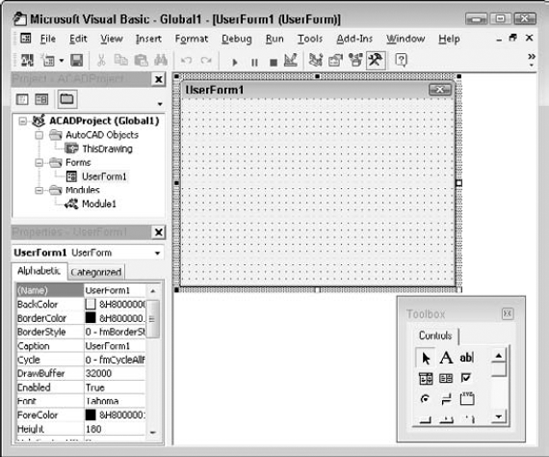
The Toolbox toolbar contains the tools that you need to create a dialog box. These are the familiar controls that you see in the dialog boxes that you use all the time, such as text boxes, list boxes, check boxes, and so on.
Table 37.4 explains the Toolbox toolbar buttons.
Table 37.4. The Toolbox Toolbar Buttons
Button | Description |
|---|---|
Select Objects | Enables the user to select objects |
Label | Creates a label on the dialog box |
TextBox | Enables the user to type in text |
ComboBox | Combines features of text and list boxes |
ListBox | Enables the user to choose from a list |
CheckBox | Creates a box that can be checked or unchecked |
OptionButton | Enables the user to choose one option from several possibilities (also called a radio button) |
ToggleButton | Creates an on/off switch |
Frame | Creates a box around a section of the dialog box |
CommandButton | Creates a button that executes a command, such as OK and Cancel buttons |
TabStrip | Creates tabs along the top of the dialog box |
MultiPage | Creates multiple pages |
ScrollBar | Creates a scroll bar |
SpinButton | Enables the user to specify a number |
Image | Inserts an image |
Tip
For more possibilities, right-click the Toolbox toolbar and choose Additional Controls. From the Additional Controls dialog box, you can choose from many more controls.
After you insert a user form, you should name it. Find the Name property in the Properties window, and change it from UserForm1 (the default name) to any useful name that you want. You might find it useful to use the word frm in the name. For example, for a routine to draw a circle, you could call the user form frmCircle.
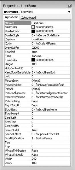
Figure 37.6 shows the property box when you insert a user form. You can easily change the dialog box's properties in the property box.
One property that you'll want to change is the Caption property of the dialog box. The dialog box should have a caption that summarizes its purpose. When you type the new caption in the property box, the caption on the dialog box changes at the same time.
One of the more commonly used controls is the command button. A command button is a button that you click in the dialog box to execute an action. The most familiar command buttons are the OK and Cancel buttons.
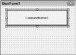
To add a command button, click CommandButton on the Toolbox toolbar. Move your cursor over the dialog box, and drag to create a button. Figure 37.7 shows a dialog box with a new command button. The selection border and handles indicate that the button is a selected object. You can move the button by dragging it. You can resize the button by dragging one of the handles. Add all the command buttons that you need. Don't forget to include at least a Cancel button. Many dialog boxes also have an OK button. If you know in advance all the controls that you'll need, you can add them all at once.
Tip
There's an art to laying out a dialog box so that it's clear and easy to understand. After a while, you'll get the hang of it. Pay more attention to the dialog boxes that you use every day to pick up some design pointers.
Just as the dialog box has properties, each control on the dialog box has properties. When a control such as a command button is selected, you see its properties in the Properties window. You generally would change at least the caption and the name of a command button. It's a good idea to change the names to something meaningful, instead of using the default name. For example, rather than CommandButton1, use a name such as cmdDrawBox or cmdOk.
After you create a command button, you can attach VBA code to it. To attach VBA code to a control, double-click the control. The text editor opens with the Sub and End Sub lines already entered for you. Type the code that you want to attach to the button.
VBA dialog boxes are modal by default, which means that they must be closed before AutoCAD can do anything further. To close a dialog box after your VBA code has run, use Unload Me at the end of a routine.
To run VBA code that is attached to a dialog box, you need to show the dialog box so that you can use it — click a command button, type in text, and so on. The VBA IDE creates private subroutines for each dialog box control. To show the dialog box, start a new module and create code that looks like the code in this example:
Sub DrawArc()
  frmArc.Show
End Sub
FrmArc is the name of the user form in this example. Don't forget to name the user form in the Properties window. Also, remember to name the module, because the module name is what appears in the Macro dialog box when you want to run the routine.
A command button is quite simple. You just click it, and it performs. You can label its function right on the command button. However, most other controls require some more explanation. For example, if you want the user to type in text, you need a text box. However, a text box has no caption. Therefore, you need to add instructions to the user. A dialog box may also need other instructions to clarify the purpose of the controls, which responses are required, and so on.
You add instructions with the Label tool on the Toolbox toolbar. Click Label and drag a rectangle on your dialog box. Then type the label. You can resize or move the label as needed.
The code for some of the dialog box controls can be quite complex. For example, to create a list box that enables the user to choose from an existing list of options, you'd probably create the list of options in advance. For help on creating dialog boxes, choose Help
STEPS: Creating a Dialog Box with a Command Button
Start a new drawing in AutoCAD by using the
acad.dwttemplate.To start a new project, choose Manage tab
Choose Insert
With the user form active (click its title bar to make it active), change the Name property of the user form to
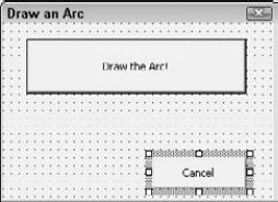
frmArcin the Properties window.Change the Caption property of the user form to Draw an Arc. Watch the caption of the user form change as you type.
Choose CommandButton on the Toolbox toolbar. (It's the last button in the second row. If you don't see the Toolbox toolbar, click in the user form on the right side of your screen.) Move the cursor over the user form and drag to create a wide button across the upper center of the user form.
Change the Caption property of the button to Draw the Arc!. Change the Name property to
cmdDrawArc.Again, choose CommandButton on the Toolbox toolbar. Create a smaller button below the first one near the right side of the user form.
Change the Caption property of the smaller button to Cancel. Change its Name property to
cmdCancel. Your dialog box should look like the one in Figure 37.8.Double-click the larger button. In the text editor, type the following code at the cursor's current location between the
Private SubandEnd Substatements:'declare variables Dim startang As Double Dim endang As Double Dim ctr(0 To 2) As Double Dim rad As Double Dim newarc As Object 'specify arc parameters startang = 0 'angles are in radians. endang = 100 ctr(0) = 5 ctr(1) = 2 ctr(2) = 0 rad = 2 'draw arc Set newarc = ThisDrawing.ModelSpace.AddArc(ctr, rad, startang, endang) 'close dialog box Unload Me
From the left (Object) drop-down list at the top of the text editor, choose cmdCancel to add the code for the second button. In the space below the start of the subroutine
(Private Sub cmdCancel_Click()), type Unload Me.Choose Insert
Sub DrawArc()frmArc.ShowVisual Basic places the
End Substatement for you after the code.In the Properties window, change the module's name to
DrawArc.Click Save on the toolbar and save the file in your
AutoCAD Biblefolder asab37-03.dvb.Return to your drawing. Choose Manage tab
Click the large button. AutoCAD draws the arc.
Getting user input for a circle radius
Here's another example of a routine that draws a circle, although here you get user input for the radius by using the VAL function. The VAL function returns a numerical value from a text string. Here you create a text box that enables users to type in a radius. The VAL function converts the string in the text box to a number and uses it as the circle's radius. Follow these steps:
Open AutoCAD with a new drawing, using the
acad.dwttemplate. Open the VBA IDE.Choose Insert
In the Properties window, change the name of the form to
frmDrawCircle, and change the caption to Draw a Circle Demo.From the Toolbox toolbar, choose Label and drag a small rectangle on the left side of the form, around the middle.
Change the name to lblRadius, and change the caption to Radius.
Choose Textbox on the Toolbox toolbar, and drag a box on the form to the right of the label.
Change the name to
txtRadius.Choose CommandButton on the Toolbox toolbar, and drag a larger box at the top center of the form.
Change the name to
cmdDrawCircle, and change the caption to Draw Circle.Double-click this command button to bring up the text editor in the
cmdDrawCircle_Click ()subroutine.Add the following lines:
Dim dCenter(0 To 2) As Double
Dim dRadius As Double
Dim myCircle as AcadCircle

dCenter(0) = 0#
dCenter(1) = 0#
dCenter(2) = 0#

dRadius = Val(txtRadius)
Set myCircle = ThisDrawing.ModelSpace.AddCircle(dCenter, dRadius)
myCircle.Update
Close the text editor. Save the routine if you want. On the VBA IDE menu, choose Run
Add as many circles as you like. Click the Close box of the dialog box when you're done.
Modifying objects is usually very easy. You need to know the name of the object. If you've created it, you set it equal to a variable, and then you can use that variable.
If you've created a circle named cir1, the following code changes its layer to "fixtures", assuming that "fixtures" exists:
Cir1.layer = "fixtures"
To add a layer, use the Add method of the Layers collection of objects:
Set Newlayer1 = ThisDrawing.Layers.Add("fixtures")You can then set the layer's properties. For example, the following code makes the layer not plottable.
Newlayer1.Plottable = False
The UPDATE method forces the changes to the current view. It updates the change to the screen so that you can see it. For example, you can create a circle with the following code:
Set myCircle = ThisDrawing.ModelSpace.AddCircle(dCenter, cRadius)
This adds the circle to the current drawing's database, but has not yet updated the view. If you do this from a dialog box, the view will not be updated until you exit the dialog box, unless you force an update with the following code:
myCircle.Update
Constants are names that are given to commonly used values. For instance, AutoCAD defines constants for the seven standard colors: acRed, acYellow, acGreen, acCyan, acBlue, acMagenta, and acWhite. In the DrawCircle example, after creating the circle, you could add the following code to change its color to blue:
Dim clrObj As AcadAcCmColor
Set clrObj = myCircle.TrueColor
clrObj.ColorMethod = acColorMethodByACI
clrObj.ColorIndex = acBlue
myCircle.TrueColor = clrObj
Most functions or properties that have a standard set of values will have corresponding constants defined.
Functions are a type of procedure (like subroutines), except that they return a value. Here's an example for those of you who are counting the days until January 1, 2010. (If you're reading this after that date, you can change it to a later date.) Alternatively, it will tell you how many days ago January 1, 2010, occurred (indicated by a negative value).
Function DaysTil2010() As Integer  'notice "As Integer" tells
'the return type of                'the function
    Dim dtToday As Date            'holds today's date
    Dim dt2010 As Date             'holds Jan 1, 2010

    dtToday = Now()                'assign today's date
    dt2010 = CDate("1/1/2010")     'assign Jan 1, 2010
    DaysTil2010 = dt2010 - dtToday 'calculate difference,
'return value assigned             'to function name
End Function                       'same as End Sub
To use this function, you must do something with the return value through an assignment, or use it as a parameter to another procedure. For example:
Public Sub Test2010()
MsgBox "Days until year 2010: " & DaysTil2010()
End Sub
You can then run the Test2010 sub to open a message box that tells you how many days are left until the year 2010.
As with all programming languages, there are techniques to help you find the errors that inevitably crop up. Here is a simple debugging technique to get you started:
Go to the text editor and to the procedure where you suspect the error resides.
Place the cursor on the first executable statement in the procedure, and choose Debug
Begin stepping through each statement by pressing F8 (Step Into).
For simple variables (Integers, Doubles, and Strings), you can place the mouse cursor over the variable, and it will display the current contents. You can also add variables to the Watch window (choose View
When an error is located, choose Run
The next time you run the procedure, your breakpoint is still set. At this point, you can either step through again and verify whether your changes are correct, or press F9 to toggle the breakpoint off and choose Run
Unexpected errors may occur. For example, a file that you attempt to open may not exist, your system may run out of memory and not be able to insert that AutoCAD block into your drawing, or you may unintentionally write a routine that divides by 0. You can, and should, plan for some of these errors; for others, it may not be possible to do so. VBA provides a mechanism for catching errors and handling them gracefully, rather than burping all over your screen or locking up your system.
A simple framework to begin error trapping would be:
Sub MyRoutine()
     'declare variables
     ...
     On Error GoTo ErrorHandler
     'rest of procedure goes here
     Exit Sub     'Tells subroutine to exit ignoring the
                  'ErrorHandler statements

ErrorHandler:
MsgBox "Error " & Err.Number & " " & Err.Description
     Resume Next
End Sub
This simple error trapping will at least alert you to any errors that occur by providing an error number and description. This will give you the opportunity to begin handling specific errors appropriately as required.
The Active X and VBA Developer's Guide has a good discussion on handling errors in the "Developing Applications with VBA" section.
The chapters in this part have reviewed the fundamentals of Visual LISP and VBA, and you've seen the power that these languages provide for automating your work. However, they are not the only options for programming AutoCAD.
ObjectARX applications share the same memory space as AutoCAD, and are many times faster than routines written in AutoLISP or VBA. ObjectARX is based on C++ and enables full object-oriented interfacing with AutoCAD. An object-oriented interface enables the programmer to create an object in memory (such as an arc), modify its attributes, and then modify the AutoCAD database.
You can create custom objects that inherit properties from AutoCAD objects; that is, your object can assume all the properties of a given object that is already in AutoCAD, and you can add to it. For example, you can inherit from a line so that your custom object has everything that the line does, and then you can add width to it if you want. ObjectARX offers a variety of tools that are unavailable to AutoLISP programmers; however, ObjectARX involves much greater development time than AutoLISP. You can use managed wrapper classes within ObjectARX to create .NET applications as well. AutoCAD 2010 requires the Visual C++ 2008 SP1 compiler to compile and link applications for use with AutoCAD. You can obtain ObjectARX at the Autodesk-related Web site www.objectarx.com.
Autodesk is in the processing of moving from the VBA environment to VSTA (Visual Studio Tools for Applications) and the Microsoft .NET framework. Although Autodesk has not set a definite timeline for the replacement of VBA in AutoCAD, it has already taken the first step: not including VBA by default in AutoCAD 2010, as explained at the beginning of this chapter. If you're planning for the future, consider looking at using the AutoCAD .NET API (Application Programming Interface) for new programming projects. AutoCAD 2010 automatically installs the .NET API. The AutoCAD .NET API is more robust than VBA and takes advantage of a modern development environment, Microsoft Visual Studio, as well as newer programming languages, such as VB .NET and C# .NET. For more information on Visual Studio, go to www.microsoft.com/visualstudio.
In this chapter, you learned some basic principles of Visual Basics for Applications as applied to AutoCAD. Specifically, I discussed:
Working with the VBA development environment
Understanding VBA objects, methods, and properties
Principles of writing VBA code
How to get user input
How to create dialog boxes
How to modify objects
Methods of debugging and trapping errors
AutoCAD offers almost unlimited potential for the design and drawing of real-world objects. I hope that this book helps you to understand the world of AutoCAD and makes it easier for you to create the professional drawings that you need to redesign the world and make it a better place. Although I cannot provide technical support for my readers, I would be happy to hear your comments and suggestions at [email protected]. Best wishes and enjoy!