2 | Electricity
Key Concepts in Electricity
This chapter introduces a number of key concepts. In so doing it provides a solid framework for the development of an understanding of the behaviour of electronic components and electrical circuits. In keeping with the stated aims of the book to avoid unnecessary levels of detail, the topics discussed here are presented in a relatively broad fashion, with the goal of facilitating a sufficient degree of understanding to guide the practical electronics to come. The technically inclined reader has at their disposal many more rigorous, academic textbooks to choose from if a deeper treatment is sought (see for example Horowitz and Hill, 2015; Sedra and Smith, 2014). The primary goal in this brief chapter is to provide a description of the importance of, and the relationships between, the following key concepts:
Electric Charge – positively and negatively charged particles are the basis of electricity
Static and Current Electricity – charge can accumulate (static) or it can flow (current)
Current and Circuits – a loop or circuit is generally needed in order for current to flow
Direct and Alternating Current – the flow of current can be one way or bidirectional
Voltage – the push that causes current to flow (voltage up → current up)
Resistance – the opposition to the flow of current (resistance up → current down)
Power – when current flows through a circuit work is done, dissipating power
Electricity and Magnetism – the two mutually dependant aspects of electromagnetism
Conductors and Insulators – materials through which current can and can not flow
Electricity deals with the accumulation and movement of charged particles. Two of the key constituents of all matter are positively charged particles called protons, and negatively charged particles called electrons. Overall the positive charge of the protons and the negative charge of the electrons usually cancel each other out. In certain materials (most notably metals, like copper) some of the electrons are not very tightly bound to any particular location, but rather tend to float about in what can be thought of as a cloud of quite mobile negative charge. There can therefore arise an accumulation of negative charge in one place due to an excess of electrons, and a corresponding accumulation of positive charge in another place due to a scarcity of electrons. There are a number of different ways in which this can happen but, however it comes about, such migrations of charged particles result in the creation of either a static electric charge or a flowing electrical current. Electricity is all about the accumulation and movement of charged particles. When the charged particles are moving the phenomenon is often referred to as current electricity, whereas a localised build-up of charge is called static electricity. All this leads to the three most fundamental and important quantities in basic electrical theory: current, voltage, and resistance.
An analogy is often used when explaining the basics of current electricity flowing in an electrical circuit in which there is a system of pipes and valves with water flowing through them (Figure 2.1). The pipes and valves are the wires and components making up the circuit, and the water is the electricity. When a valve is opened, water flows. How quickly the water flows depends on two things: the water pressure in the pipes and how far the valve is opened. In this analogy the water pressure equates to electrical voltage, and how much the valve has been opened equates to the electrical resistance in the circuit. These two factors combine to control the rate at which water flows in the pipes, one seeking to increase the rate of flow (the voltage or water pressure) while the other tries to limit it (the resistance or the valve). The flow of water itself equates to electrical current.
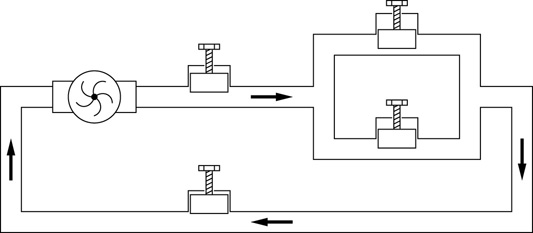
Figure 2.1 Water in pipes as an analogy for an electrical circuit. The speed of the pump corresponds to the voltage of the power supply, the valves represent resistance, and the water flowing is the electrical current.
Add to these three concepts the familiar idea of power, and the four primary quantities used in the analysis of electronics are assembled. Formally power is ‘the rate of doing work’. In other words the amount of work done in a second. Ultimately the kind of work most often of interest here is going to be something like moving the cone of a loudspeaker in and out so as to produce sound. It can therefore be seen why the power of an amplifier is a commonly quoted figure. A one hundred watt guitar amplifier goes louder than a ten watt amp because the one hundred watt amplifier is capable of doing more work per second driving the loudspeaker, and thus a louder sound can be generated.
The terms alternating current and direct current (AC and DC) are also likely to be familiar. These are just two different ways in which current might flow, either bouncing back and forth, constantly changing the direction in which it is flowing (AC), or flowing steadily at a moderately constant rate always in the same direction (DC). Both types of current flow play crucial roles in different aspects of audio electronics.
The close relationship between electricity and magnetism is also explored. Indeed the two are so inextricably linked that they are often talked about in terms of a single compound concept, electromagnetism. The interactions between these two quantities are at the heart of some of the most important audio electrical devices, including the most common types of microphones and loudspeakers. While the details are unimportant in this context, a basic appreciation of their close relationship can help in understanding how audio electronic technology works.
And finally in this chapter on key concepts, conductors and insulators are addressed. How easily electricity flows through various materials is fundamental to controlling and utilising it to do useful things like driving loudspeakers and amplifying signals. Chapter 3 extends this discussion to take in the consideration of some of the most important materials in all of electronics, semiconductors, but for now the focus remains on the more fundamental concepts of simple conductors and insulators.
With a firm grasp on all of this terminology and all of these concepts, the material that follows in subsequent chapters of this book falls more easily into place. A good working knowledge and understanding of the theory of audio electronics can thus be developed, without the need to expand into the more involved theory of the subject. As such, the much more interesting and useful practical aspects of the discipline, which this book makes its primary focus, can be explored and applied to optimum effect.
Electric Charge
As has already been mentioned, charge comes in two flavours, positive and negative, and the movement and accumulation of this charge is at the root of all electricity. Some electrical components can store charge (e.g. capacitors, see Chapter 13) or generate it (e.g. batteries and power supplies), and often such components are referred to as being charged up and discharged. Electric charge is measured in coulombs (C) but for the purposes of this book that particular quantity is not needed.
Electric charge can also be specified in amp-hours, written Ah (1Ah = 3,600C). The place this quantity is most likely to be encountered is written on the side of a rechargeable battery. The capacity of such a battery is often quoted in milliamp-hours (mAh), as in Figure 2.2. (If the ‘milli-’ prefix is unfamiliar see Appendix A for a list of commonly encountered prefix multipliers.) The larger the number, the longer the battery should last on one charge (for batteries of the same rated voltage). Beyond the fact that bigger is generally better, the details of milliamp-hours need not be considered further.

Figure 2.2 Two rechargeable 9V batteries showing their charge holding capacities of 270mAh and 210mAh respectively. A bigger number corresponds to a longer lasting battery.
Static and Current Electricity
Rub a plastic biro or pen through your hair and it can pick up small pieces of paper, or you can deflect the flow of water from a gently running tap. What is observed here is a build up of a little static charge on the plastic. The charge dissipates quickly enough but for a short while the biro becomes an electrically charged rod. Another familiar example of static electricity is the cling experienced when certain synthetic fabrics are rubbed together or pulled over one another. One surface develops a negative charge by accumulating excess electrons while the other becomes positively charged due to a decrease in electron numbers.
By and large static electricity is not of very much interest when talking about audio electronics, although there are a couple of places where it appears. Firstly, remembering what was just said about some fabrics building up a static charge, it is important to be aware that certain electronic components are very sensitive to electrostatic discharge. If such components are touched by someone carrying a static charge they can very easily be damaged. This is most common in certain types of integrated circuits (silicon chips) and transistors. It is important to avoid picking up such components while carrying a static charge, and in general handling them should be kept to a minimum.
When working with these components it is common to wear a special wrist band, as shown in Figure 2.3, connected to earth in order to avoid any chance of static buildup. Static can also be discharged by touching the metal chassis of an earthed piece of equipment. Some dedicated electronics work benches have an earthed strip along their front edge, while others will be covered in an antistatic mat. Both are designed to keep the user and work area free from any build-up of static charge. These are small but important points, which are worth remembering when it comes time to start building circuits or working inside electronic equipment.

Figure 2.3 An antistatic wristband connected to earth can be worn in order to dissipate any build-up of static charge which might otherwise damage sensitive electronic components.
There are also one or two places where static charge plays a key role in the operation of audio electronic components. There is a type of microphone capsule called an electret condenser microphone which depends for its operation on a small permanent static charge held by a piece of electret material within the microphone capsule. Electret material is just a particular type of substance capable of maintaining a static charge over a long period of time. It can be thought of as the electrical equivalent of a permanent magnet. Once an appropriate piece of iron has been magnetised it can stay that way indefinitely. Similarly once a piece of electret material has been charged up it can hold that charge for a very long time. The electret material inside an electret microphone can slowly lose its charge over time, and thus its ability to generate an audio signal, usually over the course of tens of years or more.
While static electricity does come into play in a small way in audio electronics, there is not much about it which needs to be known. For the most part what is of real interest is not static but rather current electricity, electricity flowing around a circuit, and in the process doing useful and interesting things. This is described next.
Current and Circuits
The first thing to remember about electricity in the context of electronic circuits is that in order for an electric current to flow, a closed circuit is needed. That is to say a loop such that the current can flow around and end up back where it started, tracing an unbroken path through wires and components. The other thing needed for current to flow is a source, something capable of actually generating the current flow. For a first, simple (and somewhat unlikely) electrical circuit imagine a battery (that’s the source), and a piece of copper wire running from one terminal to the other. This is a valid electric circuit, although also not very useful and generally not a good idea. It would be referred to as a ‘short circuit’, and it allows as much current as the source can provide to flow through the wire. The battery is likely to get very hot and could be damaged or destroyed. Although there are exceptions, in the context of practical circuit building, short circuits such as this are generally to be avoided.
What is needed is to add a non-zero load to the circuit to limit the amount of current flowing (and hopefully do something useful in the process). In electrical terms anything attached between the terminals of a battery constitutes a load, but let’s keep it simple and just add a little torch bulb (Figure 2.4). Now current flows out of the positive terminal of the battery, through a piece of wire, through the bulb, and then through a second piece of wire and back to the negative terminal of the battery. Assuming the battery is charged and the bulb is suitable and the filament intact, light will be produced. No matter how big and complex a circuit gets this basic principle holds. Current will flow out of the positive terminal of the source along the various paths in the circuit and back into the negative side of the source.
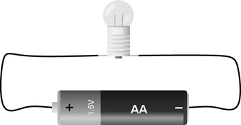
Figure 2.4 In order for any electronic device (no matter how simple or how complex) to work, a loop or circuit must exist providing an unbroken path from one side of the power source back to the other.
It is often useful to be able to say exactly how much current is flowing. Electrical current is measured in amperes or amps (A), and is an indication of how much electricity is flowing. Different circuits will allow different amounts of current to flow depending on the characteristics of the circuit and of the source. One ampere is quite a large current for the kind of battery powered circuits involved here, but it is a fairly modest current for many familiar electrical devices especially mains powered equipment: kettles, toasters, and of course larger audio power amplifiers.
Some mains power plugs (mainly the type used in the UK and Ireland, see Chapter 4, p. 41), contain a fuse. These fuses are typically rated at between about three and thirteen amps. A fuse is really just a tiny piece of wire designed to burn out if more than the rated current is allowed to flow through it. This is a crude but effective safety feature used to limit the chances of large, dangerous currents being allowed to flow unchecked due to a fault in wiring or equipment.
The smaller amounts of current which are usually involved in battery powered audio circuits can be measured in milliamps (mA). A milliamp is one thousandth of an amp. It can be a good idea to keep an eye on how much current a circuit draws. For battery powered devices this gives an idea of how long the circuit will be able to run before the batteries will need changing or recharging. And if the required current in a circuit starts rising too high it may be necessary to look at how much heat is being generated in the circuit, and if any components need to be replaced with ones that can better handle the higher levels of current flowing. These considerations are addressed as individual components and general questions of circuit design are explored later.
Electric Current and Electrons
Electric current is taken to flow from positive to negative within a circuit, while physical electrons actually propagate in the other direction. This positive to negative direction is called conventional current flow. It does not really matter which direction is used so long as it is applied consistently, and so some authors have taken to equating the direction of current flow with the direction of electron movement. This is never done in this book but it is worth being aware that this reversed convention for the direction of current flow might occasionally be encountered elsewhere. So long as it is applied consistently it does not represent a problem.
Sticking to the conventional positive to negative direction for current flow might be seen to have the added merit of highlighting that an electric current may be associated with the movement of charged particles (negative or positive) other than electrons.
The separation between electrons and electric current is further re-enforced by another important distinction. Electrical signals propagate around a circuit at a significant fraction of the speed of light (in other words very fast indeed) whereas the electrons (or other charged particles) that generate the electric current that constitutes such a signal typically move much, much more slowly.
Electric current is the propagation of an electric field, not the movement of the charged particles themselves. It is only the propagation of the field which is of interest here, i.e. the electrical signal not the moving particles that are responsible for generating it, but again reference may occasionally be encountered to this much slower movement, usually referred to as the drift velocity of the electrons, typically on the order of millimetres per second in electrical wires, and these two speeds of propagation are sometimes confused.
Direct and Alternating Current
A direct current means that a (moderately) constant amount of current (number of amps) flows always in the same direction. For an alternating current the direction in which the current flows keeps reversing, first one way and then the other, so the actual electrons never really go anywhere they just keep jiggling back and forth. The graphs in Figure 2.5 illustrate the difference between a DC and an AC signal.
Here the DC plot is a good way to think of what happens at the terminals of a battery and the AC signal, represented here as a simple sine wave, would be a very good visualisation of the signal present on the live conductor of a mains power socket. However an AC signal can also be a much more complex affair and this is of particular interest here, as this is how an acoustic sound signal is represented electrically, as for example in the short audio sample displayed in Figure 2.6, where the graph shows a very complex signal variation over time. This same graph could represent either the air pressure changes of an acoustic sound signal or the voltage variations of an electrical sound signal.

Figure 2.5 Direct current (DC) and alternating current (AC) electrical signals. With DC the level and polarity stays constant over time whereas with AC it continually swings between positive and negative.

Figure 2.6 The example audio signal illustrated here is much more complex than the simple sine wave AC signal shown above in Figure 2.5 but both are AC signals.
As has been said, conventional current always flows in a circuit from points at a more positive voltage to points at a more negative voltage within the circuit (recall it flowed out the positive battery terminal and around the circuit, always heading back towards the negative terminal). In the case of this simple circuit the only voltage source present is the battery. Batteries only provide constant, steady voltages (the voltage will drop slowly as the battery discharges, but as far as any analysis is concerned a battery is a constant voltage source). So in the circuit in Figure 2.4 above only direct current (DC) is present. Compare this with a mains powered desk lamp, where a mains AC signal is used to run the light bulb. This circuit is effectively identical to the one shown in the figure, except for the nature of the source driving it. A standard incandescent light bulb can run equally well from a DC or an AC source, as all it needs to do in order to give off light is to get hot and glow. Most circuits are rather more particular as to how they are powered, and audio circuits usually require a DC power supply.
Finally on the subject of DC and AC signals, another way in which audio signals are often encountered is as a combination of an AC component and a DC component. How this is usually described is as an AC signal with a DC offset or bias, see Figure 2.7. This idea of applying a constant offset or bias to an audio signal can be quite useful, as is seen when it comes time to examine various audio circuits later in this book.

Figure 2.7 An AC signal with a DC offset or bias. The dashed sine wave oscillates equally either side of the zero line whereas with a DC bias added the mid point of the resulting sine wave (solid line) is located at a non-zero position.
Voltage
Voltage, measured in volts (V), is the electrical push that attempts to cause current to flow. So for example the 9V battery in Figure 2.2 pushes harder than the AA or AAA batteries shown in Figure 2.8. Voltages are measured between two points in a circuit; when referring to voltages they are described as being between point A and point B, or across component X.
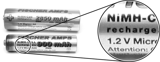
Figure 2.8 Fresh AA and AAA batteries typically generate a steady voltage or EMF of approximately 1.5V. This voltage will of course slowly fall off as the battery is used and the charge it holds is dissipated. It is also worth noting that, while historically 1.5V is the established output for such batteries, newer battery types, especially rechargeables, can vary from this level, with 1.2V often being quoted (see inset).
It is worth noting that a number of alternative terms can be encountered all meaning much the same thing, although sometimes applied in different contexts. They are all talking about voltages, but it is worth being aware of them so that they do not cause confusion if encountered. The voltage generated by a battery or other source will sometimes be referred to as an electromotive force, or EMF for short. So it might be said that the AA or AAA batteries in Figure 2.8 each generates an EMF of 1.2V.
When talking about a voltage across components or parts of a circuit other than a source, it is often called a potential difference or PD. So the bulb in Figure 2.4 has a PD of 1.5 volts across it since it is connected directly to the two terminals of the battery, while the battery itself might be quoted as having an EMF of 1.5 volts. The related terms ‘potential’ or ‘electrical potential’ are often used when talking about the voltage at a point in a circuit relative to a predefined reference point designated as being zero volts. For a simple battery powered circuit this zero reference point is often taken to be the negative terminal of the battery but this is not essential. All voltages are relative and it is just necessary to know where they are being measured relative to. These ideas are important and are encountered again when it comes to examining the operation of circuits throughout the rest of this book.
There is one more term which is sometimes used to refer to voltage, and that is tension, used especially where talking about very high voltages. So the big power lines that carry electricity across the countryside are often called high tension lines. This does not mean that they are stretched very tight (indeed they usually hang quite slack). It refers to the extremely high voltages used to transmit power over long distances. The acronym EHT meaning extra high tension is often encountered written on signs around power substations or other places where high voltages exist.
Resistance
Resistance is measured in ohms (Ω) and can be thought of as the opposition to the flow of electricity in a circuit. Resistance is a property of the components themselves and exists independent of the presence of any voltage or current. In other words a component’s resistance is there all the time regardless of whether or not the component is in a circuit, and regardless of whether or not electricity has been applied to the circuit.
Another name which is often used almost interchangeably with resistance is impedance. Resistance and impedance are both measured in ohms and in general impedance is actually made up of two components called resistance and reactance (which is never much talked about on its own here). One useful way of thinking about the relationship between resistance and impedance is to remember that resistance is more to do with DC circuits and impedance is more to do with the more complex interactions present when considering AC circuits.
The places where impedance is most commonly encountered when working in audio in general are loudspeakers and amplifiers (remember audio signals are AC so usually relate to impedance rather than resistance). Figure 2.9 shows the back of a loudspeaker where the impedance is marked as 8Ω. Four, eight, and sixteen are common impedances for loudspeakers. Power amplifiers are typically designed to operate with a specific range of loudspeaker impedances.

Figure 2.9 Eight ohm (8Ω), half watt (0.5W), two and a half inch diameter loudspeakers. Speakers are most commonly found in impedances of 4Ω, 8Ω, and 16Ω.
Power
Electrical power is a measure of how much work per second is being done by the components or a circuit. Power is measured in watts (W), or for many of the smaller, low power audio circuits of interest here, in milliwatts (mW). In audio circuits (as in many other circuits) inefficient use of incoming power leading to the generation of unwanted heat can be a major problem, and various strategies are employed in order to cool circuits to prevent them from overheating and failing. Fans and heat sinks are designed to remove excess heat from a circuit. High power circuits such as amplifiers need careful attention paid to the questions of ventilation and cooling if they are to operate without problems over long periods of time. A heat sink is a piece of material with good thermal conduction and a large surface area so that it can radiate the heat it gathers into the surrounding air (or occasionally water or some other fluid). Heat sinks are attached firmly to any components that get especially hot, like for instance the power transistors in an amplifier. The job of a fan is to keep cool air moving over the surface of the heat sink so as to maximise the transfer of heat into the air and away from the hot circuitry, thus dissipating the maximum amount of power.
Amplifiers are very often described in terms of their power output capabilities (a one hundred watt amplifier etc.), and the second important characteristic for a loudspeaker along with the impedance mentioned before is its power handling capability, i.e. how much power an amplifier can drive into it before it starts distorting badly, and running the risk of being damaged.
Electricity and Magnetism
The finer details of the nature of and the relationship between electricity and magnetism are areas of ongoing advanced practical and theoretical research, and these questions are deeply entangled with the areas of quantum mechanics, relativity, and high energy physics. Fortunately these details need not be considered here. It is however useful to develop a passing acquaintance with some of the more basic but nonetheless important concepts involved. The first thing worth remembering is that the effects of an electrical signal flowing in a circuit are not limited to within the components and the wires that make up the circuit. An electromagnetic field extends out from the current carriers and can have both wanted and unwanted effects in the general vicinity.
Electric and magnetic fields can to a large extent be viewed as just two aspects of the greater single electromagnetic field. The idea of a permanent magnet should be familiar, with a field surrounding it which can have an effect on certain metals and other magnets close by, without any physical contact. One magnet can be made to push another across a tabletop without the two ever touching. A compass can be relied upon to find north because the compass needle is a magnet and its field interacts with the earth’s magnetic field to line up showing north–south. But remember also that a compass can easily be fooled by stronger magnetic fields produced by electrical devices and other magnets in the vicinity. The freely rotating compass needle lines up with the strongest magnetic field it finds. In fact a compass is occasionally used in this fashion when working with electric guitar pickups as it provides an easy method of determining the orientation of the magnets in the pickup, which can be useful information when wiring multiple pickups into a guitar (see Learning by Doing 20.4).
Electromagnetic induction is the process used to generate the majority of electricity around the world. All that is needed in order to generate an electric current is to move an electrical conductor in close proximity to a magnet. This is what is found in the generators in an electric power plant, and it is also what happens in probably the commonest type of microphone, the ubiquitous dynamic mic. Fundamentally all that a dynamic microphone consists of is a very fine coil of wire attached to a diaphragm and suspended in a magnetic field. Sound travels through the air, hits the diaphragm and makes it vibrate back and forth in time with the sound. This moves the coil which is sitting in the magnetic field, and a tiny electrical signal is generated by electromagnetic induction. The generated signal voltage varies up and down exactly as the diaphragm is moved back and forth, and so an electrical signal is created that is an excellent representation of the original acoustic sound arriving at the diaphragm.
In fact electromagnetic induction is a two way process. The previous description showed that moving a conductor in a magnetic field produces an electric current, but it also works in the other direction. Placing a conductor in a magnetic field and sending an electric current through it produces a force on the conductor. This is the principle of the electric motor, as illustrated in Figure 2.10. Motors and generators have identical configurations at their core, and indeed if an electric motor for example from a CD player is spun by hand a voltage can be measured at its terminals – the motor is acting as a generator. So it can be seen that electromagnetic induction is widely used in both its directions of operation: motion used to generate a signal as in a dynamic microphone, and a signal used to generate motion as in a moving coil loudspeaker.

Figure 2.10 An electric motor combines electricity and magnetism to produce movement. A generator uses the same mechanism in reverse to produce electricity from magnetism and movement.
Thus as the dynamic microphone mentioned earlier takes movement and produces a signal, so a moving coil loudspeaker takes an electric current and produces movement. And just as a motor can be a generator and vice versa, so too loudspeakers can be (and occasionally are) used as microphones to pick up sound, and indeed microphones can be made to generate sound like a tiny loudspeaker (although not very loud and probably to the detriment of the microphone). The pickups on an electric guitar are another example of electromagnetic induction in action, and more examples can be found elsewhere in audio technology. All in all the phenomenon plays a crucial role in the technology of this area.
Electromagnetic interference illustrates that just as electromagnetism can be used to achieve many useful tasks, it can also present serious difficulties in audio electronics. Since electromagnetic fields abound in electronics they can often go places and do things which are not wanted. Electromagnetic interference (EMI) is the cause of many a noisy circuit and many a corrupted signal. Whether it be a steady hum, a sudden click, or an unwanted radio broadcast breaking through, noise and interference can often find their way onto an audio signal through the mechanisms of electromagnetic interference.
An understanding of where such unwanted signals come from and how they make their way into circuits is important if they are to be kept out, leading to circuits which produce clean and clear audio signals. In various places throughout this book techniques for grounding, shielding, and cancelling unwanted noise signals in circuits are encountered.
Conductors and Insulators
The next chapter in this book is all about semiconductors so it would seem appropriate to finish off this chapter with a section on conductors and insulators, the two extremes to which semiconductors can be thought of as forming a part of the centre ground. Resistance has already been introduced as the quantity that measures how easily electricity flows in a material. Good conductors have very low resistance while good insulators have extremely high resistance. There are materials all along the scale from very low to very high resistance. Table 2.1 lists a few examples of good, intermediate, and poor conductors, with their resistivities listed beside them. Resistivity, measured in ohm-metres (Ω · m), gives an indication of the characteristic resistive properties for a material. Note that a long piece of wire has a greater resistance between its ends than a shorter piece of the same wire, and so simple resistance in ohms (Ω) is not a suitable quantity to provide a general characterisation for the resistive properties of a particular material. The highlighted Box 2.1 on p. 25 provides an explanation of why ohm-metres (Ω · m) emerge as the appropriate units for resistivity.
Table 2.1 Some typical resistivities for a range of materials
Material |
Resistivity (Ω · m) |
Category |
Silver |
0.000,000,016 |
|
Copper |
0.000,000,017 |
|
Conductor |
Gold 0.000,000,024 |
|
Aluminium |
0.000,000,028 |
|
Silicon (doped)a |
0.003,2 |
|
Salt Water |
0.20 |
|
Germanium (pure) |
0.46 |
Intermediate |
Fresh Water |
200.0 |
|
Silicon (pure) |
640.0 |
|
Glass (silica) |
10,000,000,000,000.0 |
|
Rubber |
10,000,000,000,000.0 |
Insulator |
Wood (dry) |
1,000,000,000,000,000.0 |
|
Air |
23,000,000,000,000,000.0 |
a. The resistivity of doped semiconductor material is highly dependant on the type and concentration of the dopant used. See Chapter 3 for more on semiconductor doping.
It can be seen from the table why copper is a good choice for making electrical wires. It has an extremely low resistivity meaning that it will allow current to flow without offering any great resistance and so it does not waste energy getting hot and dissipating power. Rubber on the other hand has a very high resistivity and as such forms a suitable basis for the insulation that wires might be wrapped in, preventing unwanted contacts with other conductive objects in the vicinity. Uninsulated conductors are occasionally (but not often) encountered. They are of course not really uninsulated. They are just insulated by air, which is in fact a very good insulator. The only problem with it is that solid, possibly conducting, objects can pass straight through it and touch the conductor in question. However, overhead power lines for instance are often left uninsulated as nothing conducting should normally come in contact with them. The heating elements in a toaster are sometimes also formed from uninsulated conductors, so be careful when sticking a knife in to dig out your toast.
As discussed in the next chapter, a few of those materials in the intermediate section of Table 2.1 turn out to have some extremely interesting properties. This means that they are ideal for making a very useful type of substance called a semiconductor. Silicon is the one most people have heard about, in terms of silicon chips, the things computers are made of. In fact before silicon semiconductors came along, germanium was the element of choice. Germanium based semiconductors are much less common now but are still used in some audio circuits for some of their particular characteristics.
Open Circuits and Short Circuits
If two things or two points in a circuit have a path between them along which electricity can flow then they are said to be connected. If there is no electrical path between them they are disconnected or isolated. A very low resistance connection (close to zero ohms) can be described as a short circuit. Two completely disconnected points can be described as an open circuit. In practical electronics, the terms short circuit and open circuit are usually (though not always) used to describe unwanted or fault conditions. When a fuse is overloaded and burns out it is described as having gone open circuit. Conversely an unwanted electrical connection, perhaps caused by stray solder or a loose wire touching where it shouldn’t is called a short circuit.
In building an electronic project two of the most common problems encountered are unwanted short circuits and open circuits.
A short circuit (aka short or dead short) can arise if too much solder is used when connecting components. The excess solder can flow onto a nearby connection point creating a solder bridge and resulting in a short circuit between two points in the circuit which should not be connected. Short circuits are also commonly encountered if sufficient care is not taken when connecting stranded wire into a circuit. A single loose strand of copper, finer than a human hair, is all it takes to cause a problem.
An open circuit can be introduced if solder joints are not well made. Insufficient heat or moving the joint while it cools can prevent the solder from bonding properly resulting in what is called a dry solder joint. This is a joint which may look good but which provides a very poor electrical connection. It can result in a permanently or intermittently open circuit and a noisy or non-operational device.
The terms are occasionally also used to describe wanted or intended situations, like the state of a switch or a connection point in a circuit. For example a system might be reset by shorting together two normally disconnected points in the circuit. It is common practice when tidying up unused portions of some types of circuit to short unused inputs to ground and to leave unused outputs open circuit. These practicalities are examined in more detail in the sections on circuit building in Part II.
References
K. Brindley. Starting Electronics. Newnes, 4th edition, 2011.
A. Hackmann. Electronics: Concepts, Labs, and Projects. Hal Leonard, 2014.
P. Horowitz and W. Hill. The Art of Electronics. Cambridge University Press, 3rd edition, 2015.
R. Jaeger and T. Blalock. Microelectronic Circuit Design. McGraw-Hill, 4th edition, 2011.
A. Sedra and K. Smith. Microelectronic Circuits. Oxford University Press, 7th edition, 2014.